EP0105127A1 - Rotary compressor - Google Patents
Rotary compressor Download PDFInfo
- Publication number
- EP0105127A1 EP0105127A1 EP19830107665 EP83107665A EP0105127A1 EP 0105127 A1 EP0105127 A1 EP 0105127A1 EP 19830107665 EP19830107665 EP 19830107665 EP 83107665 A EP83107665 A EP 83107665A EP 0105127 A1 EP0105127 A1 EP 0105127A1
- Authority
- EP
- European Patent Office
- Prior art keywords
- sealed container
- oil
- lubricating oil
- rotary compressor
- gas
- Prior art date
- Legal status (The legal status is an assumption and is not a legal conclusion. Google has not performed a legal analysis and makes no representation as to the accuracy of the status listed.)
- Granted
Links
Images


Classifications
-
- F—MECHANICAL ENGINEERING; LIGHTING; HEATING; WEAPONS; BLASTING
- F04—POSITIVE - DISPLACEMENT MACHINES FOR LIQUIDS; PUMPS FOR LIQUIDS OR ELASTIC FLUIDS
- F04C—ROTARY-PISTON, OR OSCILLATING-PISTON, POSITIVE-DISPLACEMENT MACHINES FOR LIQUIDS; ROTARY-PISTON, OR OSCILLATING-PISTON, POSITIVE-DISPLACEMENT PUMPS
- F04C29/00—Component parts, details or accessories of pumps or pumping installations, not provided for in groups F04C18/00 - F04C28/00
- F04C29/02—Lubrication; Lubricant separation
Definitions
- This invention relates to a rotary compressor, and, more particularly, it is concerned with the rotary compressor of a type, in which lubricating oil is cooled by a heat-exchanger for improving the performance and reliability in its operation.
- the present invention aims at improving those disadvantages inherent in the conventional compressor so as to provide such compressing machine which can be assembled readily and has excellent operational performance and reliability.
- a rotary compressor which comprises: a compression chamber defined by enclosing both ends of a cylinder with a main bearing and an end bearing; compression elements including a piston which is eccentrically rotated by a crank shaft within the compression chamber, and dividing the compression chamber into a high pressure chamber and a low pressure chamber; and a sealed container to be a plenum space, in which the compression elements are housed and lubricating oil is sumped at the inner bottom section of the sealed container to effect lubrication of sliding parts of the compression elements, wherein the lubricating oil is returned into the sealed container after it has been cooled through a heat-exchanger provided outside the sealed container.
- a horizontal type rotary compressor which comprises: a compression chamber defined by enclosing both ends of a cylinder with a main bearing and an end bearing; compression elements including a piston which is eccentrically rotated by a crank shaft within the compression chamber, and dividing the compression chamber into a high pressure chamber and a low pressure chamber; and a sealed container to form a plenum space, in which the compression elements are housed and lubricating oil is sumped at the inner bottom section of the sealed container to perform lubrication of sliding parts of the compression elements, wherein there are further provided a communicating port formed in said cylinder so as to introduce discharged coolant gas from the compression chamber; a large diameter section of said communicating port, which is expanded in the lubricating oil; an ejecting pipe, one end of which is inserted into said communicating port and opened in said large diameter section thereof; and an oil inducing path which intersects orthogonally with said large diameter section and passes through said cylinder, the lubric
- Figure 1 is a cross-sectional view of the rotary compressor according to the first embodiment of the present invention
- Figure 2 is a perspective view of the main part of the rotary compressor according to the first embodiment of the present invention.
- a reference numeral 1 designates a hermetically sealed container
- numerals 2 and 3 refer respectively to an electric motor and compression elements housed in the hermetically sealed container
- numeral 7 refers to a crank shaft to be driven by the electric motor 2, and others.
- the above-mentioned compression elements 3 comprise a piston 8 fitted on the crank shaft, a vane (not shown in the drawing) with its one end being in contact with the piston and performing reciprocating motion, main and end bearings 5, 6 to support the above-mentioned crank shaft 7, and a cylinder 4 provided in between the two bearings.
- the interior of this cylinder is divided by the above-mentioned vane, as is well known, into a high pressure chamber and a low pressure chamber for the coolant so that inlet and outlet of the coolant can be repeated by the eccentric rotation of the crank shaft 7.
- the coolant gas compressed in the above-described manner passes through a discharge port 12 and a discharge valve 13 formed in and provided on the main bearing 5, and discharged into a silencing chamber 14 provided at the outside of the main bearing to the discharge side of the coolant.
- a numeral 15 refers to a gas passage hole through the cylinder 4 between the main bearing 5 and the end bearing 6.
- a reference numeral 16 denotes a gas discharge tube with its fixed end being inserted into this gas passage hole, the other end of the gas discharge tube being a gas discharging end portion 16a which is opened in an oil guiding tube 17, one end of which is also opened in the lubricating oil 19 sumped in the hermetically sealed container 1.
- This oil guiding tube (or oil feeding tube) 17 is opened:, at the other end thereof, in the sealed container through a heat-exchanger 18 provided at the outside thereof.
- the discharged gas from the compression chamber is led into a lubricating oil feeding end 17a of the oil feeding tube 17 through the discharge end portion 16a of the gas discharge tube 16.
- the lubricating oil 19 standing at the bottom part of the sealed container 1 is drawn into the oil feeding tube 17 through a gap A formed in an overlapped portion between the gas discharge tube and the oil feeding tube, is forwarded to the heat-exchanger 18 provided outside the sealed container together with an ejected gas from the gas discharge tube, and is fed back into the sealed container 1 again through a feeding end portion 17b.
- the lubricating oil at the inner bottom part of the sealed container circulates in the oil feeding tube, while discharging heat, whereby it keeps discharging heat transmitted from the electric motor, the compression elements, and so on.
- the temperature of the compressor as a whole inclusive of the compression elements, the lubricating oil, and so on is lowered with the consequence that not only the performance of the compressor improves due to inhibition against preheating of the intake gas, improvement in sealing against leakage of the lubricating oil, etc., but also reliability of the device such as improvement in the lubricating property, etc. becomes effectively augmented.
- the temperature in the electric motor element 2, the compression elements 3, the lubricating oil 19, and so forth can be lowered, whereby the temperature of the compressor as a whole can be decreased.
- the performance of the compressor improves due to inhibition against preheating of the intake gas, improvement in sealing against leakage of the lubricating oil, improvement in the operating efficiency of the motor, and so forth, and the reliability of the compressor also improves due to inhibition against deterioration of the insulating material for the electric motor.
- the coolant gas which has been drawn in from the intake tube 9 and compressed passes through the discharge port 12 and the discharge valve 13 formed in and provided on the main bearing 5, and discharged into the silencing chamber 14 at the discharge side, after which it further passes through the gas passage hole 15 through the main and end bearings 5, 6 and the cylinder 4 therebetween, and then is led into the gas discharge tube 16, the fixed end of which is inserted into the gas.passage hole.
- the compressed coolant gas from the compression chamber is discharged into the oil feeding tube 30 from the end part of the gas discharge tube 30.
- the lubricating oil standing at the bottom part of the sealed container 1 is sucked into the discharge tube 16 through a gap 33 formed in the overlapped section between the discharge tube 16 and the oil feeding tube 30, which passes through the heat-exchanger 31 provided outside the sealed container 1, and is again sent into the sealed container.
- the third embodiment of the present invention causes the lubricating oil to circulate, while discharging heat through the heat-exchanger.
- the temperature in the compression elements, the electric motor element, further the lubricating oil, and so forth becomes lowered, hence the temperature of the compressor as a whole can be decreased, and also the performance of the compressor can be improved due to inhibition against preheating of the intake gas, improvement in sealing against leakage of the lubricating oil, improvement in working efficiency of the electric motor, and others.
- reliability of the compressor can be remarkably improved as the result of improvement in the lubricating performance, inhibtion against deterioration in the insulating material for the electric motor elements, and so forth.
- the internal space of the compressor can be reduced, which contributes to realizing reduction in size of the compressor.
- a reference numeral 41 designates the sealed container; numerals 42, 43 respectively refer to the electric motor section and the compression elements housed in the sealed container; and a numeral 47 refers to the crank shaft to be driven by the electric motor section 42, etc., which is disposed in the horizontal direction.
- the compression elements 43 comprises the piston 48 fitted onto the crank shaft, the vane (not shown in the drawing) with its one end being in contact with the piston, and which performs its reciprocating motion, the main and end bearings 45, 46 to support the crank shaft 47, and the cylinder 44 positioned between the two bearings.
- the interior of this cylinder is divided, as is well known, by the above-mentioned vane into the high pressure chamber and the low pressure chamber so that the inlet and outlet of the coolant may be repeated by the eccentric rotation of the crank shaft 47.
- the coolant gas which has been compressed in the above-mentioned manner passes through the discharging valve 53 provided on the main bearing 45, and is discharged into the silencing chamber 54 at its discharge side provided outside the main bearing 45.
- a reference numeral 55 denotes the gas passage hole through the main and end bearings 45, 46 and the cylinder 44 disposed between them.
- a reference numeral 56 designates a communciating port which is formed through in such a manner that one end of it is open to the lower surface of the cylinder 43, and the other end thereof is open at a position away from the open end 55a of the gas passage hole which is open to the above-mentioned end bearing 46.
- This communicating port has a large diameter section 57 in the vicinity of the lower end of the cylinder where its diameter is expanded.
- a reference numeral 58 indicates an ejecting pipe with its one end being inserted into this communicating port and with its other end being opened in the large diameter section 57 contiguous to the sealed container 41. This ejecting pipe forms a space gap between its outer periphery and the large diameter section.
- a numeral 59 refers to an oil inducing path which passes through the cylinder 43 interior so as to be opposed to the side surface of the ejecting pipe 58. This oil inducing path is opened in the lubricating oil 60 standing at the inner bottom part of the sealed container 41.
- a reference numeral 61 designates an oil feeding pipe, one end of which is connected with a bar ring 62 opened to the lower surface wall of the sealed container 41 in opposition to the above-mentioned large diameter section 57, and the other end of which is connected with the oil feeding path 63 provided in the cylinder 43 passing through the upper surface wall of the sealed container 41.
- a numeral 64 refers to the heat-exchanger which is connected intermediate of the oil feeding pipe, and provided outside the sealed container.
- a numeral 65 refers to an oil sump vessel in a substantially cup-shape having an oil sump section between the end surfaces of the end bearing 46.
- the oil sump vessel has a flange portion 65a to fit on the outer surface of the end bearing 46, and forms a gas flow path 66 by bulging out the above-mentioned flange portion 65a in a manner as to connecting the open end of the gas passage hole 55a in the end bearing 46 and the open end 56a of the communicating port. Moreover, these oil sump vessel 65 and the oil feeding pipe 63 are connected by the oil feeding pipe 61.
- a reference numeral 67 denotes an oil feeding port passing concentrically through the above-mentioned crank shaft 47. By this oil feeding port, oil is fed to the sliding parts through a branch port 67a.
- the discharged gas from the compression chamber passes through the silencing chamber 54 at the discharge side thereof and the gas passage hole 55, and is led into the ejecting pipe 58 in the communicating port through the gas flow path formed in the above-mentioned oil sump vessel 65.
- the lubricating oil at the inner bottom part of the sealed container circulates, while discharging heat, whereby it continues to discharge heat to be transmitted from the electric motor section, the compression elements, and others.
- the temperature of the compression elements, the lubricating oil, etc. hence the temperature of the compressor as a whole, is lowered.
- the performance of the compressor improves due to inhibition against preheating of the intake gas, improvements in the sealing property of the lubricating oil, etc., but also the effect to reliability of the operation of the device such as improvement in the lubricating performance, etc. is also great.
- a reference numeral 70 is designated by the gas passage hole which passes through the main bearing 45 at a position close to the discharge valve 53 and through the cylinder 44 in a shape of a letter "L" , and is opened toward the lower surface of the cylinder in its radial direction.
- This gas passage hole is joined with the communicating port 71 of a large diameter.
- the external heat-exchanger 64 for cooling the lubricating oil is connected with the large diameter part of the communicating port 71 at the outer peripheral part of the cylinder through the pipe 75.
- the other end of the heat-exchanger 64 is communicatively connected with the substantially cup-shaped oil sump vessel 77 which has been press-fitted on the outer periphery of the flanged part of the end bearing 46 through the oil guiding pipe 76 passing through the sealed container 41, whereby the lubricating oil in this oil sump vessel is distributed to each of the sliding parts through the oil feeding ports (not shown in the drawing) opened in the above-mentioned crank shaft 47. Further, the outer peripheral part of this oil sump vessel is press-fitted in and fixed on the flange portion of the end bearing 46.
- the discharged coolant gas from the compression chamber passes through the silencing chamber 54 at the discharge side and the gas passage hole 70, and is ejected from the above-mentioned ejecting pipe 72 within the entrance portion of the heat-exchanger, i.e., within the large diameter portion. of the communicating port 71. Then, it is sent into the heat-exchanger 64 provided outside the sealed container together with the lubricating oil 60 drawn thereinto through the space gap 74 at the overlapped portion between the inner diameter portion of the communicating port 71 and the outer diameter portion of the ejecting pipe 72. After the heat-exchange, the gas is sent back into the sealed container again.
- the lubricating oil is sent back into the above-mentioned substantially cup-shaped oil sump vessel 77 through the oil guiding pipe 76 in the sealed container. After this, the lubricating oil is distributed to each of the sliding parts, while the coolant gas is discharged into the sealed container from the end surface of the crank shaft 47 at the side of the electric motor.
- the lubricating oil at the inner bottom part of the sealed container circulates, while discharging heat, whereby it continues to discharge heat to be transmitted from the electric motor section, the compression elements, and others.
- the temperature of the compressor as a whole including the compression elements, the lubricating oil, and so on is lowered, not only the performance of the compressor improves due to inhibition against preheating of the intake gas, improvement in the sealing property against leakage of the lubricating oil, and so forth, but also the effect to reliability of the compressor such as improvement in the lubricating performance, etc. is also great.
- the compressor can be installed either in the horizontal direction or in the vertical direction, whereby the best mode of its use with good space saving installation can be expected.
- a reference numeral 80 designates the discharge valve which is provided at the side of the end bearing (cylinder head) 6, and the discharge silencer 81 is mounted at the side of the cylinder head 6, i.e. , at the lower surface side of the cylinder 4.
- a numeral 82 refers to an intromitting port for the oil feeding pipe, which is formed in the lower side surface of the hermetically sealed container 1 where the lubricating oil 19 gathers.
- the manner of insertion is such that, after the compression elements 3 and the electric motor element 2 have been inserted into the hermetically sealed container 1, a connecting tube 83 which has previously been set in the oil guiding pipe 17 is inserted into the bar ring hole 84 formed in the discharge silencer 81 from the oil guiding pipe intro- nitting port 82.
- the diameter of the bar ring hole 84 and that of the connecting tube 83 to be inserted into this bar ring hole is substantially same, so that they are tightly fitted and sealed by insertion into the other.
- the pipe 17 is hermetically fusion-bonded by soldering to the oil guiding pipe intromitting port.
- the sixth embodiment of the present invention is so constructed that the oil guiding pipe 17 is directly inserted into the discharge silencer 81, the pressure loss at the connecting hole becomes eliminated in comparison with the case of the Figure 2 embodiment.
- the coolant gas is taken out from the side surface of the hermetically sealed container, a difference in height between the oil feeding port and the oil returning port can be reduced.
Abstract
Description
- This invention relates to a rotary compressor, and, more particularly, it is concerned with the rotary compressor of a type, in which lubricating oil is cooled by a heat-exchanger for improving the performance and reliability in its operation.
- In the conventional compressing machine, particularly, in a compressor of a large capacity, there is an increase in quantity of heat to be generated from various compressing elements in it, whereas quantity of heat to be dispersed does not increase correspondingly, with the consequence that the temperature of the compressing machine as a whole goes up. On account of this, there take place not only preheating of intake gas, deterioration in sealing against leakage of lubricating oil, lowering in operating efficiency of electric motor, etc. to thereby cause decrease in the operational performance of the compressor, but also lowering of the film sustaining force of the lubricating oil, deterioration in the insulating material for the electric motor, etc., all of which resulted in decrease in operational reliability of the machine.
- Therefore, with a view to increasing the discharging quantity of heat from the compressor, there has been employed various means such as an oil cooler, and so forth. In the conventional oil cooler, however, since a part of its coolant circuit is drawn into a tightly sealed container, tubing and assembly in the sealed container interior and at the side of a unit using such compressor becomes complicated to result in increase in the manufacturing cost.
- The present invention aims at improving those disadvantages inherent in the conventional compressor so as to provide such compressing machine which can be assembled readily and has excellent operational performance and reliability.
- It is another object of the present invention to provide a compressor with its performance being improved by cooling the lubricating oil in the compressor through a heat-exchange installed outside the sealed container, and, after cooling, returning the same into the sealed container.
- It is other object of the present invention to provide an improved compressor of a construction, in which the lubricating oil is forwarded to a heat-exchanger in utilization of pressure excerted at the time of discharging the coolant gas.
- According to the present invention, in one aspect of it, there is provided a rotary compressor which comprises: a compression chamber defined by enclosing both ends of a cylinder with a main bearing and an end bearing; compression elements including a piston which is eccentrically rotated by a crank shaft within the compression chamber, and dividing the compression chamber into a high pressure chamber and a low pressure chamber; and a sealed container to be a plenum space, in which the compression elements are housed and lubricating oil is sumped at the inner bottom section of the sealed container to effect lubrication of sliding parts of the compression elements, wherein the lubricating oil is returned into the sealed container after it has been cooled through a heat-exchanger provided outside the sealed container.
- According to the present invention, in another aspect of it, there is provided a horizontal type rotary compressor, which comprises: a compression chamber defined by enclosing both ends of a cylinder with a main bearing and an end bearing; compression elements including a piston which is eccentrically rotated by a crank shaft within the compression chamber, and dividing the compression chamber into a high pressure chamber and a low pressure chamber; and a sealed container to form a plenum space, in which the compression elements are housed and lubricating oil is sumped at the inner bottom section of the sealed container to perform lubrication of sliding parts of the compression elements, wherein there are further provided a communicating port formed in said cylinder so as to introduce discharged coolant gas from the compression chamber; a large diameter section of said communicating port, which is expanded in the lubricating oil; an ejecting pipe, one end of which is inserted into said communicating port and opened in said large diameter section thereof; and an oil inducing path which intersects orthogonally with said large diameter section and passes through said cylinder, the lubricating oil being let out of said oil inducing path, being caused to pass through a heat-exchanger provided outside said sealed container together with the discharged gas, and being returned into the sealed container.
- The foregoing objects, other objects as well as the specific construction and functions of the rotary compressor according to the present invention will become more apparent and understandable from the following detailed description of several preferred embodiments thereof, when read in conjunction with the accompanying drawing.
- In the accompanying drawing:
- Figure 1 is a cross-sectional view of the first embodiment of the rotary compressor according to the present invention;
- Figure 2 is a perspective view showing the main part of the rotary compressor of Figure 1, which is partly cut out;
- Figure 3 is a cross-sectional view of the second embodiment of the rotary compressor according to the present invention, in which a device for cooling the lubricating oil is provided ;
- Figure 4 is a perspective view showing the main part of the rotary compressor of Figure 3, which is partly cut out;
- Figure 5 is a cross-sectional view of the third embodiment of the rotary compressor according to the present invention, in which a lubricating oil cooling circuit is provided;
- Figure 6 is a perspective view, partly cut out, of the main part of the rotary compressor according to the present invention;
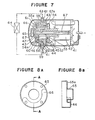
- Figure 7 is a cross-sectional view of the fourth embodiment of the rotary compressor according to the present invention;
- Figure 8A is a plan view of an oil sump in the rotary compressor shown in Figure 7.
- Figure 8B is a cross-sectional view of the oil sump shown in Figure 8A, taken along the line A-A in Figure 8A;
- Figure 9 is a side elevational view, partly cut away, of the fifth embodiment of the rotary compressor according to the present invention;
- Figure 10A is a plan view of the oil sump in the rotary compressor shown in Figure 9; and
- Figure 10B is a cross-sectional view of the oil sump shown in Figure 10A, taken along the line B-B in Figure 10A.
- Figure 11 is a side elevational view, in longitudinal cross-section, of a hermetically sealed type rotary compressor according to the present invention in its sixth embodiment.
- In the following, the present invention will be described in specific details in reference to Figures 1 and 2 showing the first preferred embodiment of thereof. -
- 'Figure 1 is a cross-sectional view of the rotary compressor according to the first embodiment of the present invention, and Figure 2 is a perspective view of the main part of the rotary compressor according to the first embodiment of the present invention. In the drawing, a reference numeral 1 designates a hermetically sealed container;
numerals numeral 7 refers to a crank shaft to be driven by theelectric motor 2, and others. The above-mentionedcompression elements 3 comprise apiston 8 fitted on the crank shaft, a vane (not shown in the drawing) with its one end being in contact with the piston and performing reciprocating motion, main andend bearings crank shaft 7, and acylinder 4 provided in between the two bearings. The interior of this cylinder is divided by the above-mentioned vane, as is well known, into a high pressure chamber and a low pressure chamber for the coolant so that inlet and outlet of the coolant can be repeated by the eccentric rotation of thecrank shaft 7. - The coolant gas compressed in the above-described manner passes through a
discharge port 12 and adischarge valve 13 formed in and provided on themain bearing 5, and discharged into asilencing chamber 14 provided at the outside of the main bearing to the discharge side of the coolant. Anumeral 15 refers to a gas passage hole through thecylinder 4 between the main bearing 5 and the end bearing 6. Areference numeral 16 denotes a gas discharge tube with its fixed end being inserted into this gas passage hole, the other end of the gas discharge tube being a gas discharging end portion 16a which is opened in anoil guiding tube 17, one end of which is also opened in the lubricatingoil 19 sumped in the hermetically sealed container 1. This oil guiding tube (or oil feeding tube) 17 is opened:, at the other end thereof, in the sealed container through a heat-exchanger 18 provided at the outside thereof. As the consequence of this, the discharged gas from the compression chamber is led into a lubricatingoil feeding end 17a of theoil feeding tube 17 through the discharge end portion 16a of thegas discharge tube 16. In this case, the lubricatingoil 19 standing at the bottom part of the sealed container 1 is drawn into theoil feeding tube 17 through a gap A formed in an overlapped portion between the gas discharge tube and the oil feeding tube, is forwarded to the heat-exchanger 18 provided outside the sealed container together with an ejected gas from the gas discharge tube, and is fed back into the sealed container 1 again through afeeding end portion 17b. - Since the first embodiment of the rotary compressor according to the present invention is constructed as mentioned in the foregoing, the lubricating oil at the inner bottom part of the sealed container circulates in the oil feeding tube, while discharging heat, whereby it keeps discharging heat transmitted from the electric motor, the compression elements, and so on. In this manner, the temperature of the compressor as a whole inclusive of the compression elements, the lubricating oil, and so on is lowered with the consequence that not only the performance of the compressor improves due to inhibition against preheating of the intake gas, improvement in sealing against leakage of the lubricating oil, etc., but also reliability of the device such as improvement in the lubricating property, etc. becomes effectively augmented.
- In the following, the second embodiment of the present invention will be explained in detail in reference to Figures 3 and 4. It should be noted that, in the drawing, those parts which are same with or similar to those in the Figure 1 embodiment will be designated by the same reference numerals. In this embodiment of the invention, the rotary compressor performs its operation in the manner to be described in the following.
- The coolant gas as drawn into from the
intake tube 9 is compressed by thepiston 8 which rotates eccentrically in thecylinder 4. The thus compressed coolant gas passes through theoutlet valve 13 provided on themain bearing 5 to be discharged into thesilencing chamber 14, further passes through thegas passage hole 15 through the main andend bearings cylinder 4 therebetween, and is led into aconnecting tube 20, one end of which is joined with the gas passage hole. This connecting tube for leading the discharged gas is expanded its diameter in the lubricatingoil 19 standing at the inner bottom part of the sealed container 1.Small holes 24 for sucking the lubricating oil are formed in the vicinity of astepped part 23 between thesmall diameter part 21 and thelarge diameter part 22 of the connectingtube 20. The other end of this connectingtube 20 is led to the heat-exchanger 18 installed outside the sealed container 1 by way of the bottom part thereof, and is again connected with another connectingtube 25 which is again opened in the sealed container 1 after the heat-exchange with the outside air. - Accordingly, the compressed coolant gas which has been led into the connecting
tube 20 through thegas passage hole 15 is further led to the heat-exchanger 18 provided outside the sealed container 1 together with the lubricatingoil 19 which has been drawn into the connecting tube through thesmall holes 24 which are opened at the stepped part of the connecting tube and for sucking the lubricating oil, and then is sent into the sealed container 1 again through the connectingtube 25 for the heat-exchanger 18. That is to say, owing to the lubricatingoil 19 repeating its circulation together with the compressed coolant gas, while discharging heat therefrom, the heat generated from theelectric motor 2 and thecompression elements 3 is constantly kept discharged outside. In this manner, the temperature in theelectric motor element 2, thecompression elements 3, the lubricatingoil 19, and so forth can be lowered, whereby the temperature of the compressor as a whole can be decreased. As the result of this, the performance of the compressor improves due to inhibition against preheating of the intake gas, improvement in sealing against leakage of the lubricating oil, improvement in the operating efficiency of the motor, and so forth, and the reliability of the compressor also improves due to inhibition against deterioration of the insulating material for the electric motor. - In the following, the third embodiment of the present invention will be explained in reference to Figures 5 and 6. It should be noted that, in the drawing, those parts which are same as or similar to those as shown in Figure 1 are designated by the same reference numerals. In this embodiment, the rotary compressor performs its operation in the manner to be described as follows.
- The coolant gas which has been drawn in from the
intake tube 9 and compressed passes through thedischarge port 12 and thedischarge valve 13 formed in and provided on themain bearing 5, and discharged into thesilencing chamber 14 at the discharge side, after which it further passes through thegas passage hole 15 through the main andend bearings cylinder 4 therebetween, and then is led into thegas discharge tube 16, the fixed end of which is inserted into the gas.passage hole. Areference numeral 30 designates an oil feeding tube, one end of which is opened to the collecting section for the lubricatingoil 19 in the above-mentioned sealed container 1; a numeral 31 refers to the heat-exchanger for cooling the lubricating oil, which is provided outside the sealed container; and anumeral 32 denotes the connecting tube which is opened to the side wall of the sealed container 1 so as to be communicating with the upper space of thecylinder 4. This connecting tube is connected in series with the heat-exchanger 31 and theoil feeding tube 30, the other end of the above-mentionedgas discharging tube 16 being opened into thisoil feeding tube 30. - Accordingly, the compressed coolant gas from the compression chamber is discharged into the
oil feeding tube 30 from the end part of thegas discharge tube 30. The lubricating oil standing at the bottom part of the sealed container 1 is sucked into thedischarge tube 16 through agap 33 formed in the overlapped section between thedischarge tube 16 and theoil feeding tube 30, which passes through the heat-exchanger 31 provided outside the sealed container 1, and is again sent into the sealed container. - As mentioned in the foregoing, the third embodiment of the present invention causes the lubricating oil to circulate, while discharging heat through the heat-exchanger. By discharging heat to be transmitted from the compression elements and the electric motor, and so forth, the temperature in the compression elements, the electric motor element, further the lubricating oil, and so forth becomes lowered, hence the temperature of the compressor as a whole can be decreased, and also the performance of the compressor can be improved due to inhibition against preheating of the intake gas, improvement in sealing against leakage of the lubricating oil, improvement in working efficiency of the electric motor, and others. Furthermore, reliability of the compressor can be remarkably improved as the result of improvement in the lubricating performance, inhibtion against deterioration in the insulating material for the electric motor elements, and so forth.
- Moreover, by providing a member, at which the gas discharge tube and the oil feeding tube are joined, at a position outside the sealed container, the internal space of the compressor can be reduced, which contributes to realizing reduction in size of the compressor.
- In the following, the fourth embodiment of the present invention will be explained in reference to Figure 7 illustrating a horizontal type rotary compressor. In Figure 7, a
reference numeral 41 designates the sealed container;numerals numeral 47 refers to the crank shaft to be driven by theelectric motor section 42, etc., which is disposed in the horizontal direction. Thecompression elements 43 comprises thepiston 48 fitted onto the crank shaft, the vane (not shown in the drawing) with its one end being in contact with the piston, and which performs its reciprocating motion, the main andend bearings crank shaft 47, and thecylinder 44 positioned between the two bearings. The interior of this cylinder is divided, as is well known, by the above-mentioned vane into the high pressure chamber and the low pressure chamber so that the inlet and outlet of the coolant may be repeated by the eccentric rotation of thecrank shaft 47. - The coolant gas which has been compressed in the above-mentioned manner passes through the discharging
valve 53 provided on themain bearing 45, and is discharged into the silencingchamber 54 at its discharge side provided outside themain bearing 45. Areference numeral 55 denotes the gas passage hole through the main and endbearings cylinder 44 disposed between them. - A
reference numeral 56 designates a communciating port which is formed through in such a manner that one end of it is open to the lower surface of thecylinder 43, and the other end thereof is open at a position away from theopen end 55a of the gas passage hole which is open to the above-mentionedend bearing 46. This communicating port has a large diameter section 57 in the vicinity of the lower end of the cylinder where its diameter is expanded. A reference numeral 58 indicates an ejecting pipe with its one end being inserted into this communicating port and with its other end being opened in the large diameter section 57 contiguous to the sealedcontainer 41. This ejecting pipe forms a space gap between its outer periphery and the large diameter section. A numeral 59 refers to an oil inducing path which passes through thecylinder 43 interior so as to be opposed to the side surface of the ejecting pipe 58. This oil inducing path is opened in the lubricatingoil 60 standing at the inner bottom part of the sealedcontainer 41. - A
reference numeral 61 designates an oil feeding pipe, one end of which is connected with a bar ring 62 opened to the lower surface wall of the sealedcontainer 41 in opposition to the above-mentioned large diameter section 57, and the other end of which is connected with theoil feeding path 63 provided in thecylinder 43 passing through the upper surface wall of the sealedcontainer 41. A numeral 64 refers to the heat-exchanger which is connected intermediate of the oil feeding pipe, and provided outside the sealed container. A numeral 65 refers to an oil sump vessel in a substantially cup-shape having an oil sump section between the end surfaces of theend bearing 46. The oil sump vessel has aflange portion 65a to fit on the outer surface of the end bearing 46, and forms agas flow path 66 by bulging out the above-mentionedflange portion 65a in a manner as to connecting the open end of thegas passage hole 55a in the end bearing 46 and theopen end 56a of the communicating port. Moreover, theseoil sump vessel 65 and theoil feeding pipe 63 are connected by theoil feeding pipe 61. By the way, areference numeral 67 denotes an oil feeding port passing concentrically through the above-mentionedcrank shaft 47. By this oil feeding port, oil is fed to the sliding parts through abranch port 67a. - On account of such construction, the discharged gas from the compression chamber passes through the silencing
chamber 54 at the discharge side thereof and thegas passage hole 55, and is led into the ejecting pipe 58 in the communicating port through the gas flow path formed in the above-mentionedoil sump vessel 65. Then, the gas ejected at the large diameter section 57 is forwarded to the heat-exchanger 64 outside the sealed container together with oil drawn into the large diameter section through the space gap formed between the ejecting pipe and the large diameter section to be cooled, after which it is returned to the sealedcontainer 41, wherein the oil is sent to theoil sump veseel 65 through theoil guiding path 63 and theoil feeding pipe 61, after which it is distributed to every sliding parts, while the coolant, gas is discharged into the sealedcontainer 41 from the end surface of thecrank shaft 47 at the side of the electric motor. - As described in the foregoing, according to this fourth embodiment of the present invention, the lubricating oil at the inner bottom part of the sealed container circulates, while discharging heat, whereby it continues to discharge heat to be transmitted from the electric motor section, the compression elements, and others. In this way, the temperature of the compression elements, the lubricating oil, etc., hence the temperature of the compressor as a whole, is lowered. On account of this, not only the performance of the compressor improves due to inhibition against preheating of the intake gas, improvements in the sealing property of the lubricating oil, etc., but also the effect to reliability of the operation of the device such as improvement in the lubricating performance, etc. is also great.
- In the following, the fifth embodiment of the rotary compressor according to the present invention is explained in reference to Figure 9. It should be noted that, in the drawing, those parts which are identical with or similar to those in the Figure 7 embodiment are designated by the same reference numerals. In Figure 9, a
reference numeral 70 is designated by the gas passage hole which passes through themain bearing 45 at a position close to thedischarge valve 53 and through thecylinder 44 in a shape of a letter "L" , and is opened toward the lower surface of the cylinder in its radial direction. This gas passage hole is joined with the communicatingport 71 of a large diameter. - A
reference numeral 72 denotes the ejecting pipe with its one end being press-fitted into the small diameter part of the communicating port. The other end of this ejectingpipe 72 is opened in the large diameter part of the communicatingport 71 in the neighborhood of the entrance into the heat-exchanger installed outside the sealed container. A numeral 73 refers to the oil inducing path opened in the cylinder immersed in the lubricatingoil 60 at the bottom part of the sealed container so as to intersect orthogonally with the large diameter part of the communicatingport 71. This oil inducing path is communicatively connected with thespace gap 74 between the inner diameter part of the communicatingport 71 and the outer diameter part of the ejectingpipe 72. Incidentally, the external heat-exchanger 64 for cooling the lubricating oil is connected with the large diameter part of the communicatingport 71 at the outer peripheral part of the cylinder through thepipe 75. The other end of the heat-exchanger 64 is communicatively connected with the substantially cup-shapedoil sump vessel 77 which has been press-fitted on the outer periphery of the flanged part of the end bearing 46 through theoil guiding pipe 76 passing through the sealedcontainer 41, whereby the lubricating oil in this oil sump vessel is distributed to each of the sliding parts through the oil feeding ports (not shown in the drawing) opened in the above-mentionedcrank shaft 47. Further, the outer peripheral part of this oil sump vessel is press-fitted in and fixed on the flange portion of theend bearing 46. - Accordingly, the discharged coolant gas from the compression chamber passes through the silencing
chamber 54 at the discharge side and thegas passage hole 70, and is ejected from the above-mentionedejecting pipe 72 within the entrance portion of the heat-exchanger, i.e., within the large diameter portion. of the communicatingport 71. Then, it is sent into the heat-exchanger 64 provided outside the sealed container together with the lubricatingoil 60 drawn thereinto through thespace gap 74 at the overlapped portion between the inner diameter portion of the communicatingport 71 and the outer diameter portion of the ejectingpipe 72. After the heat-exchange, the gas is sent back into the sealed container again. On the other hand, the lubricating oil is sent back into the above-mentioned substantially cup-shapedoil sump vessel 77 through theoil guiding pipe 76 in the sealed container. After this, the lubricating oil is distributed to each of the sliding parts, while the coolant gas is discharged into the sealed container from the end surface of thecrank shaft 47 at the side of the electric motor. - Since the fifth embodiment of the rotaty compressor according to the present invention is constructed as described in the foregoing, the lubricating oil at the inner bottom part of the sealed container circulates, while discharging heat, whereby it continues to discharge heat to be transmitted from the electric motor section, the compression elements, and others. In this way, since the temperature of the compressor as a whole including the compression elements, the lubricating oil, and so on is lowered, not only the performance of the compressor improves due to inhibition against preheating of the intake gas, improvement in the sealing property against leakage of the lubricating oil, and so forth, but also the effect to reliability of the compressor such as improvement in the lubricating performance, etc. is also great. Further, with such construction as in the present invention, the compressor can be installed either in the horizontal direction or in the vertical direction, whereby the best mode of its use with good space saving installation can be expected.
- In the following, the sixth embodiment of the rotary compressor according to the present invention will be explained in reference to Figure 11. It should be noted that, in the drawing, those parts which are identical with or similar to those in the construction of Figure 1 will be designated by the same reference numerals, and the explanations thereof will be dispensed with.
- This embodiment of the present invention is concerned with improvement in the construction shown in Figure 2, wherein the cooland gas discharged at the side of the
main bearing 5 passes through themain bearing 5, thecylinder 4, and the end bearing 6 to reach the dischargingtube 83 to decrease the pressure loss to occur among these parts and to increase the operational efficiency of the compressor which has once been lowered by the pressure loss, and, at the same time, since theoil guiding pipe 17 is positioned at the bottom part of the sealed container 1, a difference in height between theoil guiding pipe 17 and theoil feeding end 17b is large with the consequence that the lubricating oil gathers in theoil guiding pipe 17 to thereby prevent the discharged coolant gas from flowing back into the lubricatingoil 19 from theoil guiding pipe 17. - In Figure 11, a
reference numeral 80 designates the discharge valve which is provided at the side of the end bearing (cylinder head) 6, and thedischarge silencer 81 is mounted at the side of thecylinder head 6, i.e. , at the lower surface side of thecylinder 4. A numeral 82 refers to an intromitting port for the oil feeding pipe, which is formed in the lower side surface of the hermetically sealed container 1 where the lubricatingoil 19 gathers. The manner of insertion is such that, after thecompression elements 3 and theelectric motor element 2 have been inserted into the hermetically sealed container 1, a connectingtube 83 which has previously been set in theoil guiding pipe 17 is inserted into thebar ring hole 84 formed in thedischarge silencer 81 from the oil guiding pipe intro-nitting port 82. The diameter of thebar ring hole 84 and that of the connectingtube 83 to be inserted into this bar ring hole is substantially same, so that they are tightly fitted and sealed by insertion into the other. - And, after insertion of the
oil guiding pipe 17, thepipe 17 is hermetically fusion-bonded by soldering to the oil guiding pipe intromitting port. - As described in the foregoing, since the sixth embodiment of the present invention is so constructed that the
oil guiding pipe 17 is directly inserted into thedischarge silencer 81, the pressure loss at the connecting hole becomes eliminated in comparison with the case of the Figure 2 embodiment. In addition, since the coolant gas is taken out from the side surface of the hermetically sealed container, a difference in height between the oil feeding port and the oil returning port can be reduced.
Claims (10)
Applications Claiming Priority (12)
| Application Number | Priority Date | Filing Date | Title |
|---|---|---|---|
| JP15031982A JPS5939991A (en) | 1982-08-30 | 1982-08-30 | Rotary compressor |
| JP150319/82 | 1982-08-30 | ||
| JP148474/82 | 1982-09-30 | ||
| JP14847382U JPS5952197U (en) | 1982-09-30 | 1982-09-30 | rotary compressor |
| JP14847482U JPS5952198U (en) | 1982-09-30 | 1982-09-30 | Horizontal rotary compressor |
| JP148473/82 | 1982-09-30 | ||
| JP15769782U JPS5962289U (en) | 1982-10-19 | 1982-10-19 | Rotary compressor lubricating oil cooling system |
| JP157697/82 | 1982-10-19 | ||
| JP17527982U JPS5979575U (en) | 1982-11-19 | 1982-11-19 | Closed type rotary compressor |
| JP17527882U JPS5979574U (en) | 1982-11-19 | 1982-11-19 | rotary compressor |
| JP175278/82 | 1982-11-19 | ||
| JP175279/82 | 1982-11-19 |
Publications (2)
| Publication Number | Publication Date |
|---|---|
| EP0105127A1 true EP0105127A1 (en) | 1984-04-11 |
| EP0105127B1 EP0105127B1 (en) | 1987-06-16 |
Family
ID=27553044
Family Applications (1)
| Application Number | Title | Priority Date | Filing Date |
|---|---|---|---|
| EP19830107665 Expired EP0105127B1 (en) | 1982-08-30 | 1983-08-04 | Rotary compressor |
Country Status (5)
| Country | Link |
|---|---|
| EP (1) | EP0105127B1 (en) |
| AU (1) | AU548548B2 (en) |
| DE (1) | DE3372117D1 (en) |
| DK (1) | DK156672C (en) |
| MX (2) | MX153949A (en) |
Cited By (4)
| Publication number | Priority date | Publication date | Assignee | Title |
|---|---|---|---|---|
| EP0173013A2 (en) * | 1984-06-25 | 1986-03-05 | Mitsubishi Denki Kabushiki Kaisha | Rotary compressor |
| EP0195560A2 (en) * | 1985-03-14 | 1986-09-24 | Kabushiki Kaisha Toshiba | Rotary compressor |
| AU585439B2 (en) * | 1987-04-14 | 1989-06-15 | Mitsubishi Denki Kabushiki Kaisha | Rotary compressor |
| CN114017334A (en) * | 2021-11-08 | 2022-02-08 | 广东美芝制冷设备有限公司 | Rotary compressor and refrigeration equipment with same |
Citations (4)
| Publication number | Priority date | Publication date | Assignee | Title |
|---|---|---|---|---|
| GB382227A (en) * | 1931-05-15 | 1932-10-20 | Bosch Robert | Improvements in or relating to refrigerating machines |
| US1967035A (en) * | 1933-05-08 | 1934-07-17 | Lipman Patents Corp | Motor compressor unit |
| US2178425A (en) * | 1937-02-18 | 1939-10-31 | Gen Electric | Refrigerating machine |
| US2623365A (en) * | 1947-07-14 | 1952-12-30 | Leonard J Daniel | Refrigerator pump |
-
1983
- 1983-08-04 EP EP19830107665 patent/EP0105127B1/en not_active Expired
- 1983-08-04 AU AU17607/83A patent/AU548548B2/en not_active Ceased
- 1983-08-04 DE DE8383107665T patent/DE3372117D1/en not_active Expired
- 1983-08-25 DK DK389183A patent/DK156672C/en not_active IP Right Cessation
- 1983-08-29 MX MX19853483A patent/MX153949A/en unknown
- 1983-08-29 MX MX56783A patent/MX158883A/en unknown
Patent Citations (4)
| Publication number | Priority date | Publication date | Assignee | Title |
|---|---|---|---|---|
| GB382227A (en) * | 1931-05-15 | 1932-10-20 | Bosch Robert | Improvements in or relating to refrigerating machines |
| US1967035A (en) * | 1933-05-08 | 1934-07-17 | Lipman Patents Corp | Motor compressor unit |
| US2178425A (en) * | 1937-02-18 | 1939-10-31 | Gen Electric | Refrigerating machine |
| US2623365A (en) * | 1947-07-14 | 1952-12-30 | Leonard J Daniel | Refrigerator pump |
Cited By (7)
| Publication number | Priority date | Publication date | Assignee | Title |
|---|---|---|---|---|
| EP0173013A2 (en) * | 1984-06-25 | 1986-03-05 | Mitsubishi Denki Kabushiki Kaisha | Rotary compressor |
| EP0173013A3 (en) * | 1984-06-25 | 1987-01-14 | Mitsubishi Denki Kabushiki Kaisha | Rotary compressor |
| EP0195560A2 (en) * | 1985-03-14 | 1986-09-24 | Kabushiki Kaisha Toshiba | Rotary compressor |
| EP0195560A3 (en) * | 1985-03-14 | 1988-06-01 | Kabushiki Kaisha Toshiba | Rotary compressor |
| AU585439B2 (en) * | 1987-04-14 | 1989-06-15 | Mitsubishi Denki Kabushiki Kaisha | Rotary compressor |
| CN114017334A (en) * | 2021-11-08 | 2022-02-08 | 广东美芝制冷设备有限公司 | Rotary compressor and refrigeration equipment with same |
| CN114017334B (en) * | 2021-11-08 | 2023-09-05 | 广东美芝制冷设备有限公司 | Rotary compressor and refrigeration equipment with same |
Also Published As
| Publication number | Publication date |
|---|---|
| DK389183D0 (en) | 1983-08-25 |
| EP0105127B1 (en) | 1987-06-16 |
| MX153949A (en) | 1987-02-24 |
| DK389183A (en) | 1984-03-01 |
| MX158883A (en) | 1989-03-29 |
| AU1760783A (en) | 1984-03-08 |
| AU548548B2 (en) | 1985-12-19 |
| DK156672B (en) | 1989-09-18 |
| DE3372117D1 (en) | 1987-07-23 |
| DK156672C (en) | 1990-02-12 |
Similar Documents
| Publication | Publication Date | Title |
|---|---|---|
| US4569645A (en) | Rotary compressor with heat exchanger | |
| EP0173013B1 (en) | Rotary compressor | |
| US7473079B2 (en) | Electric compressor with inverter | |
| US4385875A (en) | Rotary compressor with fluid diode check value for lubricating pump | |
| US7074024B2 (en) | Scroll-type fluid machine having a path to pass and cool the fluid | |
| KR970003262B1 (en) | Motor compressor | |
| CA1246507A (en) | Oil dispersing device | |
| EP0569119B1 (en) | Rotary compressor | |
| EP0588381B1 (en) | Hermetic compressor | |
| KR19980081422A (en) | Scroll Machine with Emission Duct | |
| EP0105127A1 (en) | Rotary compressor | |
| US4968223A (en) | Gas and oil cooling system for a hermetic compressor | |
| US4502854A (en) | Vane compressor having rearwardly located suction connector and discharge connector | |
| JP4167456B2 (en) | Electric compressor | |
| US4400142A (en) | Motor-compressor unit | |
| CN210484057U (en) | Horizontal compressor | |
| EP0322531A2 (en) | Rotary compressor gas routing for muffler system | |
| JPS6213786A (en) | Closed type compressor | |
| CN110848135B (en) | Horizontal compressor and heat exchange working equipment | |
| CN217029317U (en) | Rotor compressor, compressor assembly and air conditioner outdoor unit | |
| CN215949826U (en) | Compressor shell and compressor | |
| JP2563591B2 (en) | Scroll compressor | |
| JPH0626473A (en) | Scroll compressor | |
| JPS6350695A (en) | Rotary compressor | |
| JPS6336072A (en) | Electric compressor |
Legal Events
| Date | Code | Title | Description |
|---|---|---|---|
| PUAI | Public reference made under article 153(3) epc to a published international application that has entered the european phase |
Free format text: ORIGINAL CODE: 0009012 |
|
| AK | Designated contracting states |
Designated state(s): DE FR GB IT SE |
|
| 17P | Request for examination filed |
Effective date: 19840409 |
|
| GRAA | (expected) grant |
Free format text: ORIGINAL CODE: 0009210 |
|
| AK | Designated contracting states |
Kind code of ref document: B1 Designated state(s): DE FR GB IT SE |
|
| ITF | It: translation for a ep patent filed |
Owner name: ING. A. GIAMBROCONO & C. S.R.L. |
|
| REF | Corresponds to: |
Ref document number: 3372117 Country of ref document: DE Date of ref document: 19870723 |
|
| ET | Fr: translation filed | ||
| PLBE | No opposition filed within time limit |
Free format text: ORIGINAL CODE: 0009261 |
|
| STAA | Information on the status of an ep patent application or granted ep patent |
Free format text: STATUS: NO OPPOSITION FILED WITHIN TIME LIMIT |
|
| 26N | No opposition filed | ||
| PGFP | Annual fee paid to national office [announced via postgrant information from national office to epo] |
Ref country code: GB Payment date: 19890731 Year of fee payment: 7 |
|
| PGFP | Annual fee paid to national office [announced via postgrant information from national office to epo] |
Ref country code: FR Payment date: 19890808 Year of fee payment: 7 |
|
| PGFP | Annual fee paid to national office [announced via postgrant information from national office to epo] |
Ref country code: SE Payment date: 19890810 Year of fee payment: 7 |
|
| ITTA | It: last paid annual fee | ||
| PGFP | Annual fee paid to national office [announced via postgrant information from national office to epo] |
Ref country code: DE Payment date: 19890929 Year of fee payment: 7 |
|
| PG25 | Lapsed in a contracting state [announced via postgrant information from national office to epo] |
Ref country code: GB Effective date: 19900804 |
|
| PG25 | Lapsed in a contracting state [announced via postgrant information from national office to epo] |
Ref country code: SE Effective date: 19900805 |
|
| GBPC | Gb: european patent ceased through non-payment of renewal fee | ||
| PG25 | Lapsed in a contracting state [announced via postgrant information from national office to epo] |
Ref country code: FR Effective date: 19910430 |
|
| PG25 | Lapsed in a contracting state [announced via postgrant information from national office to epo] |
Ref country code: DE Effective date: 19910501 |
|
| REG | Reference to a national code |
Ref country code: FR Ref legal event code: ST |
|
| EUG | Se: european patent has lapsed |
Ref document number: 83107665.8 Effective date: 19910410 |