EP0104985B1 - Enrouleur statique de fil métallique - Google Patents
Enrouleur statique de fil métallique Download PDFInfo
- Publication number
- EP0104985B1 EP0104985B1 EP83401770A EP83401770A EP0104985B1 EP 0104985 B1 EP0104985 B1 EP 0104985B1 EP 83401770 A EP83401770 A EP 83401770A EP 83401770 A EP83401770 A EP 83401770A EP 0104985 B1 EP0104985 B1 EP 0104985B1
- Authority
- EP
- European Patent Office
- Prior art keywords
- rotation
- drum
- hollow shaft
- cam
- driven
- Prior art date
- Legal status (The legal status is an assumption and is not a legal conclusion. Google has not performed a legal analysis and makes no representation as to the accuracy of the status listed.)
- Expired
Links
Images
Classifications
-
- B—PERFORMING OPERATIONS; TRANSPORTING
- B21—MECHANICAL METAL-WORKING WITHOUT ESSENTIALLY REMOVING MATERIAL; PUNCHING METAL
- B21C—MANUFACTURE OF METAL SHEETS, WIRE, RODS, TUBES, PROFILES OR LIKE SEMI-MANUFACTURED PRODUCTS OTHERWISE THAN BY ROLLING; AUXILIARY OPERATIONS USED IN CONNECTION WITH METAL-WORKING WITHOUT ESSENTIALLY REMOVING MATERIAL
- B21C47/00—Winding-up, coiling or winding-off metal wire, metal band or other flexible metal material characterised by features relevant to metal processing only
- B21C47/02—Winding-up or coiling
- B21C47/10—Winding-up or coiling by means of a moving guide
- B21C47/14—Winding-up or coiling by means of a moving guide by means of a rotating guide, e.g. laying the material around a stationary reel or drum
-
- B—PERFORMING OPERATIONS; TRANSPORTING
- B65—CONVEYING; PACKING; STORING; HANDLING THIN OR FILAMENTARY MATERIAL
- B65H—HANDLING THIN OR FILAMENTARY MATERIAL, e.g. SHEETS, WEBS, CABLES
- B65H54/00—Winding, coiling, or depositing filamentary material
- B65H54/76—Depositing materials in cans or receptacles
- B65H54/80—Apparatus in which the depositing device or the receptacle is rotated
- B65H54/82—Apparatus in which the depositing device or the receptacle is rotated and in which coils are formed before deposition
Definitions
- the present invention relates to a static wire winder.
- a static winder is known, marketed by the Belgian company N.V. MACHINES FRANS-SENS under the references BS 800 or BS 1000, in which the wire is wound on a drum immobilized in rotation.
- the wire first passes through a hollow shaft which rotates coaxially with the axis of the drum before being wound on the drum by rollers driven by this hollow shaft.
- the last turns wound on the drum push the previous turns which, escaping from the drum, fall on a star wheel which is driven in rotation around a horizontal axis and which has the function of controlling the evacuation of the wire turns.
- This star evacuation wheel turns in jerks of a fraction of a turn at each turn of the hollow shaft.
- the star wheel drive is currently performed by a link and ratchet mechanism.
- the rotation of the star wheel is not regular and the extraction of the turns is not itself regular. Therefore the wire supports have a bad presentation because the turns fall in bundles.
- the star wheel drive mechanism cannot be disengaged manually and incidents can occur. Staff intervention is frequent. Wear is also important.
- the present invention relates to a wire winder comprising a winding drum immobilized in rotation and a wire winding device driven in rotation by a shaft which rotates coaxially with the drum, the wire turns being pushed from the drum so falling on a star wheel which is rotated about a horizontal axis.
- the invention aims to provide a mechanism. star wheel drive operating regularly and capable of being disengaged manually or automatically in the event of the star wheel accidentally immobilizing so as to avoid breakage. This mechanism takes no play and does not require adjustment.
- the reel comprises a drive cam which is rotated by the hollow shaft and is arranged so as to push a branch of the star wheel towards the drum and means for clutching and disengaging for securing or disengaging in rotation said drive cam and said hollow shaft.
- the clutch and declutching means consist of a bolt guided radially on a part carrying the cam and returned by at least one spring so as to engage in a notch of a part linked in rotation to the 'hollow tree.
- the reel comprises a declutching cam enabling the lock to be released from the notch.
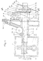
- the reel comprises a frame 1 which supports, via bearings 11, a shaft 21.
- This shaft is driven in rotation about its axis 211 by a drive mechanism.
- the shaft 21 is integral with a toothed wheel 22 which meshes with an endless screw 23 driven by a motor.
- a longitudinal channel 212 opening at one end through an axial inlet orifice 213 and through a lateral outlet orifice 214.
- the wire, marked 4 runs in this channel from the inlet port 213 to outlet port 214, both formed outside the frame.
- a winding drum 3 Downstream of the lateral outlet 214 is disposed a winding drum 3 which has a cylindrical surface on which the wire can be wound.
- This drum has a hub which is crossed by the hollow shaft 21 which supports it by means of bearings 31.
- the drum 3 is immobilized in rotation.
- the wire 4 is wound at the periphery of the drum by a roller winding device which is integral in rotation with the hollow shaft 21.
- This device consists of a support 51, wedged on the hollow shaft 21 between the drum and the frame and rollers 52, 53, 54 mounted on this support.
- the central roller 52 rotates around an axis perpendicular to 211 near the outlet orifice 214.
- the peripheral roller 54 rotates around an axis parallel to the axis 211 outside the drum.
- the wire is wound on an intermediate roller 53 which rotates around an axis inclined with respect to 211.
- the planetary movement of the rollers cause the wire to be wound. on the drum.
- the roller winding device also includes a stopper (roller), not shown, which rotates near the cylindrical surface of the drum so as to stop the last wound turn and consequently to push back (in the direction of the arrow) the turns already rolled up.
- a stopper roller
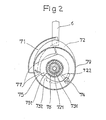
- the drum 3 carries, on the discharge side and above the hub, a star wheel 6 which rotates around a horizontal axis of rotation 61. This star wheel rotates between pads 8 which are fixed and which immobilize this makes the drum 3 in rotation.
- the star wheel 6 receives jerky pulses from a drive cam 71 rotatably coupled to the hollow shaft 21 by means of clutch and declutching means.
- the hollow shaft 21 is integral in rotation with a plate 73 which is housed between a plate 72 carrying the cam 71 and the drum hub. This plate 73 is provided with a cylindrical axis 731 coaxial with 211.
- the cam 71 is mounted on the plate 72 which is guided in rotation coaxially with the hollow shaft 21.
- the plate 72 is integral with a cylindrical tube 721 which acts as a bearing by swiveling on the axis 731.
- the plate 72 and plate 73 are immobilized in translation with respect to each other by a washer 78 screwed on the axis 731.
- the plate 72 serving to support the cam 71 is capable of being coupled and uncoupled in rotation with the hollow shaft 21 by means of clutching and disengaging.
- the plate 73 is provided at its periphery with a notch 732 whose position relative to the roller 54 allows synchronization between the fall of a turn of wire and the stopping time of the star wheel.
- the plate 72 carrying the cam 71 is provided with a radial notch 722 serving as a slide for a movable lock 74 which is subjected to at least one return spring 77 tending to move it towards the center so as to engage it in the peripheral notch 732.
- the cam holder plate 72 is fixed in rotation with the plate 73 and therefore with the hollow shaft 21. Conversely, when the latch 74 is released from the notch 732 , the two plates 73 and 72 are free to rotate relative to each other.
- a declutching cam 75 used to unlock the latch 74 is disposed next to the plate 72. It is integral with a tube 751 in which is housed a cylindrical friction ring 76 which is engaged on the tube 721.
- the cam is guided in rotation about the axis 211 by the tube 751 so that it can be turned manually.
- the rotation of the cam moves the lock 74 radially between a central position where the - lock 74 is engaged in the notch 732 so as to secure in rotation the plates 72 and 73 and a more eccentric position (shown in Figure 2) where the latch 74 is released from the notch 732 so as to disengage in rotation the plates 72 and 73.
- the friction ring 76 makes it possible to stabilize the disengaged position of the cam 75 and serves as its lateral stop.
- the cam 75 is housed in a housing 79.
- the tube 751 protrudes from this housing so as to allow the cam to be maneuvered.
- the drum 3 carries, on the discharge side, inclined ramps 32 which serve to guide the turns which are discharged.
- the cam holder plate 72 When the latch 74 is engaged in the notch 732, the cam holder plate 72 is rotated. By turning the cam 71 rubs at the rear (outside side) of a lower branch of the star wheel and pushes this lower branch towards the drum. The star wheel turns in the direction of the arrow and it carries a turn by a notch which, when released, slides on the ramps 32.
- the clutch means could be constituted by a friction clutch.
Landscapes
- Engineering & Computer Science (AREA)
- Mechanical Engineering (AREA)
- Storage Of Web-Like Or Filamentary Materials (AREA)
- Storing, Repeated Paying-Out, And Re-Storing Of Elongated Articles (AREA)
- Winding Filamentary Materials (AREA)
- Mechanical Operated Clutches (AREA)
- Coiling Of Filamentary Materials In General (AREA)
- Wire Processing (AREA)
Priority Applications (1)
| Application Number | Priority Date | Filing Date | Title |
|---|---|---|---|
| AT83401770T ATE20037T1 (de) | 1982-09-10 | 1983-09-09 | Stationaere aufwickelvorrichtung fuer metalldraht. |
Applications Claiming Priority (2)
| Application Number | Priority Date | Filing Date | Title |
|---|---|---|---|
| FR8215326A FR2532921A1 (fr) | 1982-09-10 | 1982-09-10 | Enrouleur statique de fil metallique |
| FR8215326 | 1982-09-10 |
Publications (2)
| Publication Number | Publication Date |
|---|---|
| EP0104985A1 EP0104985A1 (fr) | 1984-04-04 |
| EP0104985B1 true EP0104985B1 (fr) | 1986-05-28 |
Family
ID=9277344
Family Applications (1)
| Application Number | Title | Priority Date | Filing Date |
|---|---|---|---|
| EP83401770A Expired EP0104985B1 (fr) | 1982-09-10 | 1983-09-09 | Enrouleur statique de fil métallique |
Country Status (4)
| Country | Link |
|---|---|
| EP (1) | EP0104985B1 (enExample) |
| AT (1) | ATE20037T1 (enExample) |
| DE (1) | DE3363778D1 (enExample) |
| FR (1) | FR2532921A1 (enExample) |
Families Citing this family (1)
| Publication number | Priority date | Publication date | Assignee | Title |
|---|---|---|---|---|
| CN103464522B (zh) * | 2013-09-15 | 2015-07-29 | 无锡平盛科技有限公司 | 象鼻式收线机上的出线导轮组件 |
Family Cites Families (8)
| Publication number | Priority date | Publication date | Assignee | Title |
|---|---|---|---|---|
| GB191314294A (en) * | 1913-06-20 | 1914-06-18 | Nicholas King Turnbull | Improvements in Drums for Wire Drawing Machinery. |
| GB712799A (en) * | 1952-07-15 | 1954-07-28 | Herman Bocher | Improvements in and relating to wire winding blocks |
| BE539886A (enExample) * | 1954-07-16 | |||
| GB991055A (en) * | 1963-05-02 | 1965-05-05 | Barron & Crowther Ltd | Improvements in wire coiling or drawing machines |
| DE1285435C2 (de) * | 1966-02-17 | 1973-10-04 | Schloemann Ag | Drehrohrhaspel zum ablegen von draht auf eine foerdereinrichtung |
| DE1602355A1 (de) * | 1967-02-04 | 1970-08-27 | Schloemann Ag | Verfahren zum Ablegen von einem kontinuierlichen Drahtwindungsstrang auf ein mit horizontal angeordneter Foerderebene ausgebildetes Foerdermittel |
| FR2091882B1 (enExample) * | 1970-03-26 | 1974-03-15 | Telecommunications Sa | |
| NL7612811A (nl) * | 1976-11-17 | 1978-05-19 | Rueti Te Strake Bv | Inrichting voor het vormen van een voorraadwikkel uit een van een garenvoorraad aangevoerde draad. |
-
1982
- 1982-09-10 FR FR8215326A patent/FR2532921A1/fr active Granted
-
1983
- 1983-09-09 EP EP83401770A patent/EP0104985B1/fr not_active Expired
- 1983-09-09 DE DE8383401770T patent/DE3363778D1/de not_active Expired
- 1983-09-09 AT AT83401770T patent/ATE20037T1/de not_active IP Right Cessation
Also Published As
| Publication number | Publication date |
|---|---|
| FR2532921B1 (enExample) | 1985-01-18 |
| FR2532921A1 (fr) | 1984-03-16 |
| ATE20037T1 (de) | 1986-06-15 |
| DE3363778D1 (en) | 1986-07-03 |
| EP0104985A1 (fr) | 1984-04-04 |
Similar Documents
| Publication | Publication Date | Title |
|---|---|---|
| EP0871390B1 (fr) | Appareil distributeur de materiaux d'essuyage pouvant etre distribues sous forme pliee ou non pliee | |
| US4813627A (en) | Rewindable hose reel | |
| CH650060A5 (fr) | Dispositif auxiliaire de commande, pour portes ou grilles enroulables ou portes sectionnelles | |
| FR2489155A1 (fr) | Dispositif de blocage du ruban de ceinture pour les ceintures de securite des vehicules automobiles | |
| FR2546225A1 (fr) | Dispositif d'entrainement d'une banne de protection | |
| EP0104985B1 (fr) | Enrouleur statique de fil métallique | |
| FR2477888A1 (fr) | Enrouleur automatique pour une ceinture de securite | |
| FR3000165A1 (fr) | Dispositif de transmission automatiquement embrayable et debrayable | |
| EP0229736A1 (fr) | Dispositif pour recouvrir un corps cylindrique d'une bande d'un matériau de protection | |
| WO2019162380A1 (fr) | Système d'entrainement en rotation d'un organe d'enroulement | |
| EP0838071B1 (fr) | Appareil de distribution automatique de feuille de conditionnement | |
| FR2552409A1 (fr) | Dispositif porte-bobine | |
| FR2544825A1 (fr) | Dispositif de commande selective du mouvement de rotation d'un arbre | |
| WO2008025810A1 (fr) | Dispositif pour annuler la torsion d'un lien entre une extremite fixe et une extremite tournante | |
| FR2646684A1 (fr) | Mecanisme d'enroulement et de deroulement d'un store autour d'un rouleau horizontal | |
| FR2468667A1 (fr) | Dispositif de commande s'un systeme d'etirage de meches de fibres | |
| FR2670897A1 (fr) | Dispositif pour vehiculer rapidement et avec precision une source entre une position de travail et une position de repli. | |
| FR3090024A1 (fr) | Dispositif d’enroulement d’une bâche à barres pour piscine et procédé d’enroulement | |
| EP0995392B1 (fr) | Enrouleur de cordon électrique pour appareils électroménager | |
| FR2678695A1 (fr) | Dispositif d'entrainement selectif d'un arbre de sortie au moyen d'un arbre moteur et machine pour distribuer les fourrages, qui en est equipee. | |
| EP0190531A1 (fr) | Procédé et dispositif pour le stockage, le transfert et la distribution d'objets | |
| EP0299837B1 (fr) | Dispositif capteur mobile pour système d'aspiration centralisée | |
| CH372557A (fr) | Appareil ascenseur-descenseur individuel | |
| FR2706878A1 (en) | Stop and rapid-return device for a tie rolling-up machine | |
| WO2021074520A1 (fr) | Treuil pour la manutention, en particulier pour le levage, de charge |
Legal Events
| Date | Code | Title | Description |
|---|---|---|---|
| PUAI | Public reference made under article 153(3) epc to a published international application that has entered the european phase |
Free format text: ORIGINAL CODE: 0009012 |
|
| AK | Designated contracting states |
Designated state(s): AT BE CH DE FR GB IT LI LU NL SE |
|
| 17P | Request for examination filed |
Effective date: 19840302 |
|
| GRAA | (expected) grant |
Free format text: ORIGINAL CODE: 0009210 |
|
| AK | Designated contracting states |
Kind code of ref document: B1 Designated state(s): AT BE CH DE FR GB IT LI LU NL SE |
|
| REF | Corresponds to: |
Ref document number: 20037 Country of ref document: AT Date of ref document: 19860615 Kind code of ref document: T |
|
| ITF | It: translation for a ep patent filed | ||
| REF | Corresponds to: |
Ref document number: 3363778 Country of ref document: DE Date of ref document: 19860703 |
|
| PGFP | Annual fee paid to national office [announced via postgrant information from national office to epo] |
Ref country code: AT Payment date: 19860820 Year of fee payment: 4 |
|
| PG25 | Lapsed in a contracting state [announced via postgrant information from national office to epo] |
Ref country code: LU Free format text: LAPSE BECAUSE OF NON-PAYMENT OF DUE FEES Effective date: 19860930 |
|
| PLBE | No opposition filed within time limit |
Free format text: ORIGINAL CODE: 0009261 |
|
| STAA | Information on the status of an ep patent application or granted ep patent |
Free format text: STATUS: NO OPPOSITION FILED WITHIN TIME LIMIT |
|
| 26N | No opposition filed | ||
| PGFP | Annual fee paid to national office [announced via postgrant information from national office to epo] |
Ref country code: NL Payment date: 19870930 Year of fee payment: 5 |
|
| PG25 | Lapsed in a contracting state [announced via postgrant information from national office to epo] |
Ref country code: GB Effective date: 19890909 Ref country code: AT Effective date: 19890909 |
|
| PG25 | Lapsed in a contracting state [announced via postgrant information from national office to epo] |
Ref country code: SE Effective date: 19890910 |
|
| PG25 | Lapsed in a contracting state [announced via postgrant information from national office to epo] |
Ref country code: LI Effective date: 19890930 Ref country code: CH Effective date: 19890930 Ref country code: BE Effective date: 19890930 |
|
| BERE | Be: lapsed |
Owner name: SOCIETE METALLURGIQUE DE NORMANDIE Effective date: 19890930 |
|
| PG25 | Lapsed in a contracting state [announced via postgrant information from national office to epo] |
Ref country code: NL Effective date: 19900401 |
|
| GBPC | Gb: european patent ceased through non-payment of renewal fee | ||
| NLV4 | Nl: lapsed or anulled due to non-payment of the annual fee | ||
| PG25 | Lapsed in a contracting state [announced via postgrant information from national office to epo] |
Ref country code: FR Effective date: 19900531 |
|
| REG | Reference to a national code |
Ref country code: CH Ref legal event code: PL |
|
| PG25 | Lapsed in a contracting state [announced via postgrant information from national office to epo] |
Ref country code: DE Effective date: 19900601 |
|
| REG | Reference to a national code |
Ref country code: FR Ref legal event code: ST |
|
| EUG | Se: european patent has lapsed |
Ref document number: 83401770.9 Effective date: 19900521 |