EP0104945A2 - Rollenschienenanlage für Frachtladesystem - Google Patents
Rollenschienenanlage für Frachtladesystem Download PDFInfo
- Publication number
- EP0104945A2 EP0104945A2 EP83305811A EP83305811A EP0104945A2 EP 0104945 A2 EP0104945 A2 EP 0104945A2 EP 83305811 A EP83305811 A EP 83305811A EP 83305811 A EP83305811 A EP 83305811A EP 0104945 A2 EP0104945 A2 EP 0104945A2
- Authority
- EP
- European Patent Office
- Prior art keywords
- track
- rail
- tension
- lug
- roller
- Prior art date
- Legal status (The legal status is an assumption and is not a legal conclusion. Google has not performed a legal analysis and makes no representation as to the accuracy of the status listed.)
- Granted
Links
Images

Classifications
-
- B—PERFORMING OPERATIONS; TRANSPORTING
- B64—AIRCRAFT; AVIATION; COSMONAUTICS
- B64D—EQUIPMENT FOR FITTING IN OR TO AIRCRAFT; FLIGHT SUITS; PARACHUTES; ARRANGEMENT OR MOUNTING OF POWER PLANTS OR PROPULSION TRANSMISSIONS IN AIRCRAFT
- B64D9/00—Equipment for handling freight; Equipment for facilitating passenger embarkation or the like
Definitions
- This invention relates to cargo loading systems for loading palletized cargo into a vehicle such as an aircraft, and more particularly to a roller rail assembly for use in which a system.
- a number of systems have been developed in the prior art for facilitating the loading and unloading of palletized cargo onto and from vehicles such as aircraft.
- a typical such system is described in U.S. Patent No. 3,480,239 to Jensen et al., issued November 25, 1969.
- a roller assembly is shown in connection with Figures 2 and 3 of this patent for facilitating the movement of a pallet into position along the loader. This roller assembly is mounted in a track having alternate lip and cut-out portions by means of a plunger, device which operates in conjunction with a spring mechanism.
- roller rail assembly for use in loading cargo into a vehicle, said roller rail assembly being removably mounted in a track having alternate lip and cut-out 'portions on opposite sides thereof, comprising:
- the improvement of the present invention is achieved by employing a rail member which supports the needed rollers transversely thereof and has a tension stud portion which extends normally therefrom along the bottom edge thereof, this tension stud fitting ino the rack under the lip portions on one side thereof.
- the rail assembly is retained to the track by means of a retainer member which has a longitudinally elongated tension lug and a shear lug of substantially less longitudinal extent than the tension lug, both of these lugs extending substantially in the same direction.
- the retainer member With the tension stud of the rail installed under predetermined lip portions on one side of the track, the retainer member is rotated into a position such that the tension lug of the retainer is installed under the lip portions on the other side of the track, and the shear lug is inserted into a notch in the track between a pair of lip portions. The retainer member is then attached to the rail, thereby firmly retaining the rail to the track.
- roller rail assembly of the present invention provides distinct advntages over that of the prior art in that it eliminates the need for moving parts such as springs, actuated plungers and the like, and is of a simplified construction which is of less weight and can be fabricated for less cost than such assemblies of the prior art.
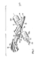
- the rail roller assembly comprises a rail member 11 which has an elongated tension stud or lip 14 which extends substantially normally therefrom along the bottom edge thereof.
- a support shoulder or lip 15 runs along the rail and extends normally therefrom in a direction substantially opposite to that of the tension stud; shoulder 15 being spaced from tension stud 14 towards the centre of the rail and having its longitudinal and transverse axes substantially parallel to those of tension stud 14.
- a plurality of mounting blocks 17 are located in spaced relationship along the top of the rail, each of these mounting blocks having an axle 18 fitted therethrough and fixedly supported thereon, the axles extending transversely outwardly from the opposite sides of the blocks.
- Rotatably supported on each of axles 18 is a pair of rollers 20a and 20b, these rollers being mounted in pairs on opposite sides of the rail and maintained on the axles by means of washers 22 and cotter pins 23.
- Retainer member 26 has a main body portion 26a.
- An elongated tension lug 26b extends normally outwardly from the main body portion and runs longitudinally along the bottom edge thereof.
- a shear lug 26c extends normally from the main body portion of the retainer directly above and opposite tension lug 26b in substantially the same direction as the tension lug; shear lug 26c being substantially less in longitudinal extent than the tension lug.
- a plurality of roller assemblies 20a, 20b are typically supported on a single rail 11 as shown in Figure 3.
- the rail is installed in a track 32 in the following manner.
- the tension stud 14 of the rail is first inserted in position under the lip portion 32a on one side of the track with the shoulder or lip 15 running along the track directly opposite lip portions 32b on the opposite side of the track.
- a retainer member 26 is vertically rotated into position in each of the slots 15a with the tension lug 26b fitted under a number of lip portions 32b of the track and with shear lug 26c fitted in one of the cut-out portions 32c of the track between a pair of lip portions thereof.
- the body portion 26a of the retainer is bolted to the rail by means of bolt 37 and nut 38. In this manner, the roller rail assembly is firmly retained to the track, yet can readily be removed therefrom when required.
Landscapes
- Engineering & Computer Science (AREA)
- Aviation & Aerospace Engineering (AREA)
- Connection Of Plates (AREA)
- Seats For Vehicles (AREA)
Applications Claiming Priority (2)
| Application Number | Priority Date | Filing Date | Title |
|---|---|---|---|
| US06/426,743 US4462493A (en) | 1982-09-29 | 1982-09-29 | Roller rail assembly for cargo loading system |
| US426743 | 1995-04-21 |
Publications (3)
| Publication Number | Publication Date |
|---|---|
| EP0104945A2 true EP0104945A2 (de) | 1984-04-04 |
| EP0104945A3 EP0104945A3 (en) | 1986-02-05 |
| EP0104945B1 EP0104945B1 (de) | 1988-12-07 |
Family
ID=23692027
Family Applications (1)
| Application Number | Title | Priority Date | Filing Date |
|---|---|---|---|
| EP83305811A Expired EP0104945B1 (de) | 1982-09-29 | 1983-09-28 | Rollenschienenanlage für Frachtladesystem |
Country Status (3)
| Country | Link |
|---|---|
| US (1) | US4462493A (de) |
| EP (1) | EP0104945B1 (de) |
| DE (1) | DE3378626D1 (de) |
Cited By (1)
| Publication number | Priority date | Publication date | Assignee | Title |
|---|---|---|---|---|
| US4699337A (en) * | 1985-04-04 | 1987-10-13 | Short Brothers Plc | Cargo handling system for aircraft |
Families Citing this family (15)
| Publication number | Priority date | Publication date | Assignee | Title |
|---|---|---|---|---|
| US4696609A (en) * | 1986-04-21 | 1987-09-29 | Ancra Corporation | Pallet restraint mechanism for cargo loading system |
| US4824050A (en) * | 1987-07-02 | 1989-04-25 | The Boeing Company | Cargo tray for use in aircraft |
| US4875645A (en) * | 1987-07-02 | 1989-10-24 | The Boeing Company | Modular cargo conveyor and restraint system for aircraft |
| US4823927A (en) * | 1987-08-24 | 1989-04-25 | Ancra Corporation | Retractable roller system for cargo handling |
| US5064045A (en) * | 1989-07-12 | 1991-11-12 | Fmc Corporation | Material handling conveyor |
| US5098038A (en) * | 1991-06-19 | 1992-03-24 | Lucas Western Inc. | Retractable guide apparatus |
| DE9313937U1 (de) * | 1993-09-15 | 1995-01-26 | Schall, Eberhard, Dipl.-Volksw., 71364 Winnenden | Stützrolle |
| US5609240A (en) * | 1995-10-23 | 1997-03-11 | Ancra International Corporation | Convertible roller assembly for loading cargo in vehicle |
| US5738199A (en) * | 1995-11-22 | 1998-04-14 | Ancra International Corporation | Diverter roller assembly for loading and unloading cargo in a vehicle |
| US6354424B1 (en) | 2000-06-01 | 2002-03-12 | Ancra International, Llc. | Brake roller for use in roller tray assembly for loading and unloading cargo |
| DE102004014745B4 (de) * | 2004-03-22 | 2009-01-02 | Telair International Gmbh | Frachtdeck |
| WO2006084231A1 (en) * | 2005-02-04 | 2006-08-10 | Span Tech Llc | Reduced friction roller support for modular link conveyor chain |
| US7448836B2 (en) * | 2005-04-22 | 2008-11-11 | D B Industries, Inc. | Load containment netting system |
| US7748510B2 (en) * | 2007-02-27 | 2010-07-06 | The Boeing Company | Torque tube apparatus for moving cargo |
| US8371011B2 (en) * | 2010-09-22 | 2013-02-12 | Toyota Motor Engineering & Manufacturing North America, Inc. | Automated systems for roller rail disassembly and methods of disassembling roller rail assemblies |
Family Cites Families (5)
| Publication number | Priority date | Publication date | Assignee | Title |
|---|---|---|---|---|
| US3251489A (en) * | 1963-02-11 | 1966-05-17 | American Mach & Foundry | Cargo handling apparatus |
| US3381921A (en) * | 1967-01-03 | 1968-05-07 | Boeing Co | Quick change system for passenger and cargo carrying aircraft |
| US3480239A (en) * | 1967-02-23 | 1969-11-25 | Tridair Industries | Quick change system |
| US3422508A (en) * | 1967-06-22 | 1969-01-21 | Davis Aircraft Products Inc | Fitting for cargo tiedown gear |
| US4239100A (en) * | 1978-03-02 | 1980-12-16 | Unarco Industries, Inc. | Package flow system |
-
1982
- 1982-09-29 US US06/426,743 patent/US4462493A/en not_active Expired - Lifetime
-
1983
- 1983-09-28 EP EP83305811A patent/EP0104945B1/de not_active Expired
- 1983-09-28 DE DE8383305811T patent/DE3378626D1/de not_active Expired
Cited By (1)
| Publication number | Priority date | Publication date | Assignee | Title |
|---|---|---|---|---|
| US4699337A (en) * | 1985-04-04 | 1987-10-13 | Short Brothers Plc | Cargo handling system for aircraft |
Also Published As
| Publication number | Publication date |
|---|---|
| DE3378626D1 (en) | 1989-01-12 |
| EP0104945B1 (de) | 1988-12-07 |
| US4462493A (en) | 1984-07-31 |
| EP0104945A3 (en) | 1986-02-05 |
Similar Documents
| Publication | Publication Date | Title |
|---|---|---|
| EP0104945A2 (de) | Rollenschienenanlage für Frachtladesystem | |
| EP0106591B1 (de) | Seitenführungsanlage für Frachtladesystem | |
| US3262588A (en) | Cargo handling apparatus | |
| US3204581A (en) | Cargo locking mechanism | |
| LT3157B (en) | Bogies for railway vehicles with variable gap between wheels | |
| US4742777A (en) | Double mono-cable aerial transportation system | |
| US4418817A (en) | Conveyor chain having carrier rollers | |
| AT403147B (de) | Mechanischer seilentgleisungsschutz | |
| DE69800837T2 (de) | WAGENFAHRGESTELL, INSBESONDERE FüR EINEN SERVIERWAGEN UND EIN MIT EINEM DERARTIGEN FAHRGESTELL VERSEHENER WAGEN | |
| AT403786B (de) | Anlage zum transport von personen und bzw. oder von gütern | |
| DE2243315B2 (de) | Ruecklaufsperre fuer lasttraeger von schleppkreisfoerderern | |
| US5618139A (en) | Outboard roller restrainer for handling cargo in vehicle | |
| CN109677439B (zh) | 制动装置、转向架及车辆 | |
| US4771697A (en) | Load carrier for power and free conveyor | |
| US3197190A (en) | Vehicle coil spring stiffener | |
| DE69110628T2 (de) | Verbessertes Materialfördersystem unter Verwendung von angetriebenen Wagen auf einer Hängebahnschiene. | |
| EP0104946B1 (de) | Sperranlage für Frachtladesystem | |
| DE2155668B2 (de) | Gelenkige Aufhängung eines Lastträgers eines Hängeschleppförderers | |
| DE4123607C1 (de) | ||
| US5241911A (en) | Conveyor system including a support rail with travel surfaces for driven support wheels of vehicles | |
| EP0214669A2 (de) | Vorrichtung zum Transportieren von Stückgut | |
| CN113650794A (zh) | 用于飞行器的燃油箱系统和用于安装飞行器的燃油箱的方法 | |
| EP0288730B1 (de) | Vorrichtung zum Fördern und Speichern von Gegenständen | |
| US4505459A (en) | Leaf spring assembly for a vehicle | |
| DE3000641A1 (de) | Sortierwagen |
Legal Events
| Date | Code | Title | Description |
|---|---|---|---|
| PUAI | Public reference made under article 153(3) epc to a published international application that has entered the european phase |
Free format text: ORIGINAL CODE: 0009012 |
|
| AK | Designated contracting states |
Designated state(s): DE FR GB |
|
| PUAL | Search report despatched |
Free format text: ORIGINAL CODE: 0009013 |
|
| AK | Designated contracting states |
Designated state(s): DE FR GB |
|
| 17P | Request for examination filed |
Effective date: 19860730 |
|
| 17Q | First examination report despatched |
Effective date: 19870430 |
|
| GRAA | (expected) grant |
Free format text: ORIGINAL CODE: 0009210 |
|
| AK | Designated contracting states |
Kind code of ref document: B1 Designated state(s): DE FR GB |
|
| REF | Corresponds to: |
Ref document number: 3378626 Country of ref document: DE Date of ref document: 19890112 |
|
| ET | Fr: translation filed | ||
| PLBE | No opposition filed within time limit |
Free format text: ORIGINAL CODE: 0009261 |
|
| STAA | Information on the status of an ep patent application or granted ep patent |
Free format text: STATUS: NO OPPOSITION FILED WITHIN TIME LIMIT |
|
| 26N | No opposition filed | ||
| REG | Reference to a national code |
Ref country code: FR Ref legal event code: TP |
|
| REG | Reference to a national code |
Ref country code: GB Ref legal event code: 732 |
|
| REG | Reference to a national code |
Ref country code: FR Ref legal event code: GC |
|
| REG | Reference to a national code |
Ref country code: GB Ref legal event code: 732 |
|
| REG | Reference to a national code |
Ref country code: GB Ref legal event code: IF02 |
|
| PGFP | Annual fee paid to national office [announced via postgrant information from national office to epo] |
Ref country code: GB Payment date: 20020925 Year of fee payment: 20 Ref country code: FR Payment date: 20020925 Year of fee payment: 20 |
|
| PGFP | Annual fee paid to national office [announced via postgrant information from national office to epo] |
Ref country code: DE Payment date: 20021002 Year of fee payment: 20 |
|
| PG25 | Lapsed in a contracting state [announced via postgrant information from national office to epo] |
Ref country code: GB Free format text: LAPSE BECAUSE OF EXPIRATION OF PROTECTION Effective date: 20030927 |
|
| REG | Reference to a national code |
Ref country code: GB Ref legal event code: PE20 |