EP0106591B1 - Seitenführungsanlage für Frachtladesystem - Google Patents
Seitenführungsanlage für Frachtladesystem Download PDFInfo
- Publication number
- EP0106591B1 EP0106591B1 EP83305812A EP83305812A EP0106591B1 EP 0106591 B1 EP0106591 B1 EP 0106591B1 EP 83305812 A EP83305812 A EP 83305812A EP 83305812 A EP83305812 A EP 83305812A EP 0106591 B1 EP0106591 B1 EP 0106591B1
- Authority
- EP
- European Patent Office
- Prior art keywords
- arm portion
- frame
- side guide
- guide assembly
- accordance
- Prior art date
- Legal status (The legal status is an assumption and is not a legal conclusion. Google has not performed a legal analysis and makes no representation as to the accuracy of the status listed.)
- Expired
Links
- 230000000717 retained effect Effects 0.000 claims description 4
- 238000010276 construction Methods 0.000 description 2
- 230000000712 assembly Effects 0.000 description 1
- 238000000429 assembly Methods 0.000 description 1
Images

Classifications
-
- B—PERFORMING OPERATIONS; TRANSPORTING
- B64—AIRCRAFT; AVIATION; COSMONAUTICS
- B64C—AEROPLANES; HELICOPTERS
- B64C1/00—Fuselages; Constructional features common to fuselages, wings, stabilising surfaces or the like
- B64C1/18—Floors
- B64C1/20—Floors specially adapted for freight
-
- B—PERFORMING OPERATIONS; TRANSPORTING
- B64—AIRCRAFT; AVIATION; COSMONAUTICS
- B64D—EQUIPMENT FOR FITTING IN OR TO AIRCRAFT; FLIGHT SUITS; PARACHUTES; ARRANGEMENT OR MOUNTING OF POWER PLANTS OR PROPULSION TRANSMISSIONS IN AIRCRAFT
- B64D9/00—Equipment for handling freight; Equipment for facilitating passenger embarkation or the like
- B64D9/003—Devices for retaining pallets or freight containers
Definitions
- This invention relates to cargo loading systems for loading palletized cargo into a vehicle such as an aircraft, and more particularly to a side guide roller assembly for use in such a system.
- a side guide assembly is shown and described in connection with Figures 5 and 6 of this patent for guiding the longitudinal movement of the pallet and limiting outward transverse movement thereof.
- This side guide assembly employs a spring- actuated plunger member which fits into the track which operates in conjunction with a supporting leg and roller members to provide the desired transverse restraint and longitudinal freedom of movement of the pallets.
- U.S. Patent No. 3,334,718 discloses cargo handling apparatus in accordance with the features of the preamble of claim 1 which comprises a plurality of trays with rollers mounted on the trays. A plurality of T-shaped guide members are attached to the trays.
- Each guide member comprises an elongated arm portion extending from the head of the guide member.
- a guide plate on the head extends at right angles to the longitudinal axis of the arm portion. The guide plate guides pallets along the rollers.
- the elongated arm portion is attached by a retainer stud at one end to the floor of the vehicle in which the apparatus is in use.
- the head of the guide member is attached to the track by attach- mentfittings underthe lip portions of alternate cut-out and lip portions on the track.
- a side guide assembly for guiding a pallet for loading in a vehicle, said side guide assembly being mounted in a track member having alternate cut-out and lip portions, comprising:
- a frame having an elongated arm portion, a first end of said arm portion having a portion to be retained to the floor,
- the improvement of the present invention is achieved by employing the tensioning lug means which operates in conjunction with the shear lug meansto retain one end of the assembly in the track while the otherend of the assembly has an opening formed therein which is retained to the floor of the vehicle over the stud member mounted on such floor.
- the assembly of the present invention can readily be moved into a mounting position by a rocking motion, i.e., placing the tensioning lug means under the lips of the track member with the assembly in an upwardly tilted position and then lowering the assembly to bring the shear lug means into the cut-out portions of the track in abutment against the sides thereof, with the opening portion of the assembly fitted onto the stud mounted in the vehicle floor and retained thereto.
- the side guide assembly of the present invention provides distinct advantages over that of the prior art in that it eliminates the need for moving parts such as spring actuated plungers and the like and is of a simple, one-piece construction of lower weight and less cost than such assemblies of the prior art.
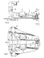
- the side guide assembly includes a main frame 11.
- the frame has an elongated arm 12 which has an opening portion 12a defining an opening at one extreme end thereof and a pair of cross arms 14 between which a pair of roller members 16 are rotatably supported.
- a guide plate 18 extends upwardly from arm 12 near one end thereof and an overhanging member 20 extends inwardly at substantially right angles to guide plate 18, guide plate 18 and overhanging member 20 functioning to guide a pallet for longitudinal movement on rollers 16.
- tension lugs 25 Extending from cross arm 15, directly above tension lug 25 and running in substantially the opposite direction thereas, are a pair of shear lugs 27.
- the side guide assembly is installed in the track 35 as shown in Figure 2 by inserting tension lugs 25 into track 35 under the lip portions 35a of the scalloped track, with the device angled relative to the track as shown in Figures 2 and 3.
- the side guide assembly is then rocked down into position with shear lugs 27 inserted in the cut-out portions 35b of the track and in abutment thereagainst.
- opening portion 12a of arm 12 fits over stud 40 which is fixedly mounted in the floor of the vehicle in a keyhole adapter 19 installed in such floor.
- Stud 40 has a threaded top portion 40a on which a nut 41 is threadably tightened to retain the side guide in position in the track.
- the stud further has flattened sides 40b which abut against similarly flattened side portions of opening portion 12a.
Landscapes
- Engineering & Computer Science (AREA)
- Aviation & Aerospace Engineering (AREA)
- Mechanical Engineering (AREA)
- Pallets (AREA)
- Body Structure For Vehicles (AREA)
Claims (8)
Applications Claiming Priority (2)
| Application Number | Priority Date | Filing Date | Title |
|---|---|---|---|
| US06/426,761 US4530483A (en) | 1982-09-30 | 1982-09-30 | Side guide for cargo loading system |
| US426761 | 1982-09-30 |
Publications (4)
| Publication Number | Publication Date |
|---|---|
| EP0106591A2 EP0106591A2 (de) | 1984-04-25 |
| EP0106591A3 EP0106591A3 (en) | 1986-02-05 |
| EP0106591B1 true EP0106591B1 (de) | 1988-05-11 |
| EP0106591B2 EP0106591B2 (de) | 1992-02-12 |
Family
ID=23692094
Family Applications (1)
| Application Number | Title | Priority Date | Filing Date |
|---|---|---|---|
| EP83305812A Expired EP0106591B2 (de) | 1982-09-30 | 1983-09-28 | Seitenführungsanlage für Frachtladesystem |
Country Status (3)
| Country | Link |
|---|---|
| US (1) | US4530483A (de) |
| EP (1) | EP0106591B2 (de) |
| DE (1) | DE3376548D1 (de) |
Families Citing this family (16)
| Publication number | Priority date | Publication date | Assignee | Title |
|---|---|---|---|---|
| US4875645A (en) * | 1987-07-02 | 1989-10-24 | The Boeing Company | Modular cargo conveyor and restraint system for aircraft |
| DE3733406A1 (de) * | 1987-10-02 | 1989-04-13 | Bavaria Cargo Tech | Fuehrungseinrichtung fuer eine foerderbahn |
| USD388393S (en) * | 1995-02-27 | 1997-12-30 | Ancra International Corporation | Restraint device for cargo handling |
| DE19812014C1 (de) * | 1998-03-19 | 1999-08-19 | Daimler Chrysler Aerospace | Riegelelement zum Arretieren von Frachtgütern innerhalb eines Frachtladesystems, insbesondere in einem Flugzeug |
| US6047940A (en) * | 1998-04-13 | 2000-04-11 | Kaplan; Charles | Removably fixed and restorable auditorium seating |
| US6806842B2 (en) | 2000-07-18 | 2004-10-19 | Marconi Intellectual Property (Us) Inc. | Wireless communication device and method for discs |
| US7098850B2 (en) | 2000-07-18 | 2006-08-29 | King Patrick F | Grounded antenna for a wireless communication device and method |
| US6483473B1 (en) * | 2000-07-18 | 2002-11-19 | Marconi Communications Inc. | Wireless communication device and method |
| US6974288B2 (en) * | 2004-02-12 | 2005-12-13 | Portec Rail Products Inc. | Cushioned banding anchor |
| GB2466801A (en) * | 2009-01-07 | 2010-07-14 | Unwin C N Ltd | Anchorage system for fixing articles to vehicle floor rail |
| US8221038B1 (en) | 2010-02-26 | 2012-07-17 | Angra International, LLC. | Overridable side lock (stabber) pallet type load restraint |
| US8337127B2 (en) | 2011-04-26 | 2012-12-25 | Ancra International, Llc | Latch arrangement for cargo restraint |
| US8845249B2 (en) | 2013-01-14 | 2014-09-30 | Ancra International Llc | Quick release device |
| PL3169296T3 (pl) * | 2014-07-18 | 2019-04-30 | Ferno Washington | System montowania sprzętu |
| US9475581B2 (en) * | 2014-10-08 | 2016-10-25 | Goodrich Corporation | Adjustable restraint assemblies |
| KR101845299B1 (ko) | 2016-11-22 | 2018-04-04 | 한국항공우주연구원 | 무인 비행체 날개 |
Family Cites Families (9)
| Publication number | Priority date | Publication date | Assignee | Title |
|---|---|---|---|---|
| US2893677A (en) * | 1957-08-12 | 1959-07-07 | Naomi L Dannenburg | Hospital bed standard support |
| US3111912A (en) * | 1962-01-31 | 1963-11-26 | Gen Electric | Roller assembly for operation on a rail |
| US3251489A (en) * | 1963-02-11 | 1966-05-17 | American Mach & Foundry | Cargo handling apparatus |
| US3262588A (en) * | 1963-07-19 | 1966-07-26 | American Mach & Foundry | Cargo handling apparatus |
| US3241501A (en) * | 1964-01-08 | 1966-03-22 | Aid Corp | Hold-down device |
| US3480239A (en) * | 1967-02-23 | 1969-11-25 | Tridair Industries | Quick change system |
| US3465995A (en) * | 1968-02-23 | 1969-09-09 | Viber Co | I-beam clamp |
| FR2331507A1 (fr) * | 1975-11-17 | 1977-06-10 | Pelletier Expl Ets H | Verrou pour l'arrimage de fret palettise ou en conteneur dans un vehicule |
| US4077590A (en) * | 1976-03-11 | 1978-03-07 | The Boeing Company | Integrated treadway cargo handling system |
-
1982
- 1982-09-30 US US06/426,761 patent/US4530483A/en not_active Expired - Lifetime
-
1983
- 1983-09-28 EP EP83305812A patent/EP0106591B2/de not_active Expired
- 1983-09-28 DE DE8383305812T patent/DE3376548D1/de not_active Expired
Also Published As
| Publication number | Publication date |
|---|---|
| US4530483A (en) | 1985-07-23 |
| EP0106591A3 (en) | 1986-02-05 |
| DE3376548D1 (en) | 1988-06-16 |
| EP0106591A2 (de) | 1984-04-25 |
| EP0106591B2 (de) | 1992-02-12 |
Similar Documents
| Publication | Publication Date | Title |
|---|---|---|
| EP0106591B1 (de) | Seitenführungsanlage für Frachtladesystem | |
| EP0243137B1 (de) | Mechanismus zum Festhalten von Paletten in Frachtladesystemen | |
| US4462493A (en) | Roller rail assembly for cargo loading system | |
| US3390752A (en) | Cargo handling apparatus | |
| US5316242A (en) | Apparatus for guiding different size pallets, especially on the loading floor of an aircraft | |
| US4331412A (en) | Retractable pallet securing device | |
| EP0323478A1 (de) | Übergabefahrzeug zur vermeidung der anhäufung von fehlern beim abstellen von packstuecken in einem durchlauflager. | |
| US4936623A (en) | Open roof construction for a vehicle | |
| US4462735A (en) | Newspaper live storage buffer | |
| EP0343837A1 (de) | Montageförderer | |
| US5605200A (en) | Self attaching upper radiator mount | |
| CN109677439B (zh) | 制动装置、转向架及车辆 | |
| WO2001056835A1 (en) | Flat goods clamping and transporting apparatus | |
| US5618139A (en) | Outboard roller restrainer for handling cargo in vehicle | |
| US3602474A (en) | Pallet restraint apparatus | |
| CN212268624U (zh) | 一种输送链条故障用推头调整工具 | |
| EP0391301B1 (de) | Vorrichtung zum Laden von Gegenständen auf ein laufendes Förderband | |
| EP0566195A1 (de) | Sicherheitssperrklinke | |
| WO1993001999A1 (en) | Storage and transportation rack for panel parts | |
| US6523671B2 (en) | Conveyor escapement | |
| US5241911A (en) | Conveyor system including a support rail with travel surfaces for driven support wheels of vehicles | |
| US4718350A (en) | Small lightweight driverless vehicle | |
| EP0104946B1 (de) | Sperranlage für Frachtladesystem | |
| US5001987A (en) | Lightweight car-on-track system | |
| US6309014B1 (en) | Roof arrangement |
Legal Events
| Date | Code | Title | Description |
|---|---|---|---|
| PUAI | Public reference made under article 153(3) epc to a published international application that has entered the european phase |
Free format text: ORIGINAL CODE: 0009012 |
|
| AK | Designated contracting states |
Designated state(s): DE FR GB |
|
| PUAL | Search report despatched |
Free format text: ORIGINAL CODE: 0009013 |
|
| AK | Designated contracting states |
Designated state(s): DE FR GB |
|
| 17P | Request for examination filed |
Effective date: 19860730 |
|
| 17Q | First examination report despatched |
Effective date: 19870430 |
|
| GRAA | (expected) grant |
Free format text: ORIGINAL CODE: 0009210 |
|
| AK | Designated contracting states |
Kind code of ref document: B1 Designated state(s): DE FR GB |
|
| REF | Corresponds to: |
Ref document number: 3376548 Country of ref document: DE Date of ref document: 19880616 |
|
| ET | Fr: translation filed | ||
| PLBI | Opposition filed |
Free format text: ORIGINAL CODE: 0009260 |
|
| 26 | Opposition filed |
Opponent name: MESSERSCHMITT - BOELKOW - BLOHM GMBH, OTTOBRUNN Effective date: 19890202 |
|
| REG | Reference to a national code |
Ref country code: FR Ref legal event code: TP |
|
| PUAH | Patent maintained in amended form |
Free format text: ORIGINAL CODE: 0009272 |
|
| STAA | Information on the status of an ep patent application or granted ep patent |
Free format text: STATUS: PATENT MAINTAINED AS AMENDED |
|
| 27A | Patent maintained in amended form |
Effective date: 19920212 |
|
| AK | Designated contracting states |
Kind code of ref document: B2 Designated state(s): DE FR GB |
|
| REG | Reference to a national code |
Ref country code: GB Ref legal event code: 732 |
|
| ET3 | Fr: translation filed ** decision concerning opposition | ||
| REG | Reference to a national code |
Ref country code: FR Ref legal event code: GC |
|
| REG | Reference to a national code |
Ref country code: GB Ref legal event code: 732 |
|
| REG | Reference to a national code |
Ref country code: GB Ref legal event code: IF02 |
|
| PGFP | Annual fee paid to national office [announced via postgrant information from national office to epo] |
Ref country code: GB Payment date: 20020925 Year of fee payment: 20 Ref country code: FR Payment date: 20020925 Year of fee payment: 20 |
|
| PGFP | Annual fee paid to national office [announced via postgrant information from national office to epo] |
Ref country code: DE Payment date: 20021002 Year of fee payment: 20 |
|
| PG25 | Lapsed in a contracting state [announced via postgrant information from national office to epo] |
Ref country code: GB Free format text: LAPSE BECAUSE OF EXPIRATION OF PROTECTION Effective date: 20030927 |
|
| REG | Reference to a national code |
Ref country code: GB Ref legal event code: PE20 |