EP0103746A2 - Dispensing device in the shape of a stick - Google Patents
Dispensing device in the shape of a stick Download PDFInfo
- Publication number
- EP0103746A2 EP0103746A2 EP83108073A EP83108073A EP0103746A2 EP 0103746 A2 EP0103746 A2 EP 0103746A2 EP 83108073 A EP83108073 A EP 83108073A EP 83108073 A EP83108073 A EP 83108073A EP 0103746 A2 EP0103746 A2 EP 0103746A2
- Authority
- EP
- European Patent Office
- Prior art keywords
- sleeve
- dispensing device
- wall
- web
- feed device
- Prior art date
- Legal status (The legal status is an assumption and is not a legal conclusion. Google has not performed a legal analysis and makes no representation as to the accuracy of the status listed.)
- Ceased
Links
Images
Classifications
-
- B—PERFORMING OPERATIONS; TRANSPORTING
- B43—WRITING OR DRAWING IMPLEMENTS; BUREAU ACCESSORIES
- B43K—IMPLEMENTS FOR WRITING OR DRAWING
- B43K21/00—Propelling pencils
- B43K21/02—Writing-core feeding mechanisms
- B43K21/06—Writing-core feeding mechanisms with the writing-cores fed by means sliding in longitudinally-slotted casings
-
- A—HUMAN NECESSITIES
- A45—HAND OR TRAVELLING ARTICLES
- A45D—HAIRDRESSING OR SHAVING EQUIPMENT; EQUIPMENT FOR COSMETICS OR COSMETIC TREATMENTS, e.g. FOR MANICURING OR PEDICURING
- A45D40/00—Casings or accessories specially adapted for storing or handling solid or pasty toiletry or cosmetic substances, e.g. shaving soaps or lipsticks
- A45D40/02—Casings wherein movement of the lipstick or like solid is a sliding movement
-
- A—HUMAN NECESSITIES
- A45—HAND OR TRAVELLING ARTICLES
- A45D—HAIRDRESSING OR SHAVING EQUIPMENT; EQUIPMENT FOR COSMETICS OR COSMETIC TREATMENTS, e.g. FOR MANICURING OR PEDICURING
- A45D40/00—Casings or accessories specially adapted for storing or handling solid or pasty toiletry or cosmetic substances, e.g. shaving soaps or lipsticks
- A45D40/20—Pencil-like cosmetics; Simple holders for handling stick-shaped cosmetics or shaving soap while in use
- A45D40/205—Holders for stick-shaped cosmetics whereby the stick can move axially relative to the holder
- A45D2040/207—Holders for stick-shaped cosmetics whereby the stick can move axially relative to the holder the relative movement being made by an axial action, e.g. by pushing
Definitions
- the invention relates to a rod-shaped dispensing device as defined in the preamble of claim 1.
- Such dispensing devices such as the like for example as sleeves for glue sticks, cosmetic sticks. used are relatively complicated according to the current state of the art. They usually consist of a large number of individual parts and are therefore complex to manufacture. Furthermore, filling the sleeve with the mass to be dispensed is generally cumbersome. In most cases it is not possible to fill the mass directly into the sleeve. The mass must be shaped beforehand, e.g. be poured into molds or pressed. If open parts are present on the mass formed in this way, there is a risk of contamination during further processing, particularly when inserting it into the sleeve.
- This object is achieved by the measures as defined in the characterizing part of patent claim 1.
- the result is a simple and inexpensive to produce dispensing device which offers the desired protection against the emergence or leakage of the mass under the influence of heat or pressure. Through the hit Measures are possible either to fill the mass directly into the dispensing device or to connect it separately to parts of the feed device and then to insert it into the sleeve.
- the dispensing device can be used for various types of material, for example as a sleeve for glue sticks, or cosmetic sticks, such as eye shadows, compact powders or lipsticks. It can just as well be used to dispense, for example, a wax-like carrier mass which contains medicinal or cosmetic active ingredients. Other masses that can be rubbed or wiped away, such as soft crayons or chalk, are also well suited for use in the dispensing device described.
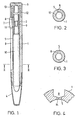
- the sleeve 1 shows a rod-shaped dispensing device, consisting of a cylindrical sleeve 1, a feed device 2 which is longitudinally displaceable therein and an end cap 3 closing the rear part of the sleeve.
- the front part of the sleeve is provided with a removable closure cap 4.
- the sleeve 1 has an essentially longitudinal groove-like wall thinning 5, as shown in FIG. 2 in accordance with the section II-II from FIG. 1.
- On the feed device which in the present example is designed like a piston, a radially extending, preferably wedge-like web 6 is attached, which penetrates the wall thinner 5 and merges into an actuating catch 7.
- the web 6 and / or the actuating catch 7 are preferably guided within the groove 8.
- the feed device 2 is provided with a constriction profile 9, by which the mass 10 to be dispensed is held within the feed device 2.
- the mass 10 is cylindrical pin-shaped in the example and protrudes as far from the front end of the sleeve 1 as is necessary for the correct delivery of the mass by rubbing or wiping.
- the mass 10 may directly in the sleeve 1 from the rear or from beingssen- b racht, wherein the feeding device 2 is located at the rear end. After the mass 10 has hardened, a non-positive connection has formed via the constriction profile 9 between the mass 10 and the piston-like feed device 2. However, the mass 10 can also be connected separately to the feed device 2 or poured or pressed into it and then inserted into the sleeve 1 from behind. The rear sleeve opening is then closed with the end cap 3.
- the web 6 of the feed device 2 preferably has a slightly beveled cutting edge 11. This serves to gently separate the initially closed wall thinner 5 when the mass 10 is pushed in with the aid of the feed device 2.
- the spring action of the sleeve which is held together in the rear part by the end cap 3 and in the front part by the closed wall thinner 5, ensures a tight closure of the wall thinner 5 in the region of the web 6.
- the web 6 also gently tapers at its rear end, for example designed wedge-shaped, so that the sleeve material in the cut part of the wall thinner 5 practically closes the cut part because of the elasticity or spring action of the sleeve material.
- the closure effect and the mechanical stability of the sleeve end is supported by the action of the end cap 3, which in the example shown overlaps the rear end of the sleeve 2.
- the sleeve is provided at the rear end with an outer recess 12, which in the preferred example corresponds to the wall thickness of the end cap 3 in this area.
- the end cap 3 has an inward concentric pin 13, the outside diameter of which corresponds to the inside diameter of the sleeve.
- the sleeve 1 can be made of plastic, for example polyethylene or polypropylene, or of metal, e.g. made of aluminum or another relatively easy to cut material.
- Two sleeves inserted into one another can also be provided, the outer sleeve preferably being designed as a spring sleeve, which ensures cohesion in particular in the rear, cut-open part of the groove 8, and the inner sleeve is made of relatively soft, easily cut material.
- the wall thinner 5 can also be located in the outer wall area of the sleeve 1.
- FIG. 4 it is possible to design the wall thinning, both with an inside wall thinning according to FIG. 2 and with an outside wall thinning according to FIG. 3, so that it does not have a constant wall thickness, but preferably a has weak point 14 located in the central region of the groove 8. This results in a guide for the cutting edge 11 and thus a particularly smooth and clean cut in the central region of the wall thinner 5.
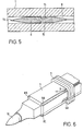
- the feed device 2 If the feed device 2 is to be prevented from sliding back into the rear area of the sleeve 1, the feed device 2, preferably in the area of the web 6, can be provided with barbs 16 according to FIG. 5, which are attached to the sleeve wall, e.g. engage in the area of the groove 8 or in other areas between the sleeve wall and the feed device.
- the actuating catch 7 is designed as a ring enclosing the sleeve, a web 6 preferably being connected to the piston arranged in the interior of the sleeve.
- guide webs 6A are arranged in the area of the grooves 8B and 8C, which do not cut open the sleeve wall in the area of these grooves, but only serve as guides.
- a sleeve can also be used, the wall thinning 5 of which is already open in the manner of a slot and which resiliently or elastically shrinks in the region of the web 6.
- the wall thinner 5 can be along any curve, e.g. be provided along a spiral, the curve extending substantially in the longitudinal direction of the sleeve.
Landscapes
- Containers And Packaging Bodies Having A Special Means To Remove Contents (AREA)
- Coating Apparatus (AREA)
- Mechanical Pencils And Projecting And Retracting Systems Therefor, And Multi-System Writing Instruments (AREA)
Abstract
Stabförmige Dispensiervorrichtung für abreib- oder abstreichbare Massen, beispielsweise Hülse für Klebe-oder Kosmetikstifte, die aus einer äusseren, die Masse umschliessenden Hülse (1) besteht und eine in der Hülse geführte, von aussen betätigbare Vorschubeinrichtung (2) aufweist. Die Hülse ist mit mindestens einer längs der Hülsenachse verlaufenden nut- oder schlitzartigen Wandverdünnung (5) versehen. Die Wandverdünnung wird durch einen Steg (6) durchstossen, der mit der Vorschubeinrichtung (2) in Verbindung steht. Der Steg (6) geht in eine aussenliegende Betätigungsraste (7) über. Beim Betätigen der Raste (7) wird die Wandverdünnung (5) aufgeschlitzt oder aufgeklemmt. Durch schneidenförmige Ausbildung des Stegs (6) und eventuell durch Federwirkung des Hülsenmaterials bleibt der Uebergang zwischen der Wandverdünnung (5) und dem zur Vorschubeinrichtung (2) gehorenden Steg (6) dicht, so dass die Masse (10) im Hülseninnern bleibt und auch bei Wärme- oder Druckeinwirkung nicht nach aussen dringt.Rod-shaped dispensing device for masses which can be rubbed or wiped, for example a sleeve for glue or cosmetic sticks, which consists of an outer sleeve (1) enclosing the mass and which has a feed device (2) which is guided in the sleeve and can be actuated from the outside. The sleeve is provided with at least one groove or slot-like wall thinner (5) running along the sleeve axis. The wall thinner is pierced by a web (6) which is connected to the feed device (2). The web (6) merges into an external actuating catch (7). When the catch (7) is pressed, the wall thinner (5) is slit or clamped on. Due to the cutting-like design of the web (6) and possibly due to the spring action of the sleeve material, the transition between the wall thinner (5) and the web (6) belonging to the feed device (2) remains tight, so that the mass (10) remains inside the sleeve and also at Exposure to heat or pressure does not escape.
Description
Die Erfindung betrifft eine stabförmige Dispensiervorrichtung, wie sie im Oberbegriff des Patentanspruchs 1 definiert ist.The invention relates to a rod-shaped dispensing device as defined in the preamble of
Derartige Dispensiervorrichtungen, wie sie beispielsweise als Hülsen für Klebestifte, Kosmetikstifte o.dgl. verwendet werden, sind nach dem derzeitigen Stand der Technik relativ kompliziert. Sie bestehen in der Regel aus einer Vielzahl von Einzelteilen und sind damit aufwendig in der Herstellung. Ferner ist das Füllen der Hülse mit der abzugebenden Masse in der Regel umständlich. Ein direktes Einfüllen der Masse in die Hülse ist in den meisten Fällen nicht möglich. Die Masse muss vorher geformt, z.B. in Formen gegossen oder gepresst werden. Sind an der so geformten Masse offene Partien vorhanden, besteht bei der Weiterverarbeitung, insbesondere beim Einsetzen in die Hülse, die Gefahr der Verunreinigung.Such dispensing devices, such as the like for example as sleeves for glue sticks, cosmetic sticks. used are relatively complicated according to the current state of the art. They usually consist of a large number of individual parts and are therefore complex to manufacture. Furthermore, filling the sleeve with the mass to be dispensed is generally cumbersome. In most cases it is not possible to fill the mass directly into the sleeve. The mass must be shaped beforehand, e.g. be poured into molds or pressed. If open parts are present on the mass formed in this way, there is a risk of contamination during further processing, particularly when inserting it into the sleeve.
Es ist Aufgabe der vorliegenden Erfindung, eine stabförmige Dispensiervorrichtung gemäss dem Oberbegriff des Patentanspruchs 1 anzugeben, welche einfach und sicher aufgebaut ist, so dass die Vorrichtung einfach und damit preiswert herzustellen ist und einen besonders hohen Schutz gegen Auslaufen oder Heraustreten der Masse unter Temperatur- oder Druckeinwirkung bietet. Diese Aufgabe wird durch die Massnahmen gelöst, wie sie im kennzeichnenden Teil des Patentanspruchs 1 definiert sind. Es ergibt sich eine einfache und preiswert herzustellende Dispensiervorrichtung, welche den gewünschten Schutz gegen Heraustreten oder Auslaufen der Masse unter Wärme- bzw. Druckeinfluss bietet. Durch die getroffenen Massnahmen ist es möglich, entweder die Masse direkt in die Dispensiervorrichtung einzufüllen, oder aber sie separat mit Teilen der Vorschubeinrichtung zu verbinden und anschliessend in die Hülse einzuführen. Besonders vorteilhaft wirkt es sich aus, wenn die nut- oder schlitzartige Oeffnung, die sich in der Hülse unter der Wirkung des Stegs bildet, durch die Federwirkung der Hülse unmittelbar hinter dem Steg wieder geschlossen wird. Dadurch werden auch Reste der Masse, die hinter der Vorschubeinrichtung an der Innenwand der Hülse zurückbleiben könnten, daran gehindert, aus der Hülse herauszutreten. Ferner werden die Herstellung der Dispensiervorrichtung sowie das Einfüllen der abzugebenden Masse wesentlich vereinfacht. Die Dispensiervorrichtung lässt sich für verschiedenartige Massen verwenden, beispielsweise als Hülse für Klebstifte, oder Kosmetikstifte, wie Lidschatten, Kompaktpuder oder Lippenstifte. Ebensogut lässt sie sich zur Abgabe einer beispielsweise wachsartigen Trägermasse verwenden, welche medizinische oder kosmetische Wirkstoffe enthält. Auch andere abreib- oder abstreichbare Massen, wie weiche Zeichenstifte oder Kreide, eignen sich gut zur Verwendung in der beschriebenen Dispensiervorrichtung.It is an object of the present invention to provide a rod-shaped dispensing device according to the preamble of
Im folgenden werden Ausführungsbeispiele der Erfindung anhand der Zeichnung näher erläutert. Es zeigen:
- Fig. 1 die Schnittdarstellung eines ersten Ausführungsbeispiels,
- Fig. 2 den Schnitt II - II gemäss Fig. l,
- Fig. 3 den Schnitt II - II gemäss Fig. 1 für ein zweites Ausführungsbeispiel,
- Fig. 4 den Schnitt II - II gemäss Fig. 1 für ein drittes Ausführungsbeispiel,
- Fig. 5 eine Widerhakenvorrichtung zwischen der Hülse und derVorschubeinrichtung, und
- Fig. 6 die perspektivische Ansicht für ein viertes Ausführungsbeispiel.
- 1 is a sectional view of a first embodiment;
- 2 shows the section II - II according to FIG. 1,
- 3 shows the section II - II according to FIG. 1 for a second embodiment,
- 4 shows the section II - II according to FIG. 1 for a third embodiment,
- Figure 5 shows a barb device between the sleeve and the feed device, and
- Fig. 6 is a perspective view for a fourth embodiment.
Fig. 1 zeigt eine stabförmige Dispensiervorrichtung, bestehend aus einer zylinderförmigen Hülse 1, einer darin längsverschiebbaren Vorschubeinrichtung 2 und einer den hinteren Teil der Hülse verschliessenden Endkappe 3. Der vordere Teil der Hülse ist mit einer abnehmbaren Verschlusskappe 4 versehen. Die Hülse 1 weist eine im wesentlichen in Längsrichtung verlaufende nutartige Wandverdünnung 5 auf, wie dies in Fig. 2 entsprechend dem Schnitt II - II aus Fig. 1 dargestellt ist. An der Vorschubeinrichtung, die im vorliegenden Beispiel kolbenartig ausgebildet ist, ist ein radial verlaufender, vorzugsweise keilartiger Steg 6 angebracht, der die Wandverdünnung 5 durchdringt und in eine Betätigungsraste 7 übergeht. Der Steg 6 und/oder die Betätigungsraste 7 sind vorzugsweise innerhalb der Nut 8 geführt. Die Vorschubeinrichtung 2 ist mit einem Einschnürungsprofil 9 versehen, von welchem die abzugebende Masse 10 innerhalb der Vorschubeinrichtung 2 gehalten wird. Die Masse 10 ist im Beispiel zylinderstiftartig ausgebildet und ragt so weit aus dem vorderen Ende der Hülse 1 heraus, wie dies zur einwandfreien Abgabe der Masse durch Abreiben oder Abstreichen notwendig ist.1 shows a rod-shaped dispensing device, consisting of a
Die Masse 10 kann direkt in die Hülse 1 von hinten oder vom einge- bracht sein, wobei sich die Vorschubeinrichtung 2 am hinteren Ende befindet. Nach Aushärten der Masse 10 hat sich eine kraftschlüssige Verbindung über das Einschnürungsprofil 9 zwischen der Masse 10 und der kolbenartigen Vorschubeinrichtung 2 gebildet. Die Masse 10 kann aber auch separat mit der Vorschubeinrichtung 2 verbunden oder in diese eingegossen oder eingepresst werden und anschliessend von hinten in die Hülse 1 eingeführt werden. Die hintere Hülsenöffnung wird anschliessend mit der Endkappe 3 verschlossen.The
Der Steg 6 der Vorschubeinrichtung 2 weist vorzugsweise eine leicht angeschrägte Schneidkante 11 auf. Diese dient dazu, beim Nachschieben der Masse 10 mit Hilfe der Vorschubeinrichtung 2 die zunächst geschlossene Wandverdünnung 5 sanft aufzutrennen. Durch die Federwirkung der Hülse, welche im hinteren Teil durch die Endkappe 3 und im vorderen Teil durch die geschlossene Wandverdünnung 5 zusammengehalten wird, ist ein dichter Abschluss der Wandverdünnung 5 im Bereich des Stegs 6 gewährleistet. Vorzugsweise ist der Steg 6 auch an seinem hinteren Ende sanft auslaufend, z.B.
keilförmig gestaltet, so dass das Hülsenmaterial im aufgetrennten Teil der Wandverdünnung 5 wegen der Elastizität bzw. Federwirkung des Hülsenmaterials den aufgetrennten Teil praktisch wieder verschliesst. Die Verschlusswirkung sowie die mechanische Stabilität des Hülsenendes wird unterstützt durch die Wirkung der Endkappe 3, welche im gezeigten Beispiel das hintere Ende der Hülse 2 übergreift. Zum besseren Einfügen der Endkappe in die Hülsenform ist die Hülse am hinteren Ende mit einer äusseren Ausnehmung 12 versehen, welche im bevorzugten Beispiel der Wandstärke der Endkappe 3 in diesem Bereich entspricht. Zur besseren Arretierung des Hülsenendes in der Endkappe 3 weist die Endkappe 3 einen nach innen gerichteten konzentrischen Zapfen 13 auf, dessen Aussendurchmesser dem Innendurchmesser der Hülse entspricht.The
designed wedge-shaped, so that the sleeve material in the cut part of the wall thinner 5 practically closes the cut part because of the elasticity or spring action of the sleeve material. The closure effect and the mechanical stability of the sleeve end is supported by the action of the
Die Hülse 1 kann aus Kunststoff, beispielsweise aus Polyäthylen oder Polypropylen, oder aus Metall, z.B. aus Aluminium oder einem anderen relativ leicht schneidbaren Material bestehen. Es können auch zwei ineinander gesteckte Hülsen vorgesehen sein, wobei die äussere Hülse vorzugsweise als Federhülse ausgebildet ist, welche den Zusammenhalt insbesondere im hinteren, aufgeschnittenen Teil der Nut 8 gewährleistet, und die Innenhülse aus relativ weichem, gut schneidbarem Material besteht.The
Wie Fig. 3 zeigt, kann die Wandverdünnung 5 auch im äusseren Wandbereich der Hülse 1 liegen. Schliesslich ist es gemäss Fig. 4 möglich, die Wandverdünnung, und zwar sowohl bei einer innen angeordneten Wandverdünnung gemäss Fig. 2 als auch bei einer aussen angeordneten Wandverdünnung gemäss Fig. 3, muldenartig auszubilden, so dass sie keine konstante Wandstärke, sondern eine vorzugsweise im mittleren Bereich der Nut 8 liegende Schwachstelle 14 aufweist. Dadurch wird eine Führung für die Schneidkante 11 und somit ein besonders glatter und sauberer Schnitt im mittleren Bereich der Wandverdünnung 5 erreicht.As shown in FIG. 3, the wall thinner 5 can also be located in the outer wall area of the
Soll ein Zur,ückgleiten der Vorschubeinrichtung 2 in den hinteren Bereich der Hülse 1 verhindert werden, kann die Vorschubeinrichtung 2, vorzugsweise im.Bereich des Stegs 6, mit Widerhaken 16 gemäss Fig. 5 versehen sein, welche an der Hülsenwand, z.B. im Bereich der Nut 8 oder in anderen Bereichen zwischen der Hülsenwand und der Vorschubeinrichtung, angreifen.If the
Sie erlauben ein Vorwärtsschieben dor Vorschubeinrichtung 2, verhindern jedoch deren Zurückgleiten.They allow the
Fig. 6 zeigt ein weiteres Ausführungsbeispiel mit einer im Querschnitt rechteckigen Hülse, welche mehrere Führungsnuten 8A, 8B, 8C aufweist. Die Betätigungsraste 7 ist im Beispiel als ein die Hülse umschliessender Ring ausgebildet, wobei vorzugsweise ein Steg 6 mit dem im Innern der Hülse angeordneten Kolben in Verbindung steht. Zur einwandfreien Führung der ringförmigen Betätigungsraste 7 sind im Bereich der Nuten 8B und 8C Führungsstege 6A angeordnet, welche die Hülsenwand im Bereich dieser Nuten nicht aufschneiden, sondern ausschliesslich der Führung dienen.6 shows a further exemplary embodiment with a sleeve which is rectangular in cross section and has a plurality of
Gemäss einem weiteren, in den Zeichnungen nicht dargestellten Ausführungsbeispiel kann auch eine Hülse verwendet werden, deren Wandverdünnung 5 bereits schlitzartig offen ist und im Bereich des Stegs 6 federnd oder elastisch zurückweicht.According to a further exemplary embodiment, which is not shown in the drawings, a sleeve can also be used, the wall thinning 5 of which is already open in the manner of a slot and which resiliently or elastically shrinks in the region of the
Schliesslich kann die Wandverdünnung 5 entlang einer beliebigen Kurve, z.B. entlang einer Spirale, vorgesehen sein, wobei die Kurve im wesentlichen in Längsrichtung der Hülse verläuft.Finally, the wall thinner 5 can be along any curve, e.g. be provided along a spiral, the curve extending substantially in the longitudinal direction of the sleeve.
Claims (13)
Applications Claiming Priority (2)
| Application Number | Priority Date | Filing Date | Title |
|---|---|---|---|
| CH5005/82 | 1982-08-23 | ||
| CH5005/82A CH656513A5 (en) | 1982-08-23 | 1982-08-23 | ROD-DISPENSING DEVICE. |
Publications (2)
| Publication Number | Publication Date |
|---|---|
| EP0103746A2 true EP0103746A2 (en) | 1984-03-28 |
| EP0103746A3 EP0103746A3 (en) | 1985-10-09 |
Family
ID=4286296
Family Applications (1)
| Application Number | Title | Priority Date | Filing Date |
|---|---|---|---|
| EP83108073A Ceased EP0103746A3 (en) | 1982-08-23 | 1983-08-16 | Dispensing device in the shape of a stick |
Country Status (6)
| Country | Link |
|---|---|
| US (1) | US4863301A (en) |
| EP (1) | EP0103746A3 (en) |
| JP (1) | JPS5964008A (en) |
| CA (1) | CA1230581A (en) |
| CH (1) | CH656513A5 (en) |
| ES (1) | ES273967Y (en) |
Cited By (2)
| Publication number | Priority date | Publication date | Assignee | Title |
|---|---|---|---|---|
| EP0452686A1 (en) * | 1990-04-14 | 1991-10-23 | SCHWAN-STABILO SCHWANHäUSSER GMBH & CO. | Application device for cosmetic use |
| WO1993017935A1 (en) * | 1992-03-13 | 1993-09-16 | The Procter & Gamble Company | Co-dispensing pump for fluent materials |
Families Citing this family (6)
| Publication number | Priority date | Publication date | Assignee | Title |
|---|---|---|---|---|
| DE3835679A1 (en) * | 1988-10-20 | 1990-04-26 | Faber Castell A W | Insert stick, in particular cosmetic stick |
| DE4012198C1 (en) * | 1989-04-29 | 1991-12-12 | Schwan Stabilo Schwanhaeusser | |
| DE3914338C1 (en) * | 1989-04-29 | 1990-12-06 | Schwan-Stabilo Schwanhaeusser Gmbh & Co, 8500 Nuernberg, De | Cosmetic paste applicator stick - has tubular housing with cap and paste may be of variable consistency |
| DE4003267C1 (en) * | 1990-02-03 | 1991-01-24 | Schwan-Stabilo Schwanhaeusser Gmbh & Co, 8500 Nuernberg, De | Wax cartridge for lipstick mfr. - is coated in sodium alginate soln. and then in calcium chloride soln. which renders it insoluble, and is used to test colour shades |
| DE4445230C2 (en) * | 1994-12-17 | 1997-11-20 | Schwan Stabilo Cosmetics Gmbh | Cosmetic stick |
| CN101920617B (en) * | 2010-09-15 | 2013-03-06 | 成都松齐明科技有限公司 | Dustless chalk sleeve |
Citations (7)
| Publication number | Priority date | Publication date | Assignee | Title |
|---|---|---|---|---|
| GB120538A (en) * | 1918-08-10 | 1918-11-14 | William Raleigh Kerr Gandell | Improvements in Pencil Cases. |
| US1891682A (en) * | 1932-03-22 | 1932-12-20 | Meyer Nicholas | Pencil |
| US2333813A (en) * | 1941-10-23 | 1943-11-09 | F N Burt Company Inc | Lipstick holder |
| US2347774A (en) * | 1941-08-16 | 1944-05-02 | Gelardin Albert | Cosmetic holder |
| FR987741A (en) * | 1948-07-10 | 1951-08-17 | Sliding and interchangeable pencil enhancements | |
| FR1294437A (en) * | 1961-07-04 | 1962-05-26 | Florilham S A | Interchangeable lead pencil for applying liquid or pasty substances |
| US3991775A (en) * | 1975-02-24 | 1976-11-16 | Spatz Corporation | Cosmetic applicator |
Family Cites Families (13)
| Publication number | Priority date | Publication date | Assignee | Title |
|---|---|---|---|---|
| US809419A (en) * | 1905-01-25 | 1906-01-09 | Gilbert L Belcher | Dispensing device. |
| FR414006A (en) * | 1910-03-24 | 1910-08-24 | Louis Houriet Wuille | Advanced pencil |
| GB128426A (en) * | 1918-07-04 | 1919-06-26 | George Joseph Page | Improvements in Pencil Holders. |
| GB260512A (en) * | 1926-06-01 | 1926-11-04 | Herbert Rush Davies | Improvements in and relating to pencils |
| FR805950A (en) * | 1935-08-23 | 1936-12-03 | Improvements to eyeshadow pencil holders and in particular to those for small diameter pencils | |
| US2332147A (en) * | 1940-06-21 | 1943-10-19 | Scovill Manufacturing Co | Lipstick container |
| US2717101A (en) * | 1949-05-04 | 1955-09-06 | Ambrose B Van Handel | Paste-type dentifrice dispensing toothbrush |
| FR1102920A (en) * | 1951-10-22 | 1955-10-27 | Makeup stick | |
| GB755879A (en) * | 1954-04-22 | 1956-08-29 | Amelia Monica Aranda De Guridi | A cosmetic stick container |
| FR1204809A (en) * | 1958-08-06 | 1960-01-28 | Pencil refinements | |
| FR1458448A (en) * | 1965-09-13 | 1966-03-04 | Oreal | New process for filling cases or containers containing sticks of solidified substance, and new products for carrying out this process |
| US3810700A (en) * | 1972-01-12 | 1974-05-14 | J Bryan | Slide closure cosmetic stick dispenser casing |
| DK544380A (en) * | 1979-12-27 | 1981-06-28 | Teleplastics Ind | CONTAINER FOR RIGGED PRODUCTS LIKE TOGETHER TO LIFE-PUMPED PYLANTS AND ADHESIVE MATERIALS |
-
1982
- 1982-08-23 CH CH5005/82A patent/CH656513A5/en not_active IP Right Cessation
-
1983
- 1983-08-11 ES ES1983273967U patent/ES273967Y/en not_active Expired
- 1983-08-16 EP EP83108073A patent/EP0103746A3/en not_active Ceased
- 1983-08-17 JP JP58149279A patent/JPS5964008A/en active Granted
- 1983-08-19 US US06/524,556 patent/US4863301A/en not_active Expired - Fee Related
- 1983-08-22 CA CA000435031A patent/CA1230581A/en not_active Expired
Patent Citations (7)
| Publication number | Priority date | Publication date | Assignee | Title |
|---|---|---|---|---|
| GB120538A (en) * | 1918-08-10 | 1918-11-14 | William Raleigh Kerr Gandell | Improvements in Pencil Cases. |
| US1891682A (en) * | 1932-03-22 | 1932-12-20 | Meyer Nicholas | Pencil |
| US2347774A (en) * | 1941-08-16 | 1944-05-02 | Gelardin Albert | Cosmetic holder |
| US2333813A (en) * | 1941-10-23 | 1943-11-09 | F N Burt Company Inc | Lipstick holder |
| FR987741A (en) * | 1948-07-10 | 1951-08-17 | Sliding and interchangeable pencil enhancements | |
| FR1294437A (en) * | 1961-07-04 | 1962-05-26 | Florilham S A | Interchangeable lead pencil for applying liquid or pasty substances |
| US3991775A (en) * | 1975-02-24 | 1976-11-16 | Spatz Corporation | Cosmetic applicator |
Cited By (2)
| Publication number | Priority date | Publication date | Assignee | Title |
|---|---|---|---|---|
| EP0452686A1 (en) * | 1990-04-14 | 1991-10-23 | SCHWAN-STABILO SCHWANHäUSSER GMBH & CO. | Application device for cosmetic use |
| WO1993017935A1 (en) * | 1992-03-13 | 1993-09-16 | The Procter & Gamble Company | Co-dispensing pump for fluent materials |
Also Published As
| Publication number | Publication date |
|---|---|
| EP0103746A3 (en) | 1985-10-09 |
| ES273967U (en) | 1984-01-16 |
| ES273967Y (en) | 1984-08-01 |
| JPH0342082B2 (en) | 1991-06-26 |
| CH656513A5 (en) | 1986-07-15 |
| US4863301A (en) | 1989-09-05 |
| JPS5964008A (en) | 1984-04-11 |
| CA1230581A (en) | 1987-12-22 |
Similar Documents
| Publication | Publication Date | Title |
|---|---|---|
| EP0157121B1 (en) | Container for dispensing dental paste | |
| DE60129346T2 (en) | Mixing, storage and dispensing device for multiple components | |
| DE4332307C1 (en) | Syringe for the metered dispensing of viscous materials, especially of dental materials | |
| EP0787655A1 (en) | Apparatus for emptying a sleeve-bag | |
| DE60022222T2 (en) | INTEGRATION OF A LANZETTE WITH YOUR PULL-OFF CAP | |
| EP0378806A2 (en) | Device for mixing and dispensing pasty products | |
| EP0727191A2 (en) | Container for storing and dispensing dental paste | |
| EP0645122A1 (en) | Syringe for dosing viscous substances, in particular for dental substances | |
| EP0011180B1 (en) | Blood sampling device | |
| DE69108505T2 (en) | Tampon applicator. | |
| DE3212187A1 (en) | DEVICE FOR DISPENSING DENTAL MEASURES | |
| EP0841098B1 (en) | Device for discharging a fluent mass | |
| EP2100533B1 (en) | Lipstick with multiple functions | |
| DE69107907T2 (en) | Method for obtaining a device for applying pasty products and device obtained in this way. | |
| DE2406568A1 (en) | METHOD AND DEVICE FOR DISPENSING THE FILLING MATERIAL FROM A TUBE | |
| DE3803527C2 (en) | donor | |
| DE4116581A1 (en) | Refill cartridge for adhesive pen - consists of formed adhesive body with insertion aid, placed on open case end | |
| EP0103746A2 (en) | Dispensing device in the shape of a stick | |
| WO2014125051A1 (en) | Method for producing a cartridge for accommodating a flowable dental material and dispensing said dental material in such a way that said dental material can be metered, and such a cartridge | |
| DE102013002604B4 (en) | A method for producing a cartridge for receiving and metering a flowable dental material and such a cartridge | |
| DE102013004077B4 (en) | A method for producing a cartridge for receiving and metering a flowable dental material and such a cartridge | |
| EP0701864A2 (en) | Applicator | |
| EP0452686A1 (en) | Application device for cosmetic use | |
| EP2762103A2 (en) | Composite capsule and method for distribution of a dental composition | |
| DE3916670C2 (en) |
Legal Events
| Date | Code | Title | Description |
|---|---|---|---|
| PUAI | Public reference made under article 153(3) epc to a published international application that has entered the european phase |
Free format text: ORIGINAL CODE: 0009012 |
|
| AK | Designated contracting states |
Designated state(s): BE DE FR GB IT |
|
| PUAL | Search report despatched |
Free format text: ORIGINAL CODE: 0009013 |
|
| AK | Designated contracting states |
Designated state(s): BE DE FR GB IT |
|
| 17P | Request for examination filed |
Effective date: 19851218 |
|
| 17Q | First examination report despatched |
Effective date: 19870108 |
|
| STAA | Information on the status of an ep patent application or granted ep patent |
Free format text: STATUS: THE APPLICATION HAS BEEN REFUSED |
|
| 18R | Application refused |
Effective date: 19880509 |
|
| RIN1 | Information on inventor provided before grant (corrected) |
Inventor name: LOELIGER, ARNOLD |