EP0103492A1 - Detektor für Zylinderüberkreuzungen für Plattenantriebe - Google Patents
Detektor für Zylinderüberkreuzungen für Plattenantriebe Download PDFInfo
- Publication number
- EP0103492A1 EP0103492A1 EP83305402A EP83305402A EP0103492A1 EP 0103492 A1 EP0103492 A1 EP 0103492A1 EP 83305402 A EP83305402 A EP 83305402A EP 83305402 A EP83305402 A EP 83305402A EP 0103492 A1 EP0103492 A1 EP 0103492A1
- Authority
- EP
- European Patent Office
- Prior art keywords
- signal
- velocity
- output
- pulse
- responsive
- Prior art date
- Legal status (The legal status is an assumption and is not a legal conclusion. Google has not performed a legal analysis and makes no representation as to the accuracy of the status listed.)
- Granted
Links
- 238000001514 detection method Methods 0.000 claims description 30
- 230000004044 response Effects 0.000 claims description 26
- 230000008859 change Effects 0.000 claims description 14
- 230000001276 controlling effect Effects 0.000 claims 4
- 230000000977 initiatory effect Effects 0.000 claims 1
- 230000001105 regulatory effect Effects 0.000 claims 1
- 238000000034 method Methods 0.000 abstract description 7
- 230000007246 mechanism Effects 0.000 description 7
- 230000007704 transition Effects 0.000 description 6
- 230000000694 effects Effects 0.000 description 5
- 238000013459 approach Methods 0.000 description 4
- 238000004519 manufacturing process Methods 0.000 description 4
- 230000009467 reduction Effects 0.000 description 4
- 238000010586 diagram Methods 0.000 description 3
- 230000003287 optical effect Effects 0.000 description 3
- 230000008901 benefit Effects 0.000 description 2
- 230000004069 differentiation Effects 0.000 description 2
- 230000001960 triggered effect Effects 0.000 description 2
- 238000013500 data storage Methods 0.000 description 1
- 230000007423 decrease Effects 0.000 description 1
- 230000007547 defect Effects 0.000 description 1
- 230000001419 dependent effect Effects 0.000 description 1
- 238000006073 displacement reaction Methods 0.000 description 1
- 230000001747 exhibiting effect Effects 0.000 description 1
- 238000001914 filtration Methods 0.000 description 1
- 230000036039 immunity Effects 0.000 description 1
- 230000008569 process Effects 0.000 description 1
- 230000035945 sensitivity Effects 0.000 description 1
Images


Classifications
-
- G—PHYSICS
- G11—INFORMATION STORAGE
- G11B—INFORMATION STORAGE BASED ON RELATIVE MOVEMENT BETWEEN RECORD CARRIER AND TRANSDUCER
- G11B5/00—Recording by magnetisation or demagnetisation of a record carrier; Reproducing by magnetic means; Record carriers therefor
- G11B5/48—Disposition or mounting of heads or head supports relative to record carriers ; arrangements of heads, e.g. for scanning the record carrier to increase the relative speed
- G11B5/54—Disposition or mounting of heads or head supports relative to record carriers ; arrangements of heads, e.g. for scanning the record carrier to increase the relative speed with provision for moving the head into or out of its operative position or across tracks
- G11B5/55—Track change, selection or acquisition by displacement of the head
- G11B5/5521—Track change, selection or acquisition by displacement of the head across disk tracks
- G11B5/5552—Track change, selection or acquisition by displacement of the head across disk tracks using fine positioning means for track acquisition separate from the coarse (e.g. track changing) positioning means
Definitions
- This invention relates generally to magnetic disc drive data storage devices and more particularly to an improved method for the accurate detection of the physical crossing of a transducer across cylinders of information recorded thereon.
- a disc drive typically comprises a disc pack consisting of a plurality of magnetic recording discs each having a multiplicity of concentric recording tracks and being mounted on a drive spindle in stacked, slightly spaced relation to one another for common rotation about the spindle.
- the disc drive further comprises an array of magnetic heads disposed in read/write relation with the discs.
- the heads are mounted on an actuator-driven carriage mechanism with at least one head operatively associated with each magnetic surface. In such drives the heads are usually moved substantially radially across the discs to access a desired track on any disc.
- Information is stored on a surface of a disc by being recorded tnereon in a serial format in concentric rings or tracks Known in the art as cylinders.
- the concentric cylinders are arranged across the surface of a disc with varing radaii.
- the density at which cylinders are placed on a disc vary greatly, from sixty tracks per inch to over one thousand tracks per inch.
- the magnetic head associated with the surface of the disc having the cylinder of interest is moved radially either in or out across the surface of the disc to position the head over the correct cylinder having the desired information.
- the magnetic head associated with the surface of the disc having the cylinder of interest is moved radially either in or out across the surface of the disc to position the head over the correct cylinder having the desired information.
- a signal related to the radial motion of the carriage mechanism is obtained by means of apparatus which includes an optical grating mounted for movement with the carriage mechanism and operating in combination with a light source and associated light detector fixedly positioned to each side of the grating.
- apparatus which includes an optical grating mounted for movement with the carriage mechanism and operating in combination with a light source and associated light detector fixedly positioned to each side of the grating.
- the light passing through the grating is modulated and the distance traveled by the heads determined by detecting the modulated light, thereby providing an accurate indication of head position relative to the tracks on the discs.
- An example of such a head positioning system is disclosed in U.S. Patent No. 3,597,750, entitled Servo with AGC for Positioning a Magnetic Head, issued August 3, 1971.
- Such system typically includes a servo surface prerecorded on-one disc surface in a disc pack and a servo head which cooperates with the servo surface and is mounted for movement in unison with the read-write heads associated with the disc data surfaces.
- the servo surface is prerecorded with a plurality of concentric magnetic tracks, and when the servo head moves radially across the tracks, the signal induced in the servo head varies between a maximum value when the servo head is in direct alignment with a track and a minimum value when the servo head is midway between two adjacent tracks.
- the servo head signal is demodulated to form a head position signal. In accessing a desired servo track, the moveable member containing the magnetic heads is then moved across many tracks, each of which is counted, until the desired track is reached.
- the waveform which results from the servo head as it moves over the concentric prerecorded magnetic tracks on the servo surface accordingly varies between minimum and maximum values as each track is crossed.
- the location of the magnetic record/reproduce heads relative to the cylinders is known.
- the sensing of the waveform from the servo head is performed by use of level detectors with analog hysteresis.
- a common implementation of such a device includes comparators and associated hysteresis circuits. In such a circuit the threshold amplitudes depend strongly on the normal peak amplitude of the input signal, and consequently requires that the peak amplitude of the input signal be maintained very constant. This is essential for accurate level detection.
- the normal peak amplitude of the signal from the servo head is rounded off before reaching the ideal peak amplitude.
- This phenomenon has undesirable results when it is used with a circuit employing hysteresis, as it results in a reduction of the useable difference between the maximum and minimum values of the waveform from the servo data. This in turn results in the reduction of the amount of useable hysteresis in the circuit, and hence a reduction in the safety margin for noise.
- circuits employing comparators with associated hysteresis circuits are very susceptible to noise on the input signals thereto with amplitudes which exceed the'hysteresis switching levels.
- the occurrence of such transients on the input to such circuits could, depending upon the magnitude thereof and the associated hysteresis level, result in the switching of the circuit and the consequent generation of a false output. This in turn would result in an error in the count of the servo cylinders.
- position information for the proper positioning of a moveable carriage assembly containing a plurality of magnetic read/write heads is derived from a head servo system.
- the head servo system includes a dedicated disc surface known as the servo data disc on which are recorded concentric bands of information which are used solely for positional purposes by the head servo system.
- a dedicated servo data head reads the concentric bands on the servo data disc, producing an analog signal which varies from a maximum value to minimum value as the servo data head moves across each concentric band, known as cylinders.
- cylinders By counting the number of times the signal from the servo data head crosses a reference level, the position of the moveable head assembly relative to the disc is known.
- the associated circuitry which detects the cylinder crossings is known as a cylinder crossing detector.
- an improved cylinder crossing detector wherein a single pulse is produced for each cylinder which is crossed by the moveable head assembly.
- a pulse of relatively short duration is produced upon each crossing of the reference level by the servo data signal.
- the pulse so produced is used to trigger a single shot to produce a second pulse indicative of a cylinder crossing.
- the width of the second pulse is determined by the relative velocity of the head carriage assembly relative to the disc surface.
- the single shot employed has the characteristics that once triggered, the occurrence of a subsequent trigger pulse during the existence of an output pulse from the single shot will not result in the production of a subsequent pulse; to the contrary, the duration of the existing pulse from the signal will be extended.
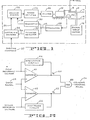
- a disc drive comprises a pair of magnetically coated recording discs 10 and 12, each having a multiplicity of concentrically disposed recording tracks on at least one surface and being mounted on a shaft 14 which is driven by a rotary drive motor 16.
- Magnetic read/write heads 18 and 20 are operatively associated with discs 10 and 12 respectively.
- a carriage 22 on which the heads are mounted is moved radially across the discs by actuator 24 to position the heads adjacent to particular data tracks.
- Disc 12 has prerecorded thereon patterns of information in concentric rings which are used exclusively in connection with positioning apparatus to accurately position head 18 over a desired cylinder of information, and is referred to in the art as a servo data disc.
- Head 20 is also referred in the art as servo data head.
- Actuator 24 is energized by power amplifier 26 to move and stop carriage 22 and consequently heads 18 and 20 in unison at any track on the disc surfaces.
- Disc 12 and head 20 function as part of a servo mechanism for controlling the position of head 18 relative to disc 10 on which data is to be read or recorded.
- a typical disc drive usually comprises a plurality of data discs (10) and associated heads (18), arranged in a stack on shaft 14 such that corresponding data tracks of all the data discs are disposed one above the other in cylindrical fashion.
- servo data de ⁇ tected by head 20 is applied to a demodulator 28.
- Demodulator 28 produces a waveform which varies from a minimum value to a maximum value as head 20 passes over each of the concentric servo data tracks on disc 12. Consequently the waveform produced by demodulator 28 is representative of linear displacement of the head carriage 22, and is applied to a tachometer 30 and cylinder detector 32.
- Cylinder detector 32 produces a single pulse for each track or cylinder of servo data which head 20 crosses on servo disc 12 as head carriage 22 moves heads 18 and 20 radially across the surfaces of discs 10 and 12.
- the pulses so produced by cylinder detector 32 are supplied to difference counter 34 which keeps track of the exact instantaneous location of heads 18 and 20 relative to the cylinders of recorded information on disc 10 and 12 by counting the number of cylinder crossings detected by head 20 as it moves across servo data disc 12.
- Difference counter 34 also receives position command 37 from an external control system which indicates the desired cylinder over which head 18 is to be positioned for the recording or playback of information. Difference counter 34 thereafter supplies the necessary signal to an actuator control 36 for the subsequent repositioning of head carriage 22. Actuator control 36 also receives a signal from tachometer 30 which indicates the relative speed and direction at which head carriage 22 and consequently heads 18 and 20 are currently moving. Based on signals 31 and 35 supplied from tachometer 30 and difference counter 34, respectively, actuator control 36 generates the necessary command signal for power amplifier 26 to drive actuator 24 to position head 18 over the desired-cylinder on disc 10 in the minimum amount of time.
- the ideal waveform produced by demodulator 28 in response to movement of head 20 over servo data tracks on disc 12 will vary between maximum and minimum values in response to said movement.
- the maximum value attained by the waveform occurs when servo head 20 is in direct alignment with a servo data track on disc 12, and the minimum value occurs when servo head 20 is midway between two adjacent servo data tracks.
- Cylinder detector circuit 32 function to count each cycle of the waveform generated by demodulator 28 and generate a pulse each time the waveform crosses zero. This has frequently been done by employing circuits whose outputs change state when the value of the input signal thereto exceeds a given predetermined value. In order to minimize the effects of noise on the input signal thereto, these circuits are designed such that the point on the input waveform at which a change in state occurs depends upon the current state of the circuit. A circuit exhibiting such a characteristic is said to employ hysteresis.
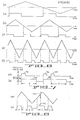
- FIGURE 2 illustrates a typical circuit employed in the prior art to detect cylinder crossings and is composed of two comparators 40 and 42 with associated hysteresis circuits 44 and 46.
- the outputs of comparators 40 and 42, V and V B are connected to AND gate 48 the, output of which forms a cylinder crossing pulse 56.
- Each hysteresis circuit has associated therewith predefined levels with reference to the input waveform at which the circuit will change states. These are illustrated with reference to an assumed input waveform from demodulator 28 in FIGURE 3(a).
- the levels associated with comparator 40 and hysteresis circuit 44 are B and C (FIGURE 3(a)), and the levels associated with comparator 42 and hysteresis circuit 46 are A and B.
- An output 29 from demodulator 28 (FIGURE 1) serves as the input to cylinder detector 32, and is hereinafter referred to as input signal 29 (FIGURE 2).
- hysteresis The difference in switching levels B and C, i.e., the first change from a low state to a high state at level B, and the subsequent switching back to the previous low state at a level different from B, i.e., C, of comparator 40 and hysteresis circuit 44 is referred to as hysteresis.
- the purpose of the hysteresis present in the cylinder detector circuit i.e., the difference in switching levels, can best be understood by considering the response of the circuit of FIGURE 2 to the presence of extraneous noise on input signal 29, as illustrated by discontinuities 64 and 66 on the waveform illustrated in FIGURE 3(a).
- discontinuity 64 by the circuit of FIGURE 2 it will be observed that when input signal 29 exceeds level B, the output V A changes from a low to a high state.
- discontinuity 64 has no effect on cylinder crossing pulse 56. This results from the fact that the amplitude of the discontinuity experienced on input signal 29 fell within the hysteresis levels associated with comparator 40. However this may not always be the case, as illustrated by discontinuity 66 in FIGURE 2(a).
- discontinuity 66 In considering the-effect of discontinuity 66 on the output of the circuit of FIGURE 2, it will be observed that the level of discontinuity 66 exceeds the hysteresis levels A and B of comparator 42, and consequently results in the output signal V B switching in response thereto. This results in the generation of an extraneous pulse 68 from the output of AND gate 48. In actual practice, such an occurrence would result in an error in the number of cylinders counted, and a corresponding error in the detected location of the heads relative to the discs.
- the input signal 29 from demodulator 28 (FIGURE 1) seldom approaches the ideal shape indicated in FIGURE 3(a) in actual practice. Rather the signal suffers from a number of short comings hereinafter discussed which directly effect the amplitude thereof. When considered in view of the techniques previously employed in detecting cylinder crossings, these short comings frequently result in incorrect counts of cylinder crossings.
- the normal peak amplitude of the output from demodulator 28 is rounded off before reaching the ideal peak amplitude. This is illustrated in FIGURE 4.
- the resulting normal peak amplitude 72 frequently varies from a minimum value shown at 74 to a maximum value shown at 76.
- the average value of peak amplitude 72 is frequently approximately 75% of the ideal peak amplitude 70. This results in a corresponding reduction of the maximum amount of useable hysteresis in the cylinder detection circuit, and consequently limits the safety margins for noise protection.
- immunity from ab - solute and peak amplitude variations on the signal from demodulator 28 is achieved by an approach which can best be understood by reference to FIGURE 5.
- input signal 29 is simultaneously applied to a reference crossing detector 80 and a velocity level detection circuit 82.
- reference crossing detector 80 produces an indication 86 thereof which triggers the generation of a single pulse 88 by pulse generation circuit 84.
- the width of the pulse produced by pulse generation circuit 84 is determined by the relative velocity of the heads 18 and 20 with respect to the surface of discs 10 and 12 (FIGURE l), as determined by the output 90 of the velocity level detection circuit 82.
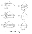
- FIGURES 6(a), 6(c) and 6(e) illustrate the waveform present on input signal 29 at progressively increasing velocities of heads 18 and 20 with respect to disc 10 and 12 (FIGURE 1). It is observed that the period of the waveform decreases as the velocity increases.
- FIGURES 6(b), 6(d) and 6(f) illustrate the corresponding pulses produced by the pulse generation circuit 89 of the present invention in response thereto.
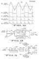
- Pulse generation circuit 84 (FIGURE 5) produces a single output pulse 88 in response to a "trigger" pulse applied to the input 86 thereto.
- the particular characteristic of pulse generation circuit 84 of interest herein is that once the production of an output pulse 88 has been initiated by the occurrence of a trigger pulse 86 on the input thereto, the subsequent occurrence of an additional trigger pulse on the input, prior to the completion of the output pulse produced in response to the initial trigger pulse, will not result in the production of an addition output pulse. To the contrary, the only effect on the output pulse currently in progress will be that the timing of the period thereof will begin anew. This is illustrated in FIGURE 7.
- the occurrence of pulse 92 on input 86 of pulse generation circuit 84 results in the generation of output pulse 94 (FIGURE 7(b)) having a duration of t.
- the occurrence of pulse 96 on input 86 will result in the generation of output pulse 98.
- the occurrence of a subsequent pulse 100 on input 86 prior to the completion of the output pulse initiated by pulse 96 results in the extension of the period of output pulse 98 by a time period t.
- FIGURE 8(a) illustrates the waveform of input signal 29 with the presence of noise pulse 101.
- FIGURE 8(b) illustrates the response of a cylinder crossing detection circuit employing the present invention. It is observed that an output pulse is produced for each crossing of the waveform illustrated in FIGURE 8(a), having a duration of t. However, upon the occurrence of noise pulse 101, it is observed that an additional output pulse in response thereto does not occur; to the contrary, the only net effect of the occurrence of noise pulse 101 is the lengthening of pulse 102 by a period equal to t.
- FIGURE 9 illustrates a preferred embodiment of the reference crossing detector 80 (FIGURE 5).
- Input signal 29 is applied to the non-inverting input of comparator 103, the inverting input thereto being referenced to ground.
- the output 102 of comparator 103 is then simultaneously applied to a positive edge trigger single shot 104 and to a negative edge trigger single shot 106.
- the outputs 108 and 110 of positive edge trigger single shot 104 and negative edge trigger single shot 106, respectively, are each applied to the inputs of OR gate l12 which in turn, produces output 86.
- FIGURE 10 illustrates the waveforms associated with the preferred embodiment of the reference crossing detector illustrated in FIGURE 9: input signal 29 (FIGURE 10(a)), output 102 of comparator 103 (FIGURE 10(b)), and outputs 108 (FIGURE 10(c)), 110 (FIGURE 10(d)) and 86 (FIGURE 10(e)), of positive edge trigger single shot 104, negative edge trigger single shot 106, and OR gate 112, respectively.
- Comparator 103 functions to compare input signal 29 (FIGURE 10(a)) with a reference level, which in the implementation shown in FIGURE 9 is zero volts, and produces an output signal 102 (FIGURE 10(b)) which is a constant positive value when input signal 29 is greater than zero volts and is a constant negative value when input signal 29 is less than zero volts.
- Positive edge trigger single shot 104 produces an output pulse on output signal 108 (FIGURE 10(c)) of fixed duration upon each transition of the output signal 102 of comparator 103 from a low to a high level, i.e., every time input signal 29 crosses the zero volt level with a positive slope.
- Negative edge trigger single shot 106 produces an output pulse on output signal 110 (FIGURE 10(d)) of fixed duration upon each transition of the output 102 of comparator 103 from a high to a low level, i.e., every time input signal 29 crosses the zero volt level with a negative slope.
- the output signal 86 (FIGURE 10(e)) from OR gate 112 is consequently a pulse upon every crossing of input signal 29 across the zero volt reference level.
- FIGURE 11 illustrates a preferred embodiment of the velocity level detection circuit 82 (FIGURE 5).
- Input signal 29 is applied as an input to a positive absolute differentiator 120 which functions to perform the mathematical operation of differentiation upon the input signal 29 and then converts the result into positive absolute value.
- As input signal 29 represents relative position of heads 18 and 20 with respect to cylinders of data . on discs 10 and 12 (FIGURE 1), the differentiation thereof produces a signal 122 which is representative of the velocity thereof.
- This signal is then applied to filter 124 which functions to remove the high frequency components therefrom.
- the resulting signal 126 from filter 124 is simultaneously applied to the inverting inputs of comparators 128 and 130.
- a third reference voltage 132 is applied to the non-inverting input of comparator 128, and represents a velocity level A against which signal 126 will be compared.
- the output 136 from comparator 128 consequently will assume a first state when the input velocity signal 126 is less than reference velocity A represented by third reference voltage 132, and will assume a second state when the input velocity signal 126 is greater than reference velocity A representated by third reference voltage 132.
- Comparator 130 functions in a like manner, the only difference being in the reference velocity level against which signal 126 will be compared.
- Fourth reference voltage 134 represents this second velocity level B.
- FIGURE 12(a) represents the output signal 126 after filtering by filter 124 from positive absolute differentiator 120, and consequently the velocity of heads 18 and 20 with respect to discs 10 and 12 (FIGURE 1).
- FIGURE 12(b) represents the output signal 126 after filtering by filter 124 from positive absolute differentiator 120, and consequently the velocity of heads 18 and 20 with respect to discs 10 and 12 (FIGURE 1).
- FIGURE 12(c) illustrates the velocity ranges indicated by the respective states of the output signals velocity level A and velocity level B produced by comparators 128 and 130 respectively.
- output signals A and B represent output signal 90 from velocity level detection circuit 82 (FIGURE 5).
- FIGURE 13 illustrates a preferred embodiment of the pulse generation circuit 84 illustrated in FIGURE 5.
- the output signals A and B from comparators 128 and 130 (FIGURE 11) are applied to the D inputs of D -type flip-flops 150 and 152.
- the binary state of these two signals are clocked into the flip-flops 150 and 152 by the clock signal 178 being supplied to the clock inputs 156 and 158 thereto.
- This serves to store the current binary status of these two signals which is representative of the velocity range at which the heads 18 and 20 are moving relative to discs 10 and 12 (FIGURE 1).
- Decoder 160 functions to decode the binary status of the-velocity information stored in flip-flops 150 and 152.
- decoder 160 can be further understood by reference to FIGURE 14 which illustrates the binary outputs El, E2, E3 and E U 166 from decoder 160 for each of the possible'binary input states, and the corresponding velocity ranges indicated thereby. It is clear that the particular output of decoder 160 which exists in the high state at any one time is representative of the velocity range at which heads 18 and 20 are currently moving with respect to discs 10 and 12 (FIGURE 1).
- the outputs El, E2 and E3 from decoder 160 are respectively applied to the RESET inputs of single shots 170, 172 and 174.
- Single shots 170, 172 and 174 each function in the following manner.
- Each single shot upon the application of a low-to-high transition on its respective clock CK input, will generate an output pulse in response thereto of a fixed duration.
- the precise period of the respective output pulse is determined by individual parameters associated with each of the individual single shots, the determination of the period of which will be hereinafter discussed.
- application of a LOW level signal to the respective RESET input of a single shot will inhibit the generation of an output pulse in response to a triggering input applied thereto.
- Each of the outputs from single shots 170, 172 and 174 are applied to the inputs of NOR gate 176.
- the output 178 from NOR gate,176 consequently is a single pulse generated upon each zero crossing of the output waveform from demodulator 28 (FIGURE 1), the width of which is determined by the relative velocity of heads 18 and 20 with respect to discs 10 and 12. It should be noted that the output 178 from NOR gate 176 is active in the low state, i.e., NOR gate 176 provides a logical inversion of the pulses 171, 173 and 175 supplied as an input thereto.
- the output 178 from NOR gate 176 is supplied to the clock CK inputs of D-type flip-flops 150 and 152 to clock in the current binary state representative of velocity.
- the output 178 from NOR gate 176 is supplied to the clock CK inputs of D-type flip-flops 150 and 152 to clock in the current binary state representative of velocity.
- FIGURE 15(a) represents a typical output waveform 29 from demodulator 28 (FIGURE 1).
- FIGURE 15(b) illustrates the corresponding signal 86 (FIGURE 10(e)) produced by the implementation of reference crossing detector 80 (FIGURE 5).
- FIGURE 15(c) illustrates the resulting cylinder crossing pulses 178 (FIGURE 13) produced in response thereto by the present invention for a single velocity range. It is observed from FIGURE 15(b) that pulses 180, 182 and 184 represent extraneous pulses produced by noise 179, 181 and 183 present on the waveform illustrated in FIGURE 15(a). When such pulses are applied to single shots 170, 172 and 174 (FIGURE 13) each would result in the retrig- gering of the selected single shot, rather than the production of an additional cylinder crossing pulse.
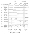
- FIGURE 16 illustrates waveforms associated with the operation of the circuit implementation illustrated in FIGURE 13.
- the zero crossing pulse 86 waveform present on the CK input to single shots 170, 172 and 174 is illustrated in FIGURE 16(a), as are the velocity level A and velocity level B waveforms present on the D inputs to flip-flops 150 and 152 illustrated in FIGURES 16(b) and 16(c) respectively.
- the corresponding output waveforms El, E2 and E3 from decoder 160 are illustrated in FIGURES 16(d), 16(e) and 16(f) respectively.
- the output waveforms 171, 173 and 175 from single shots 170, 172 and 174 are illustrated in FIGURES 16(g), 16(h) and 16(k).
- the resulting output 178 from NOR gate 176 is illustrated in FIGURE 16(m).
- decoder 160 output El (FIGURE 16(d)) is in a high state, which enables single shot 170 to produce an output pulse 191 (FIGURE 16(g)) of a duration t l previously defined by parameters associated with single shot 170.
- a corresponding cylinder crossing pulse 192 of duration t 1 (FIGURE 16(m)) is produced.
- decoder 160 output El will remain in a high state which, upon the occurrence of pulse 196 (FIGURE 16(a)) will result in a single shot 170 again producing an output pulse 197 (FIGURE 16(g)) which in turn produces cylinder crossing pulse 198 (FIGURE 16(m)).
- single shot 172 Upon the occurrence of pulse 200 (FIGURE 16(a)), single shot 172 will be enabled due to decoder 160 output E2 being in a high state, and will produce an output pulse 201 (FIGURE 16(h)) in response thereto on output 173 having a duration of t 2 .
- This pulse is reflected in the output from NOR gate 176 as pulse 202.
- pulse 202 was produced by the triggering of single shot 172 (FIGURE 13) during a period when the velocity of heads 18 and 20 with respect to disc 10 and 12 (FIGURE 1) had changed from RANGE 1 to RANGE 2, the corresponding output pulse produced thereby will be shorter in duration than the pulse previously produced when the velocity of said heads was within RANGE 1. This can be observed by comparing the respective widths of pulse 202 with that of pulse 198 (FIGURE 16(m)).
- circuit of FIGURE 13 will respond to the occurrence of zero crossing pulses when the velocity of the heads is within the range defined by RANGE 3, hence enabling decoder 160 output E3 and single shot 174, in a similar fashion.
- any number of velocity ranges may be defined, the choice being dependent upon particular considerations present in the application of the present invention.
- FIGURE 17(a) illustrates a half cycle of an assumed input waveform having a basic triangular shape, and a half cycle period of 1000 microseconds. This represents the assumed lowest velocity of the corresponding transducer producing same. Assuming the pulse to be produced by the respective single shot to occupy 20% of this period, and consequently to reflect approximately 40% of the positive slope of the input waveform after crossing the zero reference level, a period of 200 microseconds results (20% of 1000 microseconds).
- a cylinder crossing detector is only illustrature of one approach.
- the duration of the pulse indicating a cylinder crossing could vary in direct proportion to the measured velocity of the moveable head assembly, rather than in one or a plurality of discrete ranges.
Landscapes
- Moving Of Head For Track Selection And Changing (AREA)
- Transmission And Conversion Of Sensor Element Output (AREA)
- Control Of Position Or Direction (AREA)
- Signal Processing For Digital Recording And Reproducing (AREA)
Applications Claiming Priority (2)
| Application Number | Priority Date | Filing Date | Title |
|---|---|---|---|
| US06/418,492 US4516178A (en) | 1982-09-15 | 1982-09-15 | Cylinder crossing detection circuit for disc drive or the like |
| US418492 | 1982-09-15 |
Publications (2)
| Publication Number | Publication Date |
|---|---|
| EP0103492A1 true EP0103492A1 (de) | 1984-03-21 |
| EP0103492B1 EP0103492B1 (de) | 1987-12-02 |
Family
ID=23658336
Family Applications (1)
| Application Number | Title | Priority Date | Filing Date |
|---|---|---|---|
| EP83305402A Expired EP0103492B1 (de) | 1982-09-15 | 1983-09-15 | Detektor für Zylinderüberkreuzungen für Plattenantriebe |
Country Status (4)
| Country | Link |
|---|---|
| US (1) | US4516178A (de) |
| EP (1) | EP0103492B1 (de) |
| JP (1) | JPS5972684A (de) |
| DE (1) | DE3374820D1 (de) |
Families Citing this family (13)
| Publication number | Priority date | Publication date | Assignee | Title |
|---|---|---|---|---|
| US4638383A (en) * | 1984-02-22 | 1987-01-20 | Mcginlay James G | Micro hard-disk drive system |
| FR2568076B1 (fr) * | 1984-07-18 | 1986-11-21 | Onera (Off Nat Aerospatiale) | Dispositif hybride d'analyse multiplex d'image. |
| JPS6149518A (ja) * | 1984-08-17 | 1986-03-11 | Fuji Photo Film Co Ltd | ゼロクロスポイントの検出回路 |
| JPS6252771A (ja) * | 1985-08-30 | 1987-03-07 | Toshiba Corp | 磁気ヘツドの速度検出装置 |
| EP0220812A3 (de) * | 1985-09-06 | 1988-11-09 | Rodime PLC | Plattengerät mit hoher Kapazität |
| JPS6352307A (ja) * | 1986-08-20 | 1988-03-05 | Toshiba Corp | 磁気デイスク装置 |
| US4878136A (en) * | 1988-09-14 | 1989-10-31 | Miniscribe Corporation | Track crossing detector |
| JP2684772B2 (ja) * | 1989-06-01 | 1997-12-03 | ソニー株式会社 | アクチュエータの駆動回路 |
| US5402054A (en) * | 1989-09-11 | 1995-03-28 | Boral Johns Perry Industries Pty. Ltd. | Variable speed AC drive control |
| JPH05205416A (ja) * | 1991-10-18 | 1993-08-13 | Internatl Business Mach Corp <Ibm> | 媒体欠陥によるトラッキング・エラー信号異常のマスキング装置および方法 |
| US5581169A (en) * | 1994-08-31 | 1996-12-03 | Allen-Bradley Company, Inc. | Apparatus used with an inverter/converter eliminating unintended voltage pulses |
| JP3683155B2 (ja) * | 2000-03-08 | 2005-08-17 | 富士通株式会社 | ディスク装置のヘッド位置決め制御方法及び装置 |
| DE10228035B4 (de) * | 2002-04-19 | 2016-10-27 | Continental Teves Ag & Co. Ohg | Einrichtung zur Ermittlung der Nulldurchgänge |
Citations (5)
| Publication number | Priority date | Publication date | Assignee | Title |
|---|---|---|---|---|
| US4149200A (en) * | 1977-10-31 | 1979-04-10 | Burroughs Corporation | Transducer positioning system |
| GB2015204A (en) * | 1978-02-28 | 1979-09-05 | Digital Equipment Corp | Transducer positioning system for rotating disc drive units |
| EP0007449A1 (de) * | 1978-07-31 | 1980-02-06 | Siemens Aktiengesellschaft | Verfahren zum Erzeugen von digitalen Ist-Geschwindigkeitssignalen in einem Positioniersystem für die Schreib-/Leseköpfe eines Magnetplattenspeichers |
| EP0010664A1 (de) * | 1978-10-27 | 1980-05-14 | International Business Machines Corporation | Verfahren und Anordnung zur Lageregelung eines Abtastkopfes |
| EP0013326A2 (de) * | 1978-12-27 | 1980-07-23 | International Business Machines Corporation | Servo-Lageregelungssystem mit abgetasteten Positionswerten und seine Anwendung in einem Plattenspeicher mit Servo-Sektoren |
Family Cites Families (7)
| Publication number | Priority date | Publication date | Assignee | Title |
|---|---|---|---|---|
| US3597750A (en) * | 1969-01-21 | 1971-08-03 | Information Storage Systems | Servo with agc for positioning a magnetic head |
| US3755795A (en) * | 1971-08-23 | 1973-08-28 | Information Storage Systems | Arrival detection and data transfer control system for data |
| JPS5373121A (en) * | 1976-12-13 | 1978-06-29 | Fujitsu Ltd | Cylindrical pulse generating circuit |
| JPS541005A (en) * | 1977-06-03 | 1979-01-06 | Nec Corp | Locating controller |
| JPS5564661A (en) * | 1978-11-08 | 1980-05-15 | Toshiba Corp | Self-compensator for magnetic disk memory unit |
| US4381526A (en) * | 1980-11-10 | 1983-04-26 | Memorex Corporation | Velocity control system for a data storage apparatus |
| JPS57147167A (en) * | 1981-03-06 | 1982-09-10 | Nec Corp | Gain controlling system for head positioner for disc device |
-
1982
- 1982-09-15 US US06/418,492 patent/US4516178A/en not_active Expired - Lifetime
-
1983
- 1983-09-15 EP EP83305402A patent/EP0103492B1/de not_active Expired
- 1983-09-15 DE DE8383305402T patent/DE3374820D1/de not_active Expired
- 1983-09-16 JP JP58171047A patent/JPS5972684A/ja active Pending
Patent Citations (5)
| Publication number | Priority date | Publication date | Assignee | Title |
|---|---|---|---|---|
| US4149200A (en) * | 1977-10-31 | 1979-04-10 | Burroughs Corporation | Transducer positioning system |
| GB2015204A (en) * | 1978-02-28 | 1979-09-05 | Digital Equipment Corp | Transducer positioning system for rotating disc drive units |
| EP0007449A1 (de) * | 1978-07-31 | 1980-02-06 | Siemens Aktiengesellschaft | Verfahren zum Erzeugen von digitalen Ist-Geschwindigkeitssignalen in einem Positioniersystem für die Schreib-/Leseköpfe eines Magnetplattenspeichers |
| EP0010664A1 (de) * | 1978-10-27 | 1980-05-14 | International Business Machines Corporation | Verfahren und Anordnung zur Lageregelung eines Abtastkopfes |
| EP0013326A2 (de) * | 1978-12-27 | 1980-07-23 | International Business Machines Corporation | Servo-Lageregelungssystem mit abgetasteten Positionswerten und seine Anwendung in einem Plattenspeicher mit Servo-Sektoren |
Also Published As
| Publication number | Publication date |
|---|---|
| JPS5972684A (ja) | 1984-04-24 |
| DE3374820D1 (en) | 1988-01-14 |
| EP0103492B1 (de) | 1987-12-02 |
| US4516178A (en) | 1985-05-07 |
Similar Documents
| Publication | Publication Date | Title |
|---|---|---|
| US4454549A (en) | Slant track sector servo | |
| CA1079846A (en) | Record track following and seeking | |
| US4101942A (en) | Track following servo system and track following code | |
| US4238809A (en) | Servo track configuration for magnetic disk apparatus | |
| US4912576A (en) | Method for writing a servo pattern | |
| US4006394A (en) | Coarse and fine control for position servo | |
| EP0207692B1 (de) | Servosteuersystem zur Zentrierung eines Wandlerkopfes auf einer Datenspur einer magnetischen Platte | |
| EP0094314B2 (de) | Positioniersteuerungssystem mit sowohl kontinuierlichen als auch eingefügten Servoinformationen für einen Magnetplattenspeicher | |
| US4390912A (en) | Transducer positioning system and data disk therefor | |
| US4516178A (en) | Cylinder crossing detection circuit for disc drive or the like | |
| CA1124389A (en) | Transducer positioning system for rotating disk drive units | |
| US5233486A (en) | Method for correcting track counting errors during seeks in a hard disc drive | |
| US4354208A (en) | Magnetic recording medium and digital storage device including same | |
| US4285015A (en) | Method and apparatus for locating a movable servo controlled member during position signal drop-out | |
| CA1196099A (en) | Device for rapidly moving an optical pick-up device in an optical reproducing apparatus to a desired position on a record disc | |
| US4685007A (en) | Disk drive with track zero location system | |
| JPS63140469A (ja) | デイスク記憶装置の基準トラツク検出方式 | |
| US5115359A (en) | Fault tolerant frame, guardband and index detection methods | |
| US6034829A (en) | Disk drive and servo pattern write method for preventing read errors resulting from a thermal asperity within an erase area between a servo pad area and a gray code area | |
| US5305157A (en) | Read circuit providing two different reference levels for reading the servo sectors and data sectors of a rotating data storage disk | |
| US5247398A (en) | Automatic correction of position demodulator offsets | |
| US5973869A (en) | Servo frame edge detection for tape servo pattern with synchronization field | |
| US4556921A (en) | Method and apparatus to improve the positioning accuracy of a tracking arm | |
| US4519007A (en) | Servo-track position detection systems | |
| EP0082645A1 (de) | Lagemesssysteme mit Servospur |
Legal Events
| Date | Code | Title | Description |
|---|---|---|---|
| PUAI | Public reference made under article 153(3) epc to a published international application that has entered the european phase |
Free format text: ORIGINAL CODE: 0009012 |
|
| AK | Designated contracting states |
Designated state(s): DE FR GB IT NL SE |
|
| 17P | Request for examination filed |
Effective date: 19840908 |
|
| 17Q | First examination report despatched |
Effective date: 19860117 |
|
| ITF | It: translation for a ep patent filed | ||
| GRAA | (expected) grant |
Free format text: ORIGINAL CODE: 0009210 |
|
| AK | Designated contracting states |
Kind code of ref document: B1 Designated state(s): DE FR GB IT NL SE |
|
| REF | Corresponds to: |
Ref document number: 3374820 Country of ref document: DE Date of ref document: 19880114 |
|
| ET | Fr: translation filed | ||
| PLBE | No opposition filed within time limit |
Free format text: ORIGINAL CODE: 0009261 |
|
| STAA | Information on the status of an ep patent application or granted ep patent |
Free format text: STATUS: NO OPPOSITION FILED WITHIN TIME LIMIT |
|
| 26N | No opposition filed | ||
| PGFP | Annual fee paid to national office [announced via postgrant information from national office to epo] |
Ref country code: GB Payment date: 19900803 Year of fee payment: 8 |
|
| PGFP | Annual fee paid to national office [announced via postgrant information from national office to epo] |
Ref country code: FR Payment date: 19900919 Year of fee payment: 8 |
|
| PGFP | Annual fee paid to national office [announced via postgrant information from national office to epo] |
Ref country code: SE Payment date: 19900921 Year of fee payment: 8 |
|
| ITTA | It: last paid annual fee | ||
| PGFP | Annual fee paid to national office [announced via postgrant information from national office to epo] |
Ref country code: NL Payment date: 19900930 Year of fee payment: 8 |
|
| PGFP | Annual fee paid to national office [announced via postgrant information from national office to epo] |
Ref country code: DE Payment date: 19901031 Year of fee payment: 8 |
|
| PG25 | Lapsed in a contracting state [announced via postgrant information from national office to epo] |
Ref country code: GB Effective date: 19910915 |
|
| PG25 | Lapsed in a contracting state [announced via postgrant information from national office to epo] |
Ref country code: SE Effective date: 19910916 |
|
| PG25 | Lapsed in a contracting state [announced via postgrant information from national office to epo] |
Ref country code: NL Effective date: 19920401 |
|
| GBPC | Gb: european patent ceased through non-payment of renewal fee | ||
| NLV4 | Nl: lapsed or anulled due to non-payment of the annual fee | ||
| PG25 | Lapsed in a contracting state [announced via postgrant information from national office to epo] |
Ref country code: FR Effective date: 19920529 |
|
| PG25 | Lapsed in a contracting state [announced via postgrant information from national office to epo] |
Ref country code: DE Effective date: 19920602 |
|
| REG | Reference to a national code |
Ref country code: FR Ref legal event code: ST |
|
| EUG | Se: european patent has lapsed |
Ref document number: 83305402.6 Effective date: 19920408 |