EP0103484A2 - Machine de remplissage de liquides mousseux - Google Patents
Machine de remplissage de liquides mousseux Download PDFInfo
- Publication number
- EP0103484A2 EP0103484A2 EP83305347A EP83305347A EP0103484A2 EP 0103484 A2 EP0103484 A2 EP 0103484A2 EP 83305347 A EP83305347 A EP 83305347A EP 83305347 A EP83305347 A EP 83305347A EP 0103484 A2 EP0103484 A2 EP 0103484A2
- Authority
- EP
- European Patent Office
- Prior art keywords
- container
- fill
- sleeve
- tip
- liquid
- Prior art date
- Legal status (The legal status is an assumption and is not a legal conclusion. Google has not performed a legal analysis and makes no representation as to the accuracy of the status listed.)
- Withdrawn
Links
Images
Classifications
-
- B—PERFORMING OPERATIONS; TRANSPORTING
- B67—OPENING, CLOSING OR CLEANING BOTTLES, JARS OR SIMILAR CONTAINERS; LIQUID HANDLING
- B67C—CLEANING, FILLING WITH LIQUIDS OR SEMILIQUIDS, OR EMPTYING, OF BOTTLES, JARS, CANS, CASKS, BARRELS, OR SIMILAR CONTAINERS, NOT OTHERWISE PROVIDED FOR; FUNNELS
- B67C3/00—Bottling liquids or semiliquids; Filling jars or cans with liquids or semiliquids using bottling or like apparatus; Filling casks or barrels with liquids or semiliquids
- B67C3/02—Bottling liquids or semiliquids; Filling jars or cans with liquids or semiliquids using bottling or like apparatus
- B67C3/22—Details
- B67C3/26—Filling-heads; Means for engaging filling-heads with bottle necks
- B67C3/2608—Filling-heads; Means for engaging filling-heads with bottle necks comprising anti-dripping means
-
- B—PERFORMING OPERATIONS; TRANSPORTING
- B67—OPENING, CLOSING OR CLEANING BOTTLES, JARS OR SIMILAR CONTAINERS; LIQUID HANDLING
- B67C—CLEANING, FILLING WITH LIQUIDS OR SEMILIQUIDS, OR EMPTYING, OF BOTTLES, JARS, CANS, CASKS, BARRELS, OR SIMILAR CONTAINERS, NOT OTHERWISE PROVIDED FOR; FUNNELS
- B67C3/00—Bottling liquids or semiliquids; Filling jars or cans with liquids or semiliquids using bottling or like apparatus; Filling casks or barrels with liquids or semiliquids
- B67C3/02—Bottling liquids or semiliquids; Filling jars or cans with liquids or semiliquids using bottling or like apparatus
- B67C3/04—Bottling liquids or semiliquids; Filling jars or cans with liquids or semiliquids using bottling or like apparatus without applying pressure
-
- B—PERFORMING OPERATIONS; TRANSPORTING
- B67—OPENING, CLOSING OR CLEANING BOTTLES, JARS OR SIMILAR CONTAINERS; LIQUID HANDLING
- B67C—CLEANING, FILLING WITH LIQUIDS OR SEMILIQUIDS, OR EMPTYING, OF BOTTLES, JARS, CANS, CASKS, BARRELS, OR SIMILAR CONTAINERS, NOT OTHERWISE PROVIDED FOR; FUNNELS
- B67C3/00—Bottling liquids or semiliquids; Filling jars or cans with liquids or semiliquids using bottling or like apparatus; Filling casks or barrels with liquids or semiliquids
- B67C3/02—Bottling liquids or semiliquids; Filling jars or cans with liquids or semiliquids using bottling or like apparatus
- B67C3/22—Details
- B67C3/26—Filling-heads; Means for engaging filling-heads with bottle necks
- B67C2003/2671—Means for preventing foaming of the liquid
Definitions
- the present invention relates to filling of containers, such as bottles, with flowable substances and is particularly directed to thin liquids which readily form suds or foam.
- the present invention is directed to a machine with these features.
- the machine includes a container filling section having a rotating platform on which containers are supported as they are filled.
- the machine also includes an infeed section for feeding empty containers onto the rotating platform.
- the infeed section is equipped with an infeed star assembly capable of receiving and holding empty containers and discharging the empty containers onto the rotating platform.
- the infeed star assembly includes at least one container star mounted on a propelling axis.
- the machine also includes filling means comprising a plurality of filling nozzle assemblies and means for inserting a filler nozzle into an empty container held by the infeed star assembly.
- the filling nozzle assembly comprises as a nozzle an elongated hollow fill sleeve or tube and a fill tip at the first or fill end of the sleeve.
- the fill end of the sleeve is inserted into a container.
- the fill tip is axially slideable relative to the sleeve for opening and closing the fill end of the sleeve.
- the sleeve is biased relative to the fill tip to a closed position.
- the machine also includes means for lowering the sleeve tube and tip into the container and means for raising the sleeve and tip from the container.
- a preventing means such as a collar mounted on the sleeve prevents the sleeve from reaching the bottom of the container as the sleeve and tip approach the bottom of the container.
- the tip and sleeve are axially displaced relative to each other. This opens the fill end of the sleeve against the force of the biasing means.
- Latch means are provided for maintaining the fill end of the sleeve open as the sleeve and tip are raised from the bottom to the top of the container. Means are provided for releasing the latch means when the sleeve is raised almost to the top of the container by the raising means.
- the fill sleeve is lowered to a position almost to the bottom of the container.
- Liquid is continuously introduced into the container through the fill sleeve while simultaneously raising the fill sleeve and tip toward the top of the container so that the bottom of the fill sleeve is below the level of the top of the liquid in the container.
- the liquid is introduced into the container in a controlled volume by a metering piston. Introduction of the liquid into the container is stopped by release of the latch when the bottom of the fill sleeve is raised to a level just below the desired liquid level in the container.
- the machine preferably includes a nozzle star for holding the elongated fill sleeves as they are inserted into empty containers.
- the nozzle star is located above the container star.
- the lower surface of the fill tip is slanted downwardly toward its axial centerline and includes a vacuum port at the lowermost portion of the lower surface of the tip so that drops of liquid remaining on the tip do not drip because they are sucked up as the tip is removed from a container.
- a vacuum shroud cooperates with the tip so that vacuum is pulled at the vacuum port only when the nozzle is closed and out of the container.
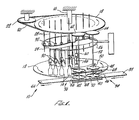
- a machine 10 includes a rotating platform or carousel 12 on which a plurality of containers such as plastic bottles 14 are carried to be filled.
- the platform 12 rotates on a central vertical axle 16 which is driven by a main sprocket 18 positioned above the platform 12.
- the main sprocket 18 is driven by a belt 20 powered by a drive gear 22.
- a cam 24 is positioned between the main sprocket 18 and the platform 12. The cam is supported by a support ring 26.
- a plurality of support rods 28 extend downwardly through the main sprocket 18 and are vertically slideable relative thereto. From each slideable support rod 28 there depends a nozzle assembly 30, there being at least as many nozzle assemblies'30 as there are containers 14 on the platform 12. Each support rod 28 has a cam follower 32 mounted thereon.
- the machine 10 includes an infeed section 34 and an outfeed section 36.
- empty containers are taken from a feed belt 38, and delivered by an infeed star assembly 40 onto the rotating platform 12.
- filled containers are taken by an outfeed star assembly 42 and delivered to a container withdraw belt 44. Both the feed belt 38 and the withdraw belt 44 can be table top chains.
- Fig. 1 the container feed belt 38 and container withdraw belt 44 move from a right to a left direction.
- the main sprocket 18 and platform 12 rotate in a counterclockwise direction (looking from above).
- the infeed star assembly 40 comprises three stars, a container body star 46, a container neck star 48 mounted above the body star 46, and a top nozzle star 50, all mounted on the same propelling axle 52 to rotate synchronously.
- the propelling axle 52 is driven by a infeed star sprocket 54 that is driven by the chain 20 around the main sprocket 18.
- the outfeed star assembly 42 comprises two stars, a lower container body star 56 and an upper neck star 58, both mounted on a propelling axle 60 driven by an outfeed star sprocket 68, which is driven by the chain 20 around the main sprocket 18.
- Each star comprises a plurality of arms 64 jutting out radially from the center of the star and a plurality of peripheral cavities 66 sized to receive a respective portion of a container or a nozzle.
- Each container star 46, 48, 56, and 58 cooperates with an upper guide 68 of lower guide 70 to hold the containers in a desired position.
- the nozzle star 50 cooperates with a nozzle guide 72 (see Fig. 5) to firmly hold nozzles in position as they are lowered into a container as described below.
- the guides can be provided with bearings 74 to assist the containers and nozzle assembly in moving to their desired position.
- bottles are fed from the container feed belt through the infeed star assembly 40 onto the rotating platform 12.
- a nozzle assembly 30 is inserted thereinto with the aid of the nozzle star 50.
- the container is filled with liquid as it and the nozzle assembly synchronously rotate around to the outfeed section 36, at which point the nozzle assembly is removed from the container, and the container is withdrawn from the platform 12 by the outfeed star assembly 42 and placed onto the container withdraw belt 44.
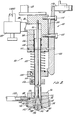
- the nozzle assembly 30 comprises four basic parts:
- the nozzle assembly 30 is supported by a horizontal mounting bar 104 that is attached to one of the sliding rods 28.
- Liquid is provided to the fill sleeve 94 in a premeasured amount from a device such as a bi-acting piston through the supply nipple 88 and lateral feed orifice 86.
- a device such as a bi-acting piston
- a throttle valve 105 is connected to the supply nipple 88 for throttling the amount of the liquid introduced so that all nozzle assemblies 30 fill at the same rate so they all complete their fill at the same point in the fill cycle.
- O-ring seals 106, 108, 116, 118, and 120, and a biasing spring 122 under compression are provided.
- the biasing spring is between the bottom of the supply body 84 and a spring split collar 124 mounted on the fill sleeve 94.
- Below the spring sleeve collar 124 is a bottle height split collar 126 mounted on the fill sleeve 94.
- the fill sleeve 94 and the rod 90 are sufficiently elongated to reach a position close to the bottom of the container to be filled.
- the fill sleeve 94 is axially, i.e. vertically, displaceable relative to the rod 90 and the tip 92.
- a vacuum line 128 is connected to the vacuum connector 98, which is in communication with a lateral vacuum vent 130 and the vacuum shroud 96.
- the radially inner surface of the vacuum shroud 96 has a vertical vent groove 132 which is in register with a cross vent hole 134 through the tip 92 when the tip is in a closed position as shown in Fig. 2.
- the tip also includes a vertical center vent hole 136 connected to the cross vent hole 134.
- the lowermost wall 138 of the tip and shroud 96 slant downwardly toward the axial centerline of the tip 92, rod 90, and fill sleeve 94, i.e., they appear to be a cone with the tip down.
- the vertical vent hole 136 terminates in a tip orifice 140 at the lowest portion of the lower wall 138 of the tip 92.
- Air vents 142 are provided along the lowermost wall of the vacuum shroud 96.
- Fluid introduced into the fill sleeve 94 is prevented from leaking therefrom into the supply body 84 by 0-rings 106 and 108, and is prevented from leaking through the vacuum shroud by 0-ring 118.
- 0- rings 116 and 120 hold the shrouds vacuum seal.
- the tip 92 is shown in its closed position in Fig. 2 with the tip 92 being biased by the spring 122 into engagement with sealing O-ring 118 mounted at the fill end 144 of the fill sleeve 94.
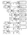
- Fig. 3A corresponds to the nozzle fill assembly in the position it is in Fig. 2, i.e. before the nozzle assembly has engaged a container 14.
- nozzle comprising the supply sleeve 94 and the tip 92 are just about to enter a container 14. Note that the nozzle is held by the nozzle star 50 and nozzle guide 72. Because of the long length of the nozzle, the nozzle star 50 is of great assistance in insuring that the nozzle goes into a container 14, expecially one with a narrow neck.
- the vacuum shroud 96 seats against the top of the container 14.
- the sleeve 94, rod 90 and tip 92 are axially slideable relative to the shroud.
- the tip 92 and the sleeve 94 move downwardly into the container 14 and continue downward movement as shown in Fig. 3D. No filling has yet occurred because the tip 92 is in tight engagement with sealing orifice 118 under the force of the biasing spring 122.
- Fig. 3E fill begins.
- the lower split collar 126 seats against the top of the vacuum shroud 96, preventing the sleeve 94 from continuing its downward movement.
- the tip 92 continues to move downwardly and is vertically displaced relative to the sleeve, thereby allowing liquid to flow into the container 14.
- no liquid enters into the container 14 until the fill tip 144 of the sleeve is proximate to the bottom of the container. This greatly reduces sudsing and foaming that would occur if the nozzle were opened at the top and lowered to the bottom.
- air vents 142 are open as the tip 92 enters the container 14, i.e., in Fig. 3C, so that air can be vented out of the container 14 as liquid is placed therein. It should also be noted that because the tip 92 is vertically displaced from the vacuum shroud 96, there is no vacuum at the tip 140 because the vent grooves 132 and the vent cross hole 134 are no longer in register. No vacuum loss occurs because of 0-rings 116 and 120. This is energy efficient, and leads to accurate fill because premeasured liquid is not sucked out of the container.
- the latch 100 catches the bottom of the spring split collar 124 as the spring 122 is compressed. This holds the fill sleeve 94 and the tip 92 axially displaced relative to each other until the latch is released so that the nozzle remains in an open position.
- the latch is held in place by a spring 110 ( Figure 2).
- nozzle is being raised from the bottom of the container toward the top of the container.
- the rate at which the nozzle is raised is sufficiently slow that the fill tip remains below the liquid level in the container to avoid foaming and sudsing.
- the latch is released by a release wheel 146 (Fig. 4) that is supported by the cam 24. This releases the tip 92 to move into the position shown in Figs. 2, 3A and 3H, thereby closing the nozzle.
- each nozzle assembly 30 varies as the nozzle assembly rotates with the main sprocket 18 due to the cam follower 32 attached to the support rod 28 following the vertical position of the top of the cam 24.
- nozzle assembly positions as shown in Figs. 3 A-H are provided.
- directly above the infeed star assembly 40 are letters A, B and C in Fig. 4 indicating that at the infeed star assembly, the nozzle assembly moves from the position shown in Fig. 3A to the position shown in Fig. 3B, and then to the position shown in Fig. 3C.
- the nozzle assembly moves from the position shown in Fig. 3G to the position shown in Fig. 3H.
- the cam 24 is provided with an adjustable cam step 148 so that the machine can be used for filling containers to different head spacings.
- the air vents 142 are sized so that the volumetric rate at which air is forced from a container is less than the volumetric rate at which a container is filled with liquid.
- the air vents can be rectangular, 1.63 mm (0.064 inch) by 3.43 mm (0.135 inch) and 25.4 mm (1 inch) long.
- This volumetric rate condition can be met because no vacuum is pulled insider the container when filling.
- flexible containers, and particularly plastic containers tend to bulge. This allows containers to be filled leaving more headroom between the top of the liquid in the container and the top of the container. The more headroom that is allowed, the faster the filling rate that can be obtained.
- the vacuum is not used for withdrawing any excess liquid from the container, which could cause an inaccuracy. It is only used to remove drops from the tip which could contaminate the machinery or the container.
- a machine according to the present invention has many advantages. It permits rapid and accurate fill of containers, even with foamy and sudsy liquids due to the use of the bottom open/top close nozzle assembly. Because of the nozzle star, the flexing elongated nozzle assembly can be used even with narrow neck containers and no dripping centering bells are needed. The anti-drip nozzle tip helps prevent fouling of machinery which can result in inaccurate fills and substantial dowmtime. Since the nozzle is almost completely withdrawn from the container before filling is complete, the volume occupied by the nozzle is minimized. This allows the containers to appear to be almost completely filled. Bottles that appear full sell better on shelves than low fills - a great marketing advantage.
- the present invention has been described in considerable detail with reference to certain preferred versions thereof, other versions are possible.
- the main sprocket 18 can be replaced with a plate having a roller chain tightly stretched around its periphery with the drive gear 22 directly engaging the chain.
- the cam 26 can be supported by vertical rods connected to an overhead frame rather than the ring 26.
- any pre-measuring device or pump can be used. Therefore, the spirit and scope of the appended claims should not necessarily be limited to the description of the preferred versions thereof.
Landscapes
- Filling Of Jars Or Cans And Processes For Cleaning And Sealing Jars (AREA)
- Basic Packing Technique (AREA)
Applications Claiming Priority (2)
| Application Number | Priority Date | Filing Date | Title |
|---|---|---|---|
| US41750582A | 1982-09-13 | 1982-09-13 | |
| US417505 | 1982-09-13 |
Publications (2)
| Publication Number | Publication Date |
|---|---|
| EP0103484A2 true EP0103484A2 (fr) | 1984-03-21 |
| EP0103484A3 EP0103484A3 (fr) | 1984-05-02 |
Family
ID=23654280
Family Applications (1)
| Application Number | Title | Priority Date | Filing Date |
|---|---|---|---|
| EP83305347A Withdrawn EP0103484A3 (fr) | 1982-09-13 | 1983-09-13 | Machine de remplissage de liquides mousseux |
Country Status (2)
| Country | Link |
|---|---|
| EP (1) | EP0103484A3 (fr) |
| JP (1) | JPS5984790A (fr) |
Cited By (8)
| Publication number | Priority date | Publication date | Assignee | Title |
|---|---|---|---|---|
| EP0166803A1 (fr) * | 1984-07-05 | 1986-01-08 | WST Maschinen- und Apparatebau GmbH | Procédé et dispositif pour le remplissage par le bas d'un récipient |
| US5001550A (en) * | 1988-11-11 | 1991-03-19 | General Electric Co. | Quadruplex encoder and decoder for EDTV system |
| EP0906888A1 (fr) * | 1997-09-18 | 1999-04-07 | SEZ Semiconductor-Equipment Zubehör für die Halbleiterfertigung AG | Dispositif pour éviter le gouttage à un orifice de distribution |
| EP2141115A1 (fr) * | 2008-07-01 | 2010-01-06 | Krones AG | Dispositif de remplissage de fluides visqueux |
| US7762430B2 (en) | 2002-12-23 | 2010-07-27 | Deutsche Sisi-Werke Gmbh & Co. Betriebs Kg | Closing element with outlet channel extending in funnel-like manner |
| CN109019487A (zh) * | 2018-09-03 | 2018-12-18 | 平顶山市绿禾农业科技开发有限公司 | 一种防溅洒杀菌剂灌装机 |
| CN111453070A (zh) * | 2020-04-09 | 2020-07-28 | 马玉春 | 一种用于药物均匀灌装的常压灌装设备 |
| WO2021053297A1 (fr) * | 2019-09-19 | 2021-03-25 | Pep Technologies | Procédé et machine pour remplir un récipient à un niveau souhaité de liquide |
Families Citing this family (1)
| Publication number | Priority date | Publication date | Assignee | Title |
|---|---|---|---|---|
| JPH0523518Y2 (fr) * | 1987-08-12 | 1993-06-16 |
Family Cites Families (1)
| Publication number | Priority date | Publication date | Assignee | Title |
|---|---|---|---|---|
| US3056436A (en) * | 1959-06-24 | 1962-10-02 | Cherry Burrell Corp | Filling head for filling machines |
-
1983
- 1983-09-13 EP EP83305347A patent/EP0103484A3/fr not_active Withdrawn
- 1983-09-13 JP JP16911983A patent/JPS5984790A/ja active Pending
Cited By (12)
| Publication number | Priority date | Publication date | Assignee | Title |
|---|---|---|---|---|
| EP0166803A1 (fr) * | 1984-07-05 | 1986-01-08 | WST Maschinen- und Apparatebau GmbH | Procédé et dispositif pour le remplissage par le bas d'un récipient |
| US5001550A (en) * | 1988-11-11 | 1991-03-19 | General Electric Co. | Quadruplex encoder and decoder for EDTV system |
| EP0906888A1 (fr) * | 1997-09-18 | 1999-04-07 | SEZ Semiconductor-Equipment Zubehör für die Halbleiterfertigung AG | Dispositif pour éviter le gouttage à un orifice de distribution |
| US6056208A (en) * | 1997-09-18 | 2000-05-02 | Sez Semiconductor-Equipment Zubehor Fur Die Halbleiterfertigung Ag | Apparatus for preventing dripping from conduit openings |
| US7762430B2 (en) | 2002-12-23 | 2010-07-27 | Deutsche Sisi-Werke Gmbh & Co. Betriebs Kg | Closing element with outlet channel extending in funnel-like manner |
| EP2141115A1 (fr) * | 2008-07-01 | 2010-01-06 | Krones AG | Dispositif de remplissage de fluides visqueux |
| US8424575B2 (en) | 2008-07-01 | 2013-04-23 | Krones Ag | Apparatus for bottling viscous media |
| CN109019487A (zh) * | 2018-09-03 | 2018-12-18 | 平顶山市绿禾农业科技开发有限公司 | 一种防溅洒杀菌剂灌装机 |
| WO2021053297A1 (fr) * | 2019-09-19 | 2021-03-25 | Pep Technologies | Procédé et machine pour remplir un récipient à un niveau souhaité de liquide |
| FR3101074A1 (fr) * | 2019-09-19 | 2021-03-26 | Pep Technologies | Procédé et machine pour remplir un récipient à un niveau souhaité de liquide |
| US11745992B2 (en) | 2019-09-19 | 2023-09-05 | Pep Technologies | Method and machine for filling a container to a desired liquid level |
| CN111453070A (zh) * | 2020-04-09 | 2020-07-28 | 马玉春 | 一种用于药物均匀灌装的常压灌装设备 |
Also Published As
| Publication number | Publication date |
|---|---|
| JPS5984790A (ja) | 1984-05-16 |
| EP0103484A3 (fr) | 1984-05-02 |
Similar Documents
| Publication | Publication Date | Title |
|---|---|---|
| JP6321677B2 (ja) | 容器充填機および容器充填方法 | |
| EP1995208B1 (fr) | Machine rotative de remplissage pour le remplissage de récipients avec du liquide | |
| US3460589A (en) | Method and apparatus for filling containers with carbonated liquid | |
| CA2398921C (fr) | Procede de remplissage | |
| US11655132B2 (en) | Apparatus for filling a container with a filling product | |
| CA1092557A (fr) | No translation available | |
| EP0103484A2 (fr) | Machine de remplissage de liquides mousseux | |
| US3578038A (en) | Receptacle filling method | |
| US5040354A (en) | Arrangement for cleaning capping mechanisms of a rotary-type capping machine | |
| US1965246A (en) | Filling apparatus | |
| US3645303A (en) | Filling apparatus | |
| US4317475A (en) | Liquid filling and level sensing apparatus | |
| US3892264A (en) | Method and apparatus for filling bottles | |
| AU730267B2 (en) | Machine and method for filling containers, in particular bottles | |
| US2222617A (en) | Filling machine | |
| US3580299A (en) | Container filling device | |
| US3105525A (en) | Machine and method for filling containers | |
| US3731716A (en) | Drawback sleeve slide valve | |
| US2684804A (en) | Container filling machine with improved filling devices | |
| US2232273A (en) | Measuring container filling apparatus | |
| DE3069359D1 (en) | Filling machine and method for automatically filling bottles with high purity liquid | |
| US3548891A (en) | Method and apparatus for filling receptacles | |
| US3404713A (en) | Container filling apparatus | |
| US4750311A (en) | Dispensing head for batching operations | |
| US2172102A (en) | Container filling machine |
Legal Events
| Date | Code | Title | Description |
|---|---|---|---|
| PUAI | Public reference made under article 153(3) epc to a published international application that has entered the european phase |
Free format text: ORIGINAL CODE: 0009012 |
|
| PUAL | Search report despatched |
Free format text: ORIGINAL CODE: 0009013 |
|
| AK | Designated contracting states |
Designated state(s): DE FR GB IT |
|
| AK | Designated contracting states |
Designated state(s): DE FR GB IT |
|
| 17P | Request for examination filed |
Effective date: 19841018 |
|
| STAA | Information on the status of an ep patent application or granted ep patent |
Free format text: STATUS: THE APPLICATION IS DEEMED TO BE WITHDRAWN |
|
| 18D | Application deemed to be withdrawn |
Effective date: 19860402 |