US3548891A - Method and apparatus for filling receptacles - Google Patents
Method and apparatus for filling receptacles Download PDFInfo
- Publication number
- US3548891A US3548891A US828816A US3548891DA US3548891A US 3548891 A US3548891 A US 3548891A US 828816 A US828816 A US 828816A US 3548891D A US3548891D A US 3548891DA US 3548891 A US3548891 A US 3548891A
- Authority
- US
- United States
- Prior art keywords
- liquid
- conduit
- receptacle
- receptacles
- container
- Prior art date
- Legal status (The legal status is an assumption and is not a legal conclusion. Google has not performed a legal analysis and makes no representation as to the accuracy of the status listed.)
- Expired - Lifetime
Links
- 238000000034 method Methods 0.000 title description 10
- 239000007788 liquid Substances 0.000 description 164
- 239000000945 filler Substances 0.000 description 21
- 239000006260 foam Substances 0.000 description 20
- 238000007789 sealing Methods 0.000 description 20
- 230000033001 locomotion Effects 0.000 description 9
- 238000004891 communication Methods 0.000 description 8
- 238000013022 venting Methods 0.000 description 7
- 239000008267 milk Substances 0.000 description 6
- 210000004080 milk Anatomy 0.000 description 6
- 235000013336 milk Nutrition 0.000 description 6
- 238000004140 cleaning Methods 0.000 description 5
- 239000000243 solution Substances 0.000 description 5
- 230000001105 regulatory effect Effects 0.000 description 4
- 239000004020 conductor Substances 0.000 description 2
- 230000001276 controlling effect Effects 0.000 description 2
- 239000003599 detergent Substances 0.000 description 2
- 230000000694 effects Effects 0.000 description 2
- 230000000717 retained effect Effects 0.000 description 2
- 241000269627 Amphiuma means Species 0.000 description 1
- 238000013459 approach Methods 0.000 description 1
- 230000008859 change Effects 0.000 description 1
- 238000010276 construction Methods 0.000 description 1
- 230000008878 coupling Effects 0.000 description 1
- 238000010168 coupling process Methods 0.000 description 1
- 238000005859 coupling reaction Methods 0.000 description 1
- 230000003247 decreasing effect Effects 0.000 description 1
- 238000013461 design Methods 0.000 description 1
- 230000005611 electricity Effects 0.000 description 1
- 238000003780 insertion Methods 0.000 description 1
- 230000037431 insertion Effects 0.000 description 1
- 230000007257 malfunction Effects 0.000 description 1
- 210000004914 menses Anatomy 0.000 description 1
- 239000002245 particle Substances 0.000 description 1
- 230000002093 peripheral effect Effects 0.000 description 1
- 230000008569 process Effects 0.000 description 1
- 238000005086 pumping Methods 0.000 description 1
- 230000000630 rising effect Effects 0.000 description 1
- 239000000126 substance Substances 0.000 description 1
- 238000012546 transfer Methods 0.000 description 1
- 238000011144 upstream manufacturing Methods 0.000 description 1
Images

Classifications
-
- B—PERFORMING OPERATIONS; TRANSPORTING
- B65—CONVEYING; PACKING; STORING; HANDLING THIN OR FILAMENTARY MATERIAL
- B65B—MACHINES, APPARATUS OR DEVICES FOR, OR METHODS OF, PACKAGING ARTICLES OR MATERIALS; UNPACKING
- B65B3/00—Packaging plastic material, semiliquids, liquids or mixed solids and liquids, in individual containers or receptacles, e.g. bags, sacks, boxes, cartons, cans, or jars
- B65B3/04—Methods of, or means for, filling the material into the containers or receptacles
Definitions
- the froth temporarily occupies space that would otherwise be occupied by the liquid dispensed into the container, and after a time lapse, the froth dissipates so that the container is only partially filled.
- the container must be initially filled so that the froth on the surface of the liquid overflows the container, or the liquid allowed to settle in the container fora period of time and then more liquid added to the container after the froth dissipates.
- the viscosity of the liquid is such that it tends to temporarily trap smaller air bubbles in the main body portion of the liquid, a considerable length of time may be required for the smaller bubbles to rise to the surface of the liquid.
- This invention comprises a method and apparatus of filling receptacles with liquids and creating a minimum amount of foam or froth on the surface of the liquid in the receptacles wherein a receptacle is moved to a filling station, below a filling nozzle, the receptacle and nozzle manipulated so that the nozzle is inserted into the receptacle'to a point adjacent its bottom surface, the liquid flowed through the nozzle as it initially enters the receptacle, the air initially present in the receptacle removed from the receptacle opening as the liquid enters the receptacle, and any foam or froth on the rising surface of the liquid removed from the receptacle along with the air initially present in the receptacle-After the receptacle is filled with liquid, the flow of liquid into the receptacle through the nozzle is terminated and a vacuum applied to the nozzle as the nozzle is withdrawn from the
- the apparatus utilized in performing'the above-described method comprises a liquid storage reservoir, a pump having its inlet connected to a lower portion of the storage reservoir and its outlet connected to a fill manifold, acutoff valve disposed between the outlet of the pump and the fill manifold, a plurality of dispensing nozzles extending from the fill manifold, and a bypass line extending from the outlet of the pump back to the storage reservoir, which bypasses the cutoff valve, fill manifold and dispensing nozzles.
- the bypass line includes a venturi flow portion communicating with the fill manifold and a metering valve for regulating the flow of liquid through the venturi.
- the dispensing nozzles each include a return flow conduit for returning to the storage reservoir any foam or froth which was created in the receptacles and accumulated on or near the surface of the liquid.
- Another object of this invention is to provide a method of rapidly filling a receptacle with a liquid and removing any foam or froth formed on or near the surface of the liquid during the filling operation.
- Another object of this invention is to provide a method of rapidly filling a plurality of receptacles with a liquid without spilling the liquid from the receptacles or the dispensing apparatus.
- Another object of this invention is to provide apparatus for flowing liquid into containers wherein any foam or froth created on or near the surface of the liquid is removed from the receptacles as the liquid is passed into the containers.
- Another object of this invention is to provide a novel nozzle for insertion into a receptacle to introduce liquid into the receptacle adjacent its bottom, surface so that turbulence created by that introduction of liquid is minimized.
- Another object of this invention is to provide apparatus for pumping a liquid from a central source of supply into individual receptacles, wherein the flow and pressure of the liquid is accurately controlled throughout the system.
- Another object of this invention is to provide apparatus for filling a plurality of receptacles with a liquid from a central source of supply wherein the apparatus is effectively and easily cleansed without disassembly.
- Another object of this invention is to provide apparatus for filling individual receptacles with an edible liquid from a central source of supply, wherein the apparatus may be cleaned without disassembly.
- Another object of this invention is to provide apparatus for rapidly filling a plurality of individual receptacles with an edible liquid from a central source of supply wherein little or no liquid is wasted, the containers are filled to a predetermined level with a minimum of foam or froth generated on the surface of the liquid, and any foam or froth generated during the filling operation is returned to the central source of supply.
- Another object of this invention is to provide apparatus for economically, rapidly and accurately filling a plurality of receptacles with liquid under sanitary conditions.
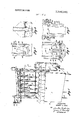
- FIG. 1 is a perspective view of the apparatus for filling receptacles, showing a plurality of receptacles associated with the apparatus, and the manner in which they would be moved by conveyors, or the like, associated with the apparatus;
- FIG. 2 is a schematic view of the apparatus for filling recep tacles, showing the flow of the liquid as it passes from the storage reservoir into the individual receptacles;
- FIG. 3 is a cross-sectional view, with parts broken away, of a dispensing conduit, showing the lower portion of the filler tube;
- FIG. 4 is a cross-sectional view of the lower portion of a dispensing nozzle
- FIG. 5 is a cross-sectional exploded view of the upper por tion of a filler tube, showing the manner in which it is com nected to the remaining components of the dispensing conduit;
- FIG. 6 is a schematic view of the manner in which the dispensed liquid would flow in a receptacle without the presence of the nozzle of FIG. 4;
- FIG. 7 is a schematic view of the apparatus for producing sinusoidal movement of the pusher bar.
- FIG. 1 shows apparatus for filling receptacles with liquid.
- the apparatus is particularly adapted to fill the receptacles with milk, liquid detergent, or any similar liquid that tends to foam or froth when inserted into a receptacle under pressure, or at a high velocity.
- the apparatus has been constructed to accommodate one gallon milk containers; however, it should be understood that receptacles of different configuration can be utilized by minor adjustments of the machine.
- the apparatus 10 comprises a housing 11 supported in the conventional manner by means of legs 12 from a floor surface.
- Housing 11 encloses a pair of pneumatic rams (FIG. 2), and carries a liquid storage reservoir 14 suspended behind, and above its rear surface.
- a centrifugal pump 15 is connected to the side wall 16 of housing 11, and a feed conduit 18 is connected between the inlet ofpump 15 and the lower portion of storage reservoir 14.
- Pump exhaust conduit 19 is connected between the outlet of pump 15 and the inlet of fill manifold 20.
- Cutoff valve 21 is placed in pump exhaust conduit 19, between the outlet of pump 15 and fill manifold 20, to selectively terminate the flow of liquid to fill manifold 21).
- Fill manifold is of a length substantially equal to the width of housing 11, is disposed above storage reservoir 14,
- Manifold bypass conduit 22 is connected to pump exhaust conduit 19 upstream of cutoft valve 21, and communicates with liquid storage reservoir 14.
- a venturi throat 24 is located in manifold bypass conduit 22, adjacent fill manifold 20, and manifold exhaust duct 25 extends between fill manifold 20 and venturi throat 24, in the usual construction, so that flow of liquid through venturi throat 24 creates a low pressure in manifold exhaust duct 25.
- Meter valve 26 is positioned in the manifold bypass conduit, downstream from venturi throat 24. Meter valve 26 is manipulated to control the flow rate of liquid through manifold bypass conduit 22 thus regulating the amount of resulting pressure differentials created in manifold exhaust duct 25.
- a plurality of dispensing conduits 28 are connected to spouts 40 of fill manifold 20, and extend in a downward direction therefrom.
- Dispensing conduits 28 each comprise an outer flow conduit 29, a filler tube 30 (shown in FIG. 2) concentrically positioned within outer flow conduit 29, and slide valve 31 concentrically positioned around outer flow conduit 29.
- Slide valve 31 is constructed so that it reciprocates over the outer surface of outer flow conduit 29.
- outer flow conduit 29 is circular in cross section and defines upper elongate apertures 32 intermediate its ends (FIG. 3) and lower elongate apertures 34 at its lower end (FIG. 4).
- Upper and lower elongate apertures 32 and 34 are disposed so that their longer axes extend in a vertical direction. Also, the lowermost edge of lower apertures 34 extends to the end of outer flow conduit 29 so that no liquid will be entrapped and retained thereby.
- outer flow conduits 29 are connected to spouts 40 of fill manifold 20 by means of connection 35.
- Each outer flow conduit 29 terminates at its upper end in a flange 36 defining an annular groove 38 about its inner periphery.
- the flange portion 36 of the outer flow conduit 29 mates with a flanged portion 39 of spout-O extending from fill manifold 20.
- Gasket 41 is positioned between adjacent edges of flanged portions 36 and in the usual manner, and coupling rings 42 force flanged portions 36 and 39 together to form a fluid-tight seal.
- Filler tube 39 extends from connection downwardly through outer flow conduit 29.
- Fille. tube 30 is constructed with an annular lip 44 extending about its upper end. Lip 44 is ofa thickness slightly less than the thickness of annular groove 38 of the flanged portion 36 of outer flow conduit 29, and the diameter of lip 44 is greater than the interior diameter of outer flow conduit 29, but smaller than the diameter of annular groove 38.
- filler tube 30 is concentrically disposed and retained within outer flow conduit 29 by placement of lip 44 within annular groove 38 of outer flow conduit 29. With this arrangement, filler tube 30 and outer flow conduit 29 define an annular area therebetween which functions as an overflow chamber 45.
- return flow conduit 37 Communicating with overflow chamber 45 and storage reservoir 14 is return flow conduit 37, arranged to provide a return line for quantities of froth, foam or overflow liquid introduced into a receptacle through apertures 34 and subsequently pumped therefrom through apertures 32 into overflow chamber 45.
- the resulting engagement between lip 44 and annular groove 38 is preferably leaky so that in normal operation a quite small flow of liquid passes through this line of engagement.
- This small flow of liquid serves to maintain the connection between filler tube 30 and outer flow conduit 29 in relatively clean condition.
- this flow of liquid serves to flush the dead space within outer flow conduit 29 immediately below flange 44 continuously removing thereby any small droplets of liquid which might form therein.
- this small amount of liquid passes through the line of engagement between tube 30 and conduit 29, it descends within overflow chamber 45 and is either returned to reservoir 14 by way of return flow conduit 37, or it continues to descend and enters receptacles therebelow through upper apertures 32.
- filler tube 30 extends downwardly within outer flow conduit 29 and terminates in an outwardly extending annular flange 46 of a diameter slightly less than the inside diameter of outer flow conduit 29.
- Filler tube 30 is of a length so that its flange 46 is positioned immediately below elongate apertures 32.
- a dam or baffle 48 is supported by means of arms 49 extending from filler tube 30, just beyond the opening 50 of the filler tube.
- Baffle 48 is of circular configuration and approximately equal in diameter to the interior diameter of filler tube 30.
- Nozzle 51 comprises a plurality of lower elongate apertures 34 defined in outer flow conduit 29, and deflector 52.
- Deflector 52 is supported from the end 54 of outer flow conduit 29, and extends coaxially into outer flow conduit 29. Deflector 52 terminates at its upper end in a conical surface 55 having an apex 55' coextensive with the height of apertures 34.
- a threaded shank 56 extends outwardly from end 54 and threadedly receives end cap 58.
- End cap 58 is of a diameter larger than the outside diameter of outer flow conduit 29, and includes an annular recess 59 about its outer periphery, adjacent its upper edge.
- a resilient seal 60 is received in annular recess 59. Annular recess 59 extends inwardly of end 54 so that seal 60 contacts the lower peripheral edge of end 54 and seals threaded shank 56 from contact with a liquid surrounding end cap 58.
- slide valve 31 is cylindrical in shape and includes sealing rings 61 and 62 at its lower and upper ends, respectively. Sealing rings 61 and 62 extend inwardly from slide valve 31, and are of a diameter sufficient to form a sliding seal with the exterior surface of outer flow conduit 29. Thus, slide valve 31 defines, with the exterior surface of outer flow conduit 29, an annular space 64 which is sealed at its ends.
- a spring 65 is disposed about the exterior surface of outer flow conduit 29, above slide valve 31.
- Spring 65 bears against the upper end of slide valve 31, and the lower surface of stationary ring 66 mounted about outer flow conduit 29 below return flow conduit 37 so as to bias slide valve 31 in a downward direction.
- Slide valve 31 is prevented from sliding completely off outer flow conduit 29 since end cap 58 is larger in diameter than the outside diameter of outer flow conduit 29 and sealing ring 61 extends inwardly from slide valve 31 to engage the exterior surface of outer flow conduit 29.
- the lower surface of sealing ring 61 of slide valve 31 engages the upper surface of resilient seal 60 of end cap 58 thereby retaining slide valve 31 in its position around outer flow conduit 29.
- Housing 11 supports a lift platform 68 which is positioned below dispensing conduits 28.
- a pneumatic piston-cylinder combination 69 is provided for raising and lowering lift platform 68 and comprises a cylinder 70 and piston 71 connected by a connection rod 72 to lift platform 68.
- a source of air pressure, 74 is connected by means of conduits 75a and 75b to each end of cylinder 70, and solenoid control valves 76a and 76b are positioned in conduits 75a and 75b, respectively.
- Timer 78 is connected to a source 79 of electricity, and is connected by conductors 80a and 80b to solenoid control valves 76a and 76b, respectively.
- Solenoid control valves 76a and 76b include exhaust openings 82a and 82b, respectively, designed to vent the pressure in conduits 75a and 75b when solenoid control valves 76a and 76b are deenergized.
- solenoid control valve 760 when solenoid control valve 760 is energized and opened by timer 78, compressed air from the source of compressed air 74 communicates through conduit 75a to cylinder 70, to force piston 71 and lift platform 68 in an upward direction.
- timer 78 deenergizes and closes the solenoid of solenoid control valve 76a, the air pressure in conduit 75a and cylinder 70 is vented through exhaust opening 82a to the atmosphere.
- Complementing the deenergization of valve 76a is the energization of valve 7612 which permits air from source 74 to communicate through conduit 75b to cylinder 70 to force piston 71 and platform 68 downwardly.
- Cutoff valve 21 comprises a sanitary pneumatic on-off valve of conventional design and function.
- Source of air pressure 74 is connected by means of conduit 150 to cutoff valve 21 and is selectively supplied to that valve by means of solenoid control valve 152 positioned within conduit 150.
- Timer 78 selectively energizes solenoid control valve 152 .throughconductors 154.
- Solenoid control valve 152 includes an exhaust opening 156 to vent the pressure within conduit 150 when solenoid control valve 152 is deenergized.
- solenoid control valve 152 is energized and opened by timer 78, compressed air from source 74 communicates through conduit 150 to cutoff valve 21 to close that valve and divert the'flow of liquid through manifold bypass conduit 22.
- liquid storagereservoir 14 As the liquid present in liquid storagereservoir 14 is dissipated, more liquid is received through conduit 84 from a reserve supply (not shown). The level of the liquid present in storage reservoir 14 is sensed by the level control 85 which admits more liquid through conduit 84 to tank 14 upon the lowering of the supply therein. Thus, a substantially constant weight of liquid is maintained in storage reservoir 14.
- Arrangement 86 comprises a cylinder 87 disposed behind and parallel to a pusher bar 88.
- Cylinder 87 houses a pair of opposed piston heads 89a and 89b joined to one another by rack 90 centrally located within cylinder 87.
- Cylinder 87 is connected to source of compressed air 74 by a pair of conduits 91a and 91b communicating with opposite ends of cylinder 87.
- a pair of solenoid control valves 92a and 92b are disposed within conduits 91a and 91b, respectively.
- Solenoid control valves 92a and 92b are energized alternately by timer 78 through conductors 94a and 94b, respectively, so that air under pressure from source 74 is alternately supplied to opposite ends of cylinder 87 to alternately drive piston heads 89a and 89b inwardly, thus reciprocating rack 90.
- Exhaust openings 95a and 95b, communicating with solenoid control valves 92a and 92b, respectively, are provided for venting air from cylinder 87 and conduits 91a and 91b.
- pinion 200 Meshing with rack 90 is pinion 200 which has a first lever 202 fixedly attached at one end thereto.
- First lever 202 extends rearwardly in the retractposition and rotates forwardly as piston head 89a is driven inwardly to rotate pinion 200.
- Pivotally attached to the distal end of the first lever 202 is second lever 204 which is pivotally attached at its opposite end to the approximate center of a guide plate 206. It becomes apparent, therefore, that the rotation of pinion 200 causes the reciprocation of guide plate 206 in a plane parallel to its long aXlS.
- each end of guide plate 206 Joining each end of guide plate 206 to each end of pusher bar 88 are a pair of drive rods 208 extending forwardly of guide plate 206.
- movement of guide plate 206 forwardly and rearwardly causes a corresponding movement of pusher bar 88.
- levered piston cylinder arrangement 86 the movement of pusher bar 88 approaches true sinusoidal motion. This type motion is most desirable in the moving of filled receptacles since it is far smoother and has a gently increasing and decreasing velocity. When such motion is employed far less liquid is spilled or sloshed from the filled receptacles.
- lift platform 68 having one piston-cylinder drive arrangement 69 is shown and described, it should be understood that lift platform 68 preferably extends the substantial length of housing 11 under a plurality of dispensing conduits 28, and more than one piston-cylinder drive arrangement may be provided to smoothly and efficiently raise and lower lift platform 68. Moreover, pusher bar preferably extends the length of housing 11 adjacent lift platform 68.
- the present invention is not limited to a specific number of apertures, but includes any grouping of apertures designed to permit the quick, convenient and smooth transfer of liquid to and from a container.
- pump 15 is continuously operated by a source of power, such as an electric motor (not shown) so that pressure is created in pump exhaust conduit 19.
- First conveyors (not shown) are utilized to move a se ries of receptacles 96 onto stationary platform immediately behind lift platform 68 and in front of pusher bar 88.
- solenoid control valve 920 air under pressure flows into one end of cylinder 87 of piston-cylinder arrangement 86 driving piston head 89a inwardly to rotate pinion 200 and drive pusher bar 88 forwardly.
- Pusher bar 88 engages receptacles 96 and drives them forwardly to a position upon lift platform 68 so that the opening of each receptacle is disposed directly below a dispensing conduit 28.
- Timer 78 then deenergizes solenoid control valve 92a venting conduit 91a to the atmosphere and energizes solenoid control valve 92b so that air under pressure drives piston head 89b; inwardly thus rotating pinion 200 and retracting pusher bar 88.
- First conveyors (not shown) then move another series of receptacles onto stationary platform 160 where they remain until driven forwardly by pusher bar 88.
- timer 78 energizes solenoid control valve 764 so that compressed air communicates through conduit 75a from the source of compressed air 74 to the lower end of cylinder 70, thereupon raising lift platform 68, and its receptacles 96.
- the upper edge 98 of its opening or neck 99 engages the lower surface of sealing ring 61 on slide valve 31 of its dispensing conduit 28. Further movement of the receptacle 96 in an upward direction causes slide valve 31 to move a corresponding distance and position conduit 29 in communication with the interior of receptacle 96.
- Timer 78 functions to pneumatically energize cutoff valve 21 as receptacle 96 is being moved in an upward direction so that liquid in pump exhaust conduit 19 is allowed to flow into fill manifold 20.
- the liquid in fill manifold 20 then flows through filler tube until it reaches opening 50, which is below the upper elongate apertures 32 of outer flow conduit 29, where it encounters baffle 48.
- Baffle 48 tends to divert the flow of liquid through dispensing conduit 28 in the direction as indicated by the arrows 100 of FIG. 3.
- the flow of liquid as indicated by arrows 100 produces a slight positive pressure at the line of association between outwardly extending annular flange 46 of filler tube 30 and the interior surface of outer flow conduit 29. Consequently the liquid flowing through opening 50 is not exposed to and mixed with air flowing in through aperture 32 of outer flow conduit 29.
- conical surface 55 has the effect of directing the liquid toward apertures 34 as it enters the vicinity of these apertures.
- Timer 78 is constructed so that cutoff valve 21 is opened to allow liquid to enter fill manifold 20 and flow through filler tube 30 prior to the time nozzle 51 reachesv the bottom of receptacle 96. Thus, liquid flows through nozzle 51 soon after slide valve 31 exposes lower apertures 34 as the receptacle is lifted over dispensing conduit 28.
- timer 78 deenergizes cutoff valve 21 to stop the flow of liquid to manifold 20, and deenergizes solenoid control valve 76a so that the air pressure in the lower portion of cylinder 70 is vented through exhaust opening 82a to the atmosphere.
- platform 68 and receptacles 96 are driven in a downward direction by the introduction of air under pressure into cylinder 70 above piston 71 whereupon sealing rings 61 of slide valves 31 slide over apertures 32 of outer flow conduits 29, thus interrupting communication between the interior of receptacles 96 and overflow chambers 45.
- timer 78 energizes cutoff valve 21 which interrupts the flow of liquid to manifold 20. This places the interior of receptacle 96 in communication with venturi throat 28 to start the volume adjusting operation.
- the liquid normally flowing to manifold 20 is then bypassed through venturi throat 24, through metering valve 26, and back to liquid storage reservoir 14.
- the flow of liquid thorough venturi throat 24 creates a vacuum in manifold exhaust duct 25 and fill manifold 20 so that the pressure created by the column of liquid present in outer flow conduit 29 and filler tube 30 is offset, and the receptive volume of receptacles 96 can be adjusted.
- metering valve 26 allows a faster or slower flow rate through venturi throat 24 to increase or decrease the vacuum drawn in fill manifold 20 and compensate for the varying wall thicknesses of the receptacles 96.
- sealing ring 61 eventually covers lower apertures 34, and comes to rest against annular seal 60 of end cap 58.
- sealing ring 61 reaches this position, the flow of liquid through dispensing conduit 28 is terminated.
- dispensing conduit 28 is fully withdrawn from the interior of the receptacle.
- Timer 78 then energizes solenoid control valve 92a to allow compressed air from compressed air source 74 to flow through conduit 91a, to oneend of cylinder 87, whereupon pusher bar 88 moves a second series of empty receptacles 96 onto lift platform 68.
- the liquid flows over conical surface 55 toward apertures 34 so that the velocity of the components of the liquid as it flows through each opening is substantially uniform throughout the entire length of the opening space, so that maximum effectiveness of the openings is attained. This is in direct contrast to the flow. characteristics shown in FIG. 6 where an open ended flow conduit having no nozzle similar to nozzle 51 thereon, permits a liquid to flow down through the conduit toward the bottom of the receptacle. Upon reaching the bottom of the receptacle, the liquid spreads in an annulus toward the sidewalls of the receptacle.
- the liquid flows generally over the bottom surface of the receptacle and then tends to climb the walls of the receptacle so that a circular turbulence is maintained in the body of the liquid within the receptacle.
- the liquid flowing down through the conduit adjacent the interior wall surface of the conduit tends to maintain its direction of velocity until urged outwardly into the space within the receptacle by the liquid flowing near the center of the conduit which is diverted outwardly by contact with the bottom of the receptacle.
- the particles of liquid flowing through the conduit tend to wedge themselves together to form a high-pressure zone X near the bottom of the receptacle so that the rate of flow of the liquid is increased at this point, further contributing to the high velocity, turbulent flow within the receptacle.
- the nozzle shown in FIG. 4 is.con structed to overcome the above described shortcomihgs andtends to prevent a, speedup of liquid flow at the bottoinjc f'the receptacle. Furthermore,
- the liquid is preferably discharged from thenozzle 51 through trated in FIG. 6 so thattheientrap nent ofgair within liquid,
- timer 78 is energized in the norriicli rna'nner, and .thejsystern is operated without containers 96 beingplaced on platform 68.
- lift platform 68 While lift platform 68 will function. normal, the absenceof receptacles 96 thereon will allow slide valves 31 tor'emainin.
- apertures 32 of outer 'fl ov'v condu'it29 chamber defined between each 1e ube 30 and o uter flow conduit 29, throughleachiijeturr owconduit 31, and
- eachopeiiing 50 of each filler tube causes the'cleaning solution to leakfpast these surfacesl While 5 this leakage does not cause a significant drop inflow rate dur ing the nut-ma] dispensing operation, uringthe cleaning cycle the surfaces of all elements inQthis vicinity are thoroughly cleaned.
- the adjustment of metering valve 26 is relatively inconsequential.
- a vacuum is created within the receptacle sufficient to overcome any vacuum created by venturi throat 24.
- liquid within dispensing conduit 28 is drawn into the receptacle to fill it completely.
- apertures 34 are covered by slide valve 31 penultimate to the breaking of the seal between sealing ring 61 and the upper edge 98 of the receptacle so that no dripping occurs.
- timer 78 may be adjusted so that cutoff valve 21 is held in an open position an extended length of time so as to overfill the receptacle, which has the effect of driving the froth and foam, and a smaller portion of the liquid dispensed into the container through upper apertures 32 of the outer flow conduit 29. This causes not only the froth and foam to be removed from the receptacle, but also a portion of the liquid at or near the surface 102 of the liquid 104 to be expelled.
- Apparatus for filling a flexible walled container with a liquid comprising:
- said volume control means adjusting the receptive volume of said container by selectively adjusting the pressure exerted within said container by said liquid; and said volume control means including venturi means in communication with said liquid in said container, and flow control means for selectively controlling the flow of said liquid through said venturi means to selectively adjust the pressure exerted on the walls of said container by said liquid.
- Apparatus for filling a flexible walled container having an upwardly directed mouth portions through which liquid is introduced comprising:
- a hollow member having discharge means selectively positionable in communication with the interior of the container; filling means selectively connectable to said hollow membe to force the liquid into the container through said discharge means; regulating means selectively connectable to said hollow member and in communication with the interior of the container through said discharge means to adjust the pressure exerted within the container by the liquid and hence the resulting volume of the liquid in the container; and 4 said regulating means including a venturi member defining a reduced diameter throat selectively connectable to said hollow member and flow control means operatively connected to said venturi member to control the flow of the liquid through said throat and thus the pressure exerted on the interior of the container by the liquid.
- the apparatus of claim 3 further including sealing means for selectively sealing the open mouth of the container during the filling thereof.
- sealing means Includes valve means for selectively placing said venting means in communication with the interior of the container while said filling means is connected to said hollow member.
- discharge means are vertical slots defined through said hollow member and said hollow member is stationary, and further including means for moving the container with respect to said hollow member and into engagement with said sealing means.
- a method of filling flexible walled containers with a liquid comprising the steps of:
- Apparatus for filling a flexible walled container with a liquid comprising:
Landscapes
- Engineering & Computer Science (AREA)
- Mechanical Engineering (AREA)
- Basic Packing Technique (AREA)
Description
D United States Patent 1111 3,543,391
[72] Inventor Gerry G. Hull [56] References Cited Atlanta, Ga. UNITED STATES PATENTS m1 APPLNQ 823,816 1,148,574 8/1915 Caspare 14l/52X 22 Flled May27, 1969 2,802,492 8/1957 GOSSfilln... 141/52x [45] Patented Dec-2211970 2,809,677 10/1957 Hamner 141/59 [731 518W w' 3,056,436 10/1962 Fechheimeretal. 141/59 arsaw, n a corporation of Delaware FOREIGN PATENTS continuationofapplicafionse N 608874, .12 1967, 11 5 I99 H Jan nowaba 653,034 5/1961 GreatBritain 141/59 This application May 27, 1969, Ser. No. 828,816
[54] METHOD AND APPARATUS FOR FILLING 37, 39, 52, 59, 65, 66, 374; 53/(Inquired); l37/(lnquired); 222/(Inquired) Primary Examiner-Houston S. Bell, Jr. Attorney-Newton, Hopkins & Ormsby resulting volume of the liquid in the container.
II 26 29 a; 29
METHOD AND APPARATUS FOR FILLING RECEPTACLES CROSS REFERENCE TO OTHER APPLICATIONS This application is a continuation of applicants copending application Ser. No. 608,874, filed Jan. 12 1967, which is now abandoned. 1
BACKGROUND or THE INVENTION When filling containers or receptacles with liquids in a mechanized process, it is desirable to fill the containers as fast as possible to an accurate fill level so that the filling cycle can be repeated as frequently as possible over a given period of time for maximum economy. For maximum speed of opera tion, it is frequently necessary to dispense the liquids into their containers under a pressure which causes, turbulence in the container asthe liquid level rises in the container. For some liquids, the turbulence in the container creates bubbles in the liquid which causes froth or foam on the surface of the liquid in the container. The froth temporarily occupies space that would otherwise be occupied by the liquid dispensed into the container, and after a time lapse, the froth dissipates so that the container is only partially filled. Thus, the container must be initially filled so that the froth on the surface of the liquid overflows the container, or the liquid allowed to settle in the container fora period of time and then more liquid added to the container after the froth dissipates. Furthermore, if the viscosity of the liquid is such that it tends to temporarily trap smaller air bubbles in the main body portion of the liquid, a considerable length of time may be required for the smaller bubbles to rise to the surface of the liquid. Thus, it has been common practice in the filling of containers with liquids that foam or froth, such as milk, liquid detergents, or similar high viscosity liquids, to fill the containers in which the liquids are sold with the use of low liquid pressure and slow flow velocities of the liquid to create a minimum amount of turbulence in the liquid in the container. Of course, low pressures and slow flow velocities of the liquid as it enters the'container sacrifices the speed at which the containers may be filled.
SUMMARY OF THE INVENTION This invention comprises a method and apparatus of filling receptacles with liquids and creating a minimum amount of foam or froth on the surface of the liquid in the receptacles wherein a receptacle is moved to a filling station, below a filling nozzle, the receptacle and nozzle manipulated so that the nozzle is inserted into the receptacle'to a point adjacent its bottom surface, the liquid flowed through the nozzle as it initially enters the receptacle, the air initially present in the receptacle removed from the receptacle opening as the liquid enters the receptacle, and any foam or froth on the rising surface of the liquid removed from the receptacle along with the air initially present in the receptacle-After the receptacle is filled with liquid, the flow of liquid into the receptacle through the nozzle is terminated and a vacuum applied to the nozzle as the nozzle is withdrawn from the receptacle, and as the nozzle is removed from the opening of the receptacle, the openings in the nozzle are blocked to prevent any inadvertent dripping or dispensing of the liquid. i
The apparatus utilized in performing'the above-described method comprises a liquid storage reservoir, a pump having its inlet connected to a lower portion of the storage reservoir and its outlet connected to a fill manifold, acutoff valve disposed between the outlet of the pump and the fill manifold, a plurality of dispensing nozzles extending from the fill manifold, and a bypass line extending from the outlet of the pump back to the storage reservoir, which bypasses the cutoff valve, fill manifold and dispensing nozzles. The bypass line includes a venturi flow portion communicating with the fill manifold and a metering valve for regulating the flow of liquid through the venturi. The dispensing nozzles each include a return flow conduit for returning to the storage reservoir any foam or froth which was created in the receptacles and accumulated on or near the surface of the liquid.
Thus, it is an object of this invention to provide a method of rapidly filling a receptacle with a liquid without creating foam or froth within the body or on the surface of the liquid as it is introduced into the receptacle.
Another object of this invention is to provide a method of rapidly filling a receptacle with a liquid and removing any foam or froth formed on or near the surface of the liquid during the filling operation.
Another object of this invention is to provide a method of rapidly filling a plurality of receptacles with a liquid without spilling the liquid from the receptacles or the dispensing apparatus.
Another object of this invention is to provide apparatus for flowing liquid into containers wherein any foam or froth created on or near the surface of the liquid is removed from the receptacles as the liquid is passed into the containers.
Another object of this invention is to provide a novel nozzle for insertion into a receptacle to introduce liquid into the receptacle adjacent its bottom, surface so that turbulence created by that introduction of liquid is minimized.
Another object of this invention is to provide apparatus for pumping a liquid from a central source of supply into individual receptacles, wherein the flow and pressure of the liquid is accurately controlled throughout the system.
Another object of this invention is to provide apparatus for filling a plurality of receptacles with a liquid from a central source of supply wherein the apparatus is effectively and easily cleansed without disassembly.
Another object of this invention is to provide apparatus for filling individual receptacles with an edible liquid from a central source of supply, wherein the apparatus may be cleaned without disassembly.
Another object of this invention is to provide apparatus for rapidly filling a plurality of individual receptacles with an edible liquid from a central source of supply wherein little or no liquid is wasted, the containers are filled to a predetermined level with a minimum of foam or froth generated on the surface of the liquid, and any foam or froth generated during the filling operation is returned to the central source of supply.
Another object of this invention is to provide apparatus for economically, rapidly and accurately filling a plurality of receptacles with liquid under sanitary conditions.
Other objects, features and advantages of the present invention will become apparent upon reading the following disclosure, taken in conjunction with the accompanying drawing.
DESCRIPTION or THE DRAWING FIG. 1 is a perspective view of the apparatus for filling receptacles, showing a plurality of receptacles associated with the apparatus, and the manner in which they would be moved by conveyors, or the like, associated with the apparatus;
FIG. 2 is a schematic view of the apparatus for filling recep tacles, showing the flow of the liquid as it passes from the storage reservoir into the individual receptacles;
FIG. 3 is a cross-sectional view, with parts broken away, of a dispensing conduit, showing the lower portion of the filler tube;
FIG. 4 is a cross-sectional view of the lower portion of a dispensing nozzle;
FIG. 5 is a cross-sectional exploded view of the upper por tion of a filler tube, showing the manner in which it is com nected to the remaining components of the dispensing conduit;
FIG. 6 is a schematic view of the manner in which the dispensed liquid would flow in a receptacle without the presence of the nozzle of FIG. 4; and
FIG. 7 is a schematic view of the apparatus for producing sinusoidal movement of the pusher bar.
DESCRIPTION OF THE EMBODIMENT Referring now more particularly to the drawing, in which like numerals indicate like parts throughout the several views, FIG. 1 shows apparatus for filling receptacles with liquid. The apparatus is particularly adapted to fill the receptacles with milk, liquid detergent, or any similar liquid that tends to foam or froth when inserted into a receptacle under pressure, or at a high velocity. The apparatus has been constructed to accommodate one gallon milk containers; however, it should be understood that receptacles of different configuration can be utilized by minor adjustments of the machine.
The apparatus 10 comprises a housing 11 supported in the conventional manner by means of legs 12 from a floor surface. Housing 11 encloses a pair of pneumatic rams (FIG. 2), and carries a liquid storage reservoir 14 suspended behind, and above its rear surface. A centrifugal pump 15 is connected to the side wall 16 of housing 11, and a feed conduit 18 is connected between the inlet ofpump 15 and the lower portion of storage reservoir 14. Pump exhaust conduit 19 is connected between the outlet of pump 15 and the inlet of fill manifold 20. Cutoff valve 21 is placed in pump exhaust conduit 19, between the outlet of pump 15 and fill manifold 20, to selectively terminate the flow of liquid to fill manifold 21).
Fill manifold is of a length substantially equal to the width of housing 11, is disposed above storage reservoir 14,
over housing 11, and carries a plurality of spouts 40 (FIG. 5)
communicating therewith.
Manifold bypass conduit 22 is connected to pump exhaust conduit 19 upstream of cutoft valve 21, and communicates with liquid storage reservoir 14. A venturi throat 24 is located in manifold bypass conduit 22, adjacent fill manifold 20, and manifold exhaust duct 25 extends between fill manifold 20 and venturi throat 24, in the usual construction, so that flow of liquid through venturi throat 24 creates a low pressure in manifold exhaust duct 25. Meter valve 26 is positioned in the manifold bypass conduit, downstream from venturi throat 24. Meter valve 26 is manipulated to control the flow rate of liquid through manifold bypass conduit 22 thus regulating the amount of resulting pressure differentials created in manifold exhaust duct 25.
A plurality of dispensing conduits 28 are connected to spouts 40 of fill manifold 20, and extend in a downward direction therefrom. Dispensing conduits 28 each comprise an outer flow conduit 29, a filler tube 30 (shown in FIG. 2) concentrically positioned within outer flow conduit 29, and slide valve 31 concentrically positioned around outer flow conduit 29. Slide valve 31 is constructed so that it reciprocates over the outer surface of outer flow conduit 29. As shown in FIGS. 3 and 4, outer flow conduit 29 is circular in cross section and defines upper elongate apertures 32 intermediate its ends (FIG. 3) and lower elongate apertures 34 at its lower end (FIG. 4). Upper and lower elongate apertures 32 and 34 are disposed so that their longer axes extend in a vertical direction. Also, the lowermost edge of lower apertures 34 extends to the end of outer flow conduit 29 so that no liquid will be entrapped and retained thereby.
As is best shown in FIG. 5, outer flow conduits 29 are connected to spouts 40 of fill manifold 20 by means of connection 35. Each outer flow conduit 29 terminates at its upper end in a flange 36 defining an annular groove 38 about its inner periphery. The flange portion 36 of the outer flow conduit 29 mates with a flanged portion 39 of spout-O extending from fill manifold 20. Gasket 41 is positioned between adjacent edges of flanged portions 36 and in the usual manner, and coupling rings 42 force flanged portions 36 and 39 together to form a fluid-tight seal.
Communicating with overflow chamber 45 and storage reservoir 14 is return flow conduit 37, arranged to provide a return line for quantities of froth, foam or overflow liquid introduced into a receptacle through apertures 34 and subsequently pumped therefrom through apertures 32 into overflow chamber 45.
The resulting engagement between lip 44 and annular groove 38 is preferably leaky so that in normal operation a quite small flow of liquid passes through this line of engagement. This small flow of liquid serves to maintain the connection between filler tube 30 and outer flow conduit 29 in relatively clean condition. Moreover, this flow of liquid serves to flush the dead space within outer flow conduit 29 immediately below flange 44 continuously removing thereby any small droplets of liquid which might form therein. As this small amount of liquid passes through the line of engagement between tube 30 and conduit 29, it descends within overflow chamber 45 and is either returned to reservoir 14 by way of return flow conduit 37, or it continues to descend and enters receptacles therebelow through upper apertures 32.
As is best shown in FIG. 3, filler tube 30 extends downwardly within outer flow conduit 29 and terminates in an outwardly extending annular flange 46 of a diameter slightly less than the inside diameter of outer flow conduit 29. Filler tube 30 is of a length so that its flange 46 is positioned immediately below elongate apertures 32. A dam or baffle 48 is supported by means of arms 49 extending from filler tube 30, just beyond the opening 50 of the filler tube. Baffle 48 is of circular configuration and approximately equal in diameter to the interior diameter of filler tube 30.
As is best shown in FIG. 4, the lower end of outer flow conduit 29 terminates in a nozzle 51. Nozzle 51 comprises a plurality of lower elongate apertures 34 defined in outer flow conduit 29, and deflector 52. Deflector 52 is supported from the end 54 of outer flow conduit 29, and extends coaxially into outer flow conduit 29. Deflector 52 terminates at its upper end in a conical surface 55 having an apex 55' coextensive with the height of apertures 34. A threaded shank 56 extends outwardly from end 54 and threadedly receives end cap 58. End cap 58 is of a diameter larger than the outside diameter of outer flow conduit 29, and includes an annular recess 59 about its outer periphery, adjacent its upper edge. A resilient seal 60 is received in annular recess 59. Annular recess 59 extends inwardly of end 54 so that seal 60 contacts the lower peripheral edge of end 54 and seals threaded shank 56 from contact with a liquid surrounding end cap 58.
As is best shown in FIGS. 2 and 4, slide valve 31 is cylindrical in shape and includes sealing rings 61 and 62 at its lower and upper ends, respectively. Sealing rings 61 and 62 extend inwardly from slide valve 31, and are of a diameter sufficient to form a sliding seal with the exterior surface of outer flow conduit 29. Thus, slide valve 31 defines, with the exterior surface of outer flow conduit 29, an annular space 64 which is sealed at its ends.
A spring 65 is disposed about the exterior surface of outer flow conduit 29, above slide valve 31. Spring 65 bears against the upper end of slide valve 31, and the lower surface of stationary ring 66 mounted about outer flow conduit 29 below return flow conduit 37 so as to bias slide valve 31 in a downward direction. Slide valve 31 is prevented from sliding completely off outer flow conduit 29 since end cap 58 is larger in diameter than the outside diameter of outer flow conduit 29 and sealing ring 61 extends inwardly from slide valve 31 to engage the exterior surface of outer flow conduit 29. Thus, in its lowermost position, the lower surface of sealing ring 61 of slide valve 31 engages the upper surface of resilient seal 60 of end cap 58 thereby retaining slide valve 31 in its position around outer flow conduit 29.
Cutoff valve 21 comprises a sanitary pneumatic on-off valve of conventional design and function. Source of air pressure 74 is connected by means of conduit 150 to cutoff valve 21 and is selectively supplied to that valve by means of solenoid control valve 152 positioned within conduit 150. Timer 78 selectively energizes solenoid control valve 152 .throughconductors 154. Solenoid control valve 152 includes an exhaust opening 156 to vent the pressure within conduit 150 when solenoid control valve 152 is deenergized. Thus, when solenoid control valve 152 is energized and opened by timer 78, compressed air from source 74 communicates through conduit 150 to cutoff valve 21 to close that valve and divert the'flow of liquid through manifold bypass conduit 22. When timer'78 deenergizes the solenoid of solenoid control valve 152, the air pressure within conduit 150 and cutoff valve 21 is vented through exhaust opening 156 tothe atmosphere whereupon cutofr' valve 21 opens and permits the flow of liquid into fill manifold 20.
As the liquid present in liquid storagereservoir 14 is dissipated, more liquid is received through conduit 84 from a reserve supply (not shown). The level of the liquid present in storage reservoir 14 is sensed by the level control 85 which admits more liquid through conduit 84 to tank 14 upon the lowering of the supply therein. Thus, a substantially constant weight of liquid is maintained in storage reservoir 14.
Upon completion of the filling operation, the filled receptacles are moved from beneath dispensing conduits 28 by a levered piston-cylinder arrangement 86. Arrangement 86 comprises a cylinder 87 disposed behind and parallel to a pusher bar 88. Cylinder 87 houses a pair of opposed piston heads 89a and 89b joined to one another by rack 90 centrally located within cylinder 87. Cylinder 87 is connected to source of compressed air 74 by a pair of conduits 91a and 91b communicating with opposite ends of cylinder 87. A pair of solenoid control valves 92a and 92b are disposed within conduits 91a and 91b, respectively. Solenoid control valves 92a and 92b are energized alternately by timer 78 through conductors 94a and 94b, respectively, so that air under pressure from source 74 is alternately supplied to opposite ends of cylinder 87 to alternately drive piston heads 89a and 89b inwardly, thus reciprocating rack 90. Exhaust openings 95a and 95b, communicating with solenoid control valves 92a and 92b, respectively, are provided for venting air from cylinder 87 and conduits 91a and 91b.
Meshing with rack 90 is pinion 200 which has a first lever 202 fixedly attached at one end thereto. First lever 202 extends rearwardly in the retractposition and rotates forwardly as piston head 89a is driven inwardly to rotate pinion 200. Pivotally attached to the distal end of the first lever 202 is second lever 204 which is pivotally attached at its opposite end to the approximate center of a guide plate 206. It becomes apparent, therefore, that the rotation of pinion 200 causes the reciprocation of guide plate 206 in a plane parallel to its long aXlS.
Joining each end of guide plate 206 to each end of pusher bar 88 are a pair of drive rods 208 extending forwardly of guide plate 206. Thus, movement of guide plate 206 forwardly and rearwardly causes a corresponding movement of pusher bar 88. Moreover, due to the employment of levered piston cylinder arrangement 86, the movement of pusher bar 88 approaches true sinusoidal motion. This type motion is most desirable in the moving of filled receptacles since it is far smoother and has a gently increasing and decreasing velocity. When such motion is employed far less liquid is spilled or sloshed from the filled receptacles.
While one lift platform 68 having one piston-cylinder drive arrangement 69 is shown and described, it should be understood that lift platform 68 preferably extends the substantial length of housing 11 under a plurality of dispensing conduits 28, and more than one piston-cylinder drive arrangement may be provided to smoothly and efficiently raise and lower lift platform 68. Moreover, pusher bar preferably extends the length of housing 11 adjacent lift platform 68.
In addition, it should be understood that even though four upper apertures 32 and four lower apertures 34 have been shown, the present invention is not limited to a specific number of apertures, but includes any grouping of apertures designed to permit the quick, convenient and smooth transfer of liquid to and from a container.
OPERATION When it is desired to fill receptacles, such as receptacles 96 with liquid from liquid storage tank 14, pump 15 is continuously operated by a source of power, such as an electric motor (not shown) so that pressure is created in pump exhaust conduit 19. First conveyors (not shown) are utilized to move a se ries of receptacles 96 onto stationary platform immediately behind lift platform 68 and in front of pusher bar 88. Upon energizing solenoid control valve 920, air under pressure flows into one end of cylinder 87 of piston-cylinder arrangement 86 driving piston head 89a inwardly to rotate pinion 200 and drive pusher bar 88 forwardly. Pusher bar 88 engages receptacles 96 and drives them forwardly to a position upon lift platform 68 so that the opening of each receptacle is disposed directly below a dispensing conduit 28. Timer 78 then deenergizes solenoid control valve 92a venting conduit 91a to the atmosphere and energizes solenoid control valve 92b so that air under pressure drives piston head 89b; inwardly thus rotating pinion 200 and retracting pusher bar 88. First conveyors (not shown) then move another series of receptacles onto stationary platform 160 where they remain until driven forwardly by pusher bar 88.
lmmediately after pusher bar 88 positions the receptacles 96 upon lift platform 68, timer 78 energizes solenoid control valve 764 so that compressed air communicates through conduit 75a from the source of compressed air 74 to the lower end of cylinder 70, thereupon raising lift platform 68, and its receptacles 96. As each receptacle 9,6 is raised in this manner, the upper edge 98 of its opening or neck 99 engages the lower surface of sealing ring 61 on slide valve 31 of its dispensing conduit 28. Further movement of the receptacle 96 in an upward direction causes slide valve 31 to move a corresponding distance and position conduit 29 in communication with the interior of receptacle 96. As slide valve 31 moves in an upward direction with receptacle 96, lower elongate apertures 34 at the lower end of outer flow conduit 29 are exposed to the interior of receptacles 96. Further upward movement of receptacles 96 moves slide valves 31, against the bias of their springs 65, until upper elongate apertures 32 intermediate the ends of outer flow conduits 29 are exposed to the interior of containers 96.
Since a perfectly tight seal is not generated between flange 46 and the interior surface of outer flow conduit 29, a minute flow of liquid upwardly therebetween may be generated. This flow is actually quite advantageous to the overall operation of the apparatus since it serves to cleanse the line of association between flange 46 and outer flow conduit 29 without noticeably lowering the quantity of liquid flow into the receptacle. Of course, any liquid which does pass between flange 46 and conduit 29 is returned to the reservoir 14 through overflow chamber 45 and return flow conduit 37. The vast majority of the liquid then flows through the remaining length of the outer flow conduit 29, toward nozzle 51 at the end thereof. As the liquid progresses toward nozzle 51, the portion of the liquid near the center of outer flow conduit 29 engages conical surface 55 of deflector 52 and is diverted toward the upper portion of lower apertures 34, as indicated by arrows 101 in H6. 4. Thus, conical surface 55 has the effect of directing the liquid toward apertures 34 as it enters the vicinity of these apertures.
When sealing ring 61 of slide valve 31 moves about upper apertures 32 of outer flow conduit 29, the air present in container 96 is free to flow through the overflow chamber 45 defined between filler tube 30 and outer flow conduit 29, and through return flow conduit 37. to be vented to the liquid storage reservoir 14. As the surface 102 of the liquid 104 in container 96 covers apertures 34 of nozzle 51, the tendency of the liquid flowing through nozzle 51, to generate froth or foam on its surface 102 is substantially reduced. As surface 102 of liquid 104 rises toward the opening 99 of the container 96, any froth or foam present thereon will be forced through upper apertures 32 and be vented back to liquid storage reservoir 14 through conduit 37. After the necessary time interval for filling a receptacle 96, timer 78 deenergizes cutoff valve 21 to stop the flow of liquid to manifold 20, and deenergizes solenoid control valve 76a so that the air pressure in the lower portion of cylinder 70 is vented through exhaust opening 82a to the atmosphere. As the air escapes from cylinder 70, platform 68 and receptacles 96 are driven in a downward direction by the introduction of air under pressure into cylinder 70 above piston 71 whereupon sealing rings 61 of slide valves 31 slide over apertures 32 of outer flow conduits 29, thus interrupting communication between the interior of receptacles 96 and overflow chambers 45. At that point, timer 78 energizes cutoff valve 21 which interrupts the flow of liquid to manifold 20. This places the interior of receptacle 96 in communication with venturi throat 28 to start the volume adjusting operation. The liquid normally flowing to manifold 20 is then bypassed through venturi throat 24, through metering valve 26, and back to liquid storage reservoir 14. The flow of liquid thorough venturi throat 24 creates a vacuum in manifold exhaust duct 25 and fill manifold 20 so that the pressure created by the column of liquid present in outer flow conduit 29 and filler tube 30 is offset, and the receptive volume of receptacles 96 can be adjusted. When filling nonrigid receptacles such as plastic milk jugs, regulation of the fill level is difficult because the sidewalls thereof bow out under the weight of the liquid therein to change the receptive volume thereof. Since the wall thicknesses of these receptacles vary from batch to batch, the unregulated receptive volume of each batch of receptacles varies, but a standard receptive volume for each batch may be obtained by regulation of the metering valve 26 which will cause the walls of the nonrigid receptacle to contract inwardly in varying degrees to adjust the resulting volume of the liquid in each receptacle 96 to a standard:
volume. Upon breaking the seal between sealing ring 61 and upper edge 98, the walls of the nonrigid receptacle will then expand back totheir normal position, creating a larger volume within the receptacle and allowing the fill level to drop to a desired position. Moreover, adjustment of metering valve 26 allows a faster or slower flow rate through venturi throat 24 to increase or decrease the vacuum drawn in fill manifold 20 and compensate for the varying wall thicknesses of the receptacles 96.
As receptacle 96 continues .to move in a downward direction, sealing ring 61 eventually covers lower apertures 34, and comes to rest against annular seal 60 of end cap 58. When sealing ring 61 reaches this position, the flow of liquid through dispensing conduit 28 is terminated. As receptacle 96 is moved to its full down position, dispensing conduit 28 is fully withdrawn from the interior of the receptacle. Timer 78 then energizes solenoid control valve 92a to allow compressed air from compressed air source 74 to flow through conduit 91a, to oneend of cylinder 87, whereupon pusher bar 88 moves a second series of empty receptacles 96 onto lift platform 68. As this second series of receptacles moves onto the lift platform,-. they engage and discharge the first series of receptacles 96 off the lift platform and onto a second conveyor (not shown) which moves the filled receptacles to a position remote from apparatus 10. Timer 78 then deactivates solenoid control valve 92a whereupon the air pressure present in cylinder 87 and its conduit 91a is vented through exhaust opening 950 to the atmosphere, and then activates solenoid control valve 92b to drive piston head 89b inwardly thus rotating pinion 200 and retracting pusher bar 88. At this point, stationary platform receives another series of empty receptacles 96 which were positioned thereon by the first conveyor (not shown).
Referring now to FIG. 4, it will be noted that the liquid flows over conical surface 55 toward apertures 34 so that the velocity of the components of the liquid as it flows through each opening is substantially uniform throughout the entire length of the opening space, so that maximum effectiveness of the openings is attained. This is in direct contrast to the flow. characteristics shown in FIG. 6 where an open ended flow conduit having no nozzle similar to nozzle 51 thereon, permits a liquid to flow down through the conduit toward the bottom of the receptacle. Upon reaching the bottom of the receptacle, the liquid spreads in an annulus toward the sidewalls of the receptacle. The liquid flows generally over the bottom surface of the receptacle and then tends to climb the walls of the receptacle so that a circular turbulence is maintained in the body of the liquid within the receptacle. The liquid flowing down through the conduit adjacent the interior wall surface of the conduit tends to maintain its direction of velocity until urged outwardly into the space within the receptacle by the liquid flowing near the center of the conduit which is diverted outwardly by contact with the bottom of the receptacle. Thus, the particles of liquid flowing through the conduit tend to wedge themselves together to form a high-pressure zone X near the bottom of the receptacle so that the rate of flow of the liquid is increased at this point, further contributing to the high velocity, turbulent flow within the receptacle. As the liquid flows in this manner, it tends to entrap any air bubbles already entrained therein within the body of the liquid present in the receptacle, and the turbuleince of the liquid, nearits surface withintherecepta' entrapand engorgetheair,
above the liquid} The nozzle shown in FIG. 4 is.con structed to overcome the above described shortcomihgs andtends to prevent a, speedup of liquid flow at the bottoinjc f'the receptacle. Furthermore,
the liquid is preferably discharged from thenozzle 51 through trated in FIG. 6 so thattheientrap nent ofgair within liquid,
is minimized;
Attention is invited to the .factthatthe various components of the apparatus hereindisclosed'are constructed sothat they may be automaticallycleaned when the system is notjin use...
For instance, when the dispensing function has, been quid storage reservoir 14 is;
completed for a periddibffiiiie, I partially filled with a cleansing] and the pumplS energized to pressurize the fsystern th the cleansing liquid. ,The
While lift platform 68 will function. normal, the absenceof receptacles 96 thereon will allow slide valves 31 tor'emainin.
their down or closed position. Thusgwhencutoff valve 21 is the cleansing liquid will flow downw dlyithrough each fillertube 30, through the lower portion ach outerflow conduit 29, out through each group of lo opened so. that'manifold',20 is filleld with'cleansing.solution, 1 o
. a rtures 34, into the annularspac'es 64 defined between outer menses and slidevalves 31, upwardly to and .thrciij'gh each group oflupper,
back into each storage reservoirfi t. Whenjcu'toff 21 is deenergized to terminate commit haust conduit 19 and fill mariif flows through manifold bypass c metervalve 2 6, and back to liq" i s i sq h v'enturi throat 24, "storag reservoir Thus,
a vacuum is applied through manifoldieihaiist duct so that atiori' between pump. exv the cleaning solution flows through these elements. After the apparatus'has been cycled in this mannenlreceptaclesflo may filledwith the cleansing solution.1Thus,I endcaps 58 and their be placed'on lift'platform 6 8 so'th'atlthe'receptacles will be seals 60, and the lower surface-of sealing rings 61 of slide valves 3l will be contacted and cleaned by the cleaning solu tion.
As'is shown in FIG.) and previously discussed, the radially outwardly extending flange 46 at the'lo we r, endof filler tube 30 formsa'leaky seal with the interiorl surface of outer flow conduit 29 sothat liquid leaks past these surfaces. Thus,.the
sit flows'through pressure created in the cleanings ut' p gainsteachbaffle 48,
eachopeiiing 50 of each filler tube causes the'cleaning solution to leakfpast these surfacesl While 5 this leakage does not cause a significant drop inflow rate dur ing the nut-ma] dispensing operation, uringthe cleaning cycle the surfaces of all elements inQthis vicinity are thoroughly cleaned. i
As shown in FIG. 5 and previouslydiscussed, lip44,of filler,
flows through eachlspplut ltl extending fronifill manifoldlt), a small pfortion of the Icleaiising 'liquidjlpasses through and arouiid each line of engagement between lip. 44 and annular.
If it is desired "to inspector furtherhcleanslide valve 3l, end ofouter flow conduit shank 56 whereupon slidevalvei3d ie eh I conduit 29;.
The easewith which ,slidevalve 31 is removed from outer flow nsu 2 5 ai n s lae ns li valves during t dispensing operation. Eon instance,,if the sealing rings 61 or 62 at the 56. A replacem entvo f this nature would probably require less I than one minutefs shutdown time of the apparatus. While the slide :yalve 3i and end, cap 58 are easily replaced, their seals are silrnple iriconstruction and easyto replace, Thus, if sub-, stitute slide valvesorendcaps 5 8 are not available, seals 60,; v 61 or 62 can be easilyreplaced with a minimum of shutdown etsqs rs t h aps r t t It should be notedghat if .aesrnallernumber of receptacles; areconveyed to the apparatus than there are filling stations present on the apparatus, when .platform 68 is raised, those receptacles 96 present on platform: 68- will be filled; however,
the absence of areceptacleQlS on one, portion of the platform 3 will not function to. interrupt the operation of the machine nor cause the machine to malfunction since the slide valve non,
mally associated with a receptacle on that portion of the platforrn..will merely rernainin its down or closed position and the liquid circulated through, filler-tube.30 and the lower portion h of outer tlow=conduit 29 will merely recirculate back through the annular space 64, defined between the interiorsurface of sl idel valve 31 and the exterior surface of outer flow conduit 29, throughupper, apertures 32, through overflow chamber 45 defined between the outersurface of filler tube 30 and the interiorsurface of QttlZCfRflQWjQOHdUlI 29, through return flow cOndtiitSLand baclcinto storage reservoir 14. Thus, no liquid will leak or otherwise be wasted in the operation of the apaws w th: apvetaww nctio normally with sP c to the receptacles presentonplatform 68.
While the apparatus herein disclosed has been specifically} constructed to fill. one gallon, jugswith milk, it should be unl derstood thatbothrigidand nonrigid receptacles of different sizes ,arid shapes can ,be filled with similar apparatus adapted to the particular configuration of the receptacles. Further-1 more,. .th e liquid flowing, through the system can be other than milk, his-anticipated thet -any liquid of normal viscosity and 1 properties can behandledby the system. it should be noted, 1 however, :that the apparatus herein disclosed is particularly adaptedto .handl e liquids that normally froth or foam when, moved .with a, turbulentflow; Of course, liquids that do not i a y. f t fq mdsr ns-mt u s fl n l b died by, the apparatus herein disclosed.
While the apparatus herein disclosed has stations forfilling 3 five;receptacles, at a time, it should be understoodthat the scopeofthis invention should not be limited to the number of stations illustrated, furthermore, while a particular electrical control circuit has beendisclosed in conjunction with pneu matic; controls, itjshould be; understood that platform 68 and pusher bar may, be electrically controlled or that cutoff valvel 2l may ,be electrically or hydraulically controlled; Furthermore, while a particular timing sequence has been dis! closed,it not beyond the scope of this invention to, vary the timingv .of pperatiorrpf the various components disclosed. For
instance, the systern will operate properly when cutoff valve 21 is openedbefore areceptacle 9 6 moves slide valve fildn an 1 upwarddirectiom-of course,whenthe apparatus functions in this manner, liquid flows throughnozzleSl of outer flow con: duit 2 9under a full head of pressure as soonas lower aper; tures,34 are uncoveredby sealingrings 61. While this may slightly increase thefoamand froth encountered onthe surface 192 oftheliquidlMwithin-the receptacles 96 the. receptacles will be filledata fasterrate, Since, the foam and froth are expelled from the. receptaclesas the liquidrises therein, Y
the presence. of the extra foamonfroth is insignificant.
at or near the upper edge 98 of the receptacle opening 99, the adjustment of metering valve 26 is relatively inconsequential. As dispensing conduit 28 is removed from receptacle 96, a vacuum is created within the receptacle sufficient to overcome any vacuum created by venturi throat 24. Thus, liquid within dispensing conduit 28 is drawn into the receptacle to fill it completely. Furthermore, apertures 34 are covered by slide valve 31 penultimate to the breaking of the seal between sealing ring 61 and the upper edge 98 of the receptacle so that no dripping occurs.
If the froth or foam encountered with the receptacle 96 is excessive, due to temperature conditions or the particular substance being dispensed, timer 78 may be adjusted so that cutoff valve 21 is held in an open position an extended length of time so as to overfill the receptacle, which has the effect of driving the froth and foam, and a smaller portion of the liquid dispensed into the container through upper apertures 32 of the outer flow conduit 29. This causes not only the froth and foam to be removed from the receptacle, but also a portion of the liquid at or near the surface 102 of the liquid 104 to be expelled. Under normal circumstances, the liquid at the upper end of the receptacle will have entrapped therein a proportionately greater amount of bubbles, froth and foam. Thus, this aerated portion of the liquid is actually driven from the receptacle and returned to the reservoir.
lt will be obvious to those skilled in the art that many variations may be made in the embodiment chosen for the purpose of illustrating the present invention without departing from the scope thereof as defined by the appended claims.
lclaim:
1. Apparatus for filling a flexible walled container with a liquid comprising:
means for introducing said liquid into said container;
means for controlling the resulting volume of said liquid in said container by adjusting the receptive volume of said container;
means for sealing said container during the filling thereof;
said volume control means adjusting the receptive volume of said container by selectively adjusting the pressure exerted within said container by said liquid; and said volume control means including venturi means in communication with said liquid in said container, and flow control means for selectively controlling the flow of said liquid through said venturi means to selectively adjust the pressure exerted on the walls of said container by said liquid.
2. Apparatus for filling a flexible walled container having an upwardly directed mouth portions through which liquid is introduced comprising:
a hollow member having discharge means selectively positionable in communication with the interior of the container; filling means selectively connectable to said hollow membe to force the liquid into the container through said discharge means; regulating means selectively connectable to said hollow member and in communication with the interior of the container through said discharge means to adjust the pressure exerted within the container by the liquid and hence the resulting volume of the liquid in the container; and 4 said regulating means including a venturi member defining a reduced diameter throat selectively connectable to said hollow member and flow control means operatively connected to said venturi member to control the flow of the liquid through said throat and thus the pressure exerted on the interior of the container by the liquid.
3. The apparatus of claim 2 wherein said hollow member has venting means selectively positionable in communication with the interior of the container through the mouth for selectively venting the interior of the container.
4. The apparatus of claim 3 further including sealing means for selectively sealing the open mouth of the container during the filling thereof.
5. The apparatus of claim 4 wherein said sealing means Includes valve means for selectively placing said venting means in communication with the interior of the container while said filling means is connected to said hollow member.
6. The apparatus of claim 5 wherein said discharge means are vertical slots defined through said hollow member and said hollow member is stationary, and further including means for moving the container with respect to said hollow member and into engagement with said sealing means.
7. A method of filling flexible walled containers with a liquid comprising the steps of:
a. introducing liquid into said container;
b. venting said container to the atmosphere while filling;
c. selectively sealing said container; and
d. subsequently adjusting the pressure exerted on the walls of said container by said liquid to adjust the receptive volume of said container and thus the resulting volume of said liquid in said container.
8. Apparatus for filling a flexible walled container with a liquid comprising:
a. means for introducing liquid into said container;
b. means for venting said container to the atmosphere while 0. means for selectively sealing said container; and
d. means for adjusting the pressure exerted on the walls of said container by said liquid to adjust the receptive volume of said container and thus the resulting volume of said liquid in said container.
Applications Claiming Priority (1)
| Application Number | Priority Date | Filing Date | Title |
|---|---|---|---|
| US82881669A | 1969-05-27 | 1969-05-27 |
Publications (1)
| Publication Number | Publication Date |
|---|---|
| US3548891A true US3548891A (en) | 1970-12-22 |
Family
ID=25252816
Family Applications (1)
| Application Number | Title | Priority Date | Filing Date |
|---|---|---|---|
| US828816A Expired - Lifetime US3548891A (en) | 1969-05-27 | 1969-05-27 | Method and apparatus for filling receptacles |
Country Status (1)
| Country | Link |
|---|---|
| US (1) | US3548891A (en) |
Cited By (7)
| Publication number | Priority date | Publication date | Assignee | Title |
|---|---|---|---|---|
| US3699740A (en) * | 1970-01-29 | 1972-10-24 | Holstein & Kappert Maschf | Method and apparatus for filling bottles or cans with beer or the like |
| DE3337352A1 (en) * | 1983-10-14 | 1985-05-02 | Gerhard 2000 Hamburg Grosskreuz | SYSTEM FOR SIMULTANEOUSLY FILLING A LIQUID, GASEOUS OR SOLID, FLOWABLE MEDIUM IN MULTIPLE CONTAINERS, LIKE CONTAINERS, BARRELS, PACKS OR THE LIKE. |
| EP0105197A3 (en) * | 1982-09-07 | 1985-05-15 | Gerhard Grosskreuz | Device for simultaneously filling a plurality of containers such as receptacles, casks, packages or the like with a liquid, gaseous or solid substance |
| AT382852B (en) * | 1982-09-07 | 1987-04-27 | Grosskreuz Gerhard | DEVICE FOR SIMULTANEOUSLY FILLING A FLOWABLE MEDIUM IN MULTIPLE CONTAINERS, LIKE CONTAINERS, BARRELS, PACKS OD. DGL. |
| DE19907935A1 (en) * | 1999-02-24 | 2000-09-07 | Basf Ag | Apparatus for dosing fluids, e.g. fluid samples that are toxic or infectious has a dosing opening and an outlet opening enclosed by a container |
| US20090283177A1 (en) * | 2006-05-13 | 2009-11-19 | Haas Gernod | Method and device for the controlled foaming of a product introduced in bottles or similar containers |
| US10519017B2 (en) * | 2014-07-21 | 2019-12-31 | Patent Agencies Limited | Filler machine |
-
1969
- 1969-05-27 US US828816A patent/US3548891A/en not_active Expired - Lifetime
Cited By (12)
| Publication number | Priority date | Publication date | Assignee | Title |
|---|---|---|---|---|
| US3699740A (en) * | 1970-01-29 | 1972-10-24 | Holstein & Kappert Maschf | Method and apparatus for filling bottles or cans with beer or the like |
| EP0105197A3 (en) * | 1982-09-07 | 1985-05-15 | Gerhard Grosskreuz | Device for simultaneously filling a plurality of containers such as receptacles, casks, packages or the like with a liquid, gaseous or solid substance |
| AT382852B (en) * | 1982-09-07 | 1987-04-27 | Grosskreuz Gerhard | DEVICE FOR SIMULTANEOUSLY FILLING A FLOWABLE MEDIUM IN MULTIPLE CONTAINERS, LIKE CONTAINERS, BARRELS, PACKS OD. DGL. |
| DE3337352A1 (en) * | 1983-10-14 | 1985-05-02 | Gerhard 2000 Hamburg Grosskreuz | SYSTEM FOR SIMULTANEOUSLY FILLING A LIQUID, GASEOUS OR SOLID, FLOWABLE MEDIUM IN MULTIPLE CONTAINERS, LIKE CONTAINERS, BARRELS, PACKS OR THE LIKE. |
| EP0138212A3 (en) * | 1983-10-14 | 1985-06-05 | Gerhard Grosskreuz | |
| EP0196410A1 (en) * | 1983-10-14 | 1986-10-08 | Gerhard Grosskreuz | Device for simultaneously filling a plurality of containers such as receptacles, vats, packages or the like with a liquid or solid fluid substance |
| US4651788A (en) * | 1983-10-14 | 1987-03-24 | Gerhard Grosskreuz | Apparatus for simultaneously filling a plurality of containers with liquid, gaseous or solid substances |
| WO1988003893A1 (en) * | 1983-10-14 | 1988-06-02 | Gerhard Grosskreuz | Installation for simultaneously filling several packing drums, such as containers, barrels, packages or the like, with a liquid, gaseous or solid fluid medium |
| DE19907935A1 (en) * | 1999-02-24 | 2000-09-07 | Basf Ag | Apparatus for dosing fluids, e.g. fluid samples that are toxic or infectious has a dosing opening and an outlet opening enclosed by a container |
| US20090283177A1 (en) * | 2006-05-13 | 2009-11-19 | Haas Gernod | Method and device for the controlled foaming of a product introduced in bottles or similar containers |
| US8037907B2 (en) * | 2006-05-13 | 2011-10-18 | Khs Ag | Method and device for the controlled foaming of a product introduced in bottles or similar containers |
| US10519017B2 (en) * | 2014-07-21 | 2019-12-31 | Patent Agencies Limited | Filler machine |
Similar Documents
| Publication | Publication Date | Title |
|---|---|---|
| CA1284790C (en) | Dosing system | |
| US6148874A (en) | Filling head mechanism that removes material from a spout of a filled container before completely disengaging from the spout | |
| US4410108A (en) | Pressure-actuated valve for use with positive displacement filling machine | |
| US5255720A (en) | Method and apparatus for dripless filling of containers | |
| EP0853041B1 (en) | High-speed liquid filling machine | |
| US2492873A (en) | Valved nozzle | |
| US4967931A (en) | Bottom-up filler | |
| US3522824A (en) | Automatic container filling apparatus | |
| US5009339A (en) | Method of and an apparatus for venting a filling plant | |
| CA1315751C (en) | Apparatus for minimizing foam in filling containers | |
| US4317475A (en) | Liquid filling and level sensing apparatus | |
| JPS6352234B2 (en) | ||
| US3799222A (en) | Container filling apparatus | |
| EP0103484A2 (en) | Filling machine for foaming liquids | |
| ITMI971668A1 (en) | MACHINE FOR FILLING CONTAINERS IN PARTICULAR FOR FILLING BOTTLES AND RELATIVE FILLING METHOD | |
| US3335921A (en) | Liquid dispensing apparatus | |
| US4840205A (en) | Method and apparatus for dispensing liquids | |
| GB1233356A (en) | ||
| JPH08301392A (en) | Liquid filling nozzle | |
| KR100306614B1 (en) | Apparatus for automatically filling cosmetic liquid | |
| CN210457410U (en) | Multi-path micro-fluid high-precision filling system | |
| US3450172A (en) | Device for filling containers of semi-rigid or soft material such as plastic bottles | |
| US1675208A (en) | Apparatus for filling containers | |
| US4544006A (en) | Apparatus for filling dispensing containers with a liquid or pasty product | |
| CN219839461U (en) | Cosmetic split charging device |