EP0103374B1 - Streuende Abdeckung für Kraftfahrzeugscheinwerfer - Google Patents
Streuende Abdeckung für Kraftfahrzeugscheinwerfer Download PDFInfo
- Publication number
- EP0103374B1 EP0103374B1 EP83304167A EP83304167A EP0103374B1 EP 0103374 B1 EP0103374 B1 EP 0103374B1 EP 83304167 A EP83304167 A EP 83304167A EP 83304167 A EP83304167 A EP 83304167A EP 0103374 B1 EP0103374 B1 EP 0103374B1
- Authority
- EP
- European Patent Office
- Prior art keywords
- trough
- cover
- ridge
- region
- diffusion
- Prior art date
- Legal status (The legal status is an assumption and is not a legal conclusion. Google has not performed a legal analysis and makes no representation as to the accuracy of the status listed.)
- Expired
Links
- 238000009792 diffusion process Methods 0.000 title claims description 45
- 230000003247 decreasing effect Effects 0.000 claims description 8
- 230000000694 effects Effects 0.000 description 6
- 230000004313 glare Effects 0.000 description 4
- 239000011521 glass Substances 0.000 description 4
- 230000002093 peripheral effect Effects 0.000 description 3
- 238000010586 diagram Methods 0.000 description 2
- 239000000853 adhesive Substances 0.000 description 1
- 230000001070 adhesive effect Effects 0.000 description 1
- 230000033228 biological regulation Effects 0.000 description 1
- 238000010276 construction Methods 0.000 description 1
- 230000007423 decrease Effects 0.000 description 1
- 238000006073 displacement reaction Methods 0.000 description 1
- 238000002474 experimental method Methods 0.000 description 1
- 230000014509 gene expression Effects 0.000 description 1
- 238000011905 homologation Methods 0.000 description 1
- 238000005286 illumination Methods 0.000 description 1
- 239000000463 material Substances 0.000 description 1
- 239000000565 sealant Substances 0.000 description 1
- 230000007704 transition Effects 0.000 description 1
Images

Classifications
-
- F—MECHANICAL ENGINEERING; LIGHTING; HEATING; WEAPONS; BLASTING
- F21—LIGHTING
- F21S—NON-PORTABLE LIGHTING DEVICES; SYSTEMS THEREOF; VEHICLE LIGHTING DEVICES SPECIALLY ADAPTED FOR VEHICLE EXTERIORS
- F21S41/00—Illuminating devices specially adapted for vehicle exteriors, e.g. headlamps
- F21S41/20—Illuminating devices specially adapted for vehicle exteriors, e.g. headlamps characterised by refractors, transparent cover plates, light guides or filters
- F21S41/28—Cover glass
Definitions
- This invention relates to a diffusion cover for a motor vehicle headlamp and is particularly concerned with a diffusion cover of the type comprising upper and lower mutually inclined translucent cover portions which define therebetween a peak line or ridge on an outer surface of the cover and a trough on an inner surface of the cover.
- Diffusion covers of the above type having been proposed for styling and streamlining purposes so that the outer surface of the diffusion cover has a shape which merges with the outer shape of the front of the vehicle body.
- Examples of such diffusion covers for motor vehicles are disclosed in GB-A-1158069 and GB-A-1079954.
- Such diffusion covers are generally moulded from glass so that the front and rear surfaces of the cover portions are substantially parallel with each other.
- glass cannot be successfully moulded with very sharp edges, this results in the ridge and the trough being radiussed.
- the results of this is that there is defined effectively a concavo-convex lens which imparts a vertical spread of light.
- Such a vertical spread of light is to be avoided because it leads to glare problems. In other words, it is difficult for motor vehicle headlamps fitted with such diffusion covers to satisfy the stringent photomeric requirements for homologation purposes.
- An object of the present invention is to provide a diffusion cover of the above type in which the above mentioned disadvantage is obviated or mitigated.
- a diffusion cover for diffusion a beam of light rays from the reflector of a motor vehicle headlamp, said cover comprising upper and lower mutually inclined translucent cover portions which are integrally joined together to define therebetween a ridge on an outer surface of the cover and a trough on an inner surface of the cover, the trough being disposed above the ridge, characterised in that the inner surface of the upper cover portion in the region of the trough is of concave form so that the prism angle in said region increases with decreasing distance from the trough, the inner surface of the lower cover portion in the region of the trough is of convex form so that the prism angle in said region increases with decreasing distance from the trough, and the disposition of the inner and outer surfaces of each cover portion in the respective regions of the ridge and the trough relative to the direction of incident light rays from the beam is such that the light rays which are incident upon the inner surface of said regions of the upper and lower cover portions in use are not refracted upwardly upon passage
- a motor vehicle headlamp comprising a reflector having an internal paraboloidal reflective surface; means for mounting a light source relative to the reflector so that a substantially parallel beam of light from the light source is reflected by the reflector when the light source is energised; and a diffusion cover through which the beam of light passes in use out of the headlamp, said diffusion cover comprising upper and lower mutually inclined translucent cover portions which are integrally joined together to define therebetween a ridge on an outer surface of the cover and a trough on an inner surface of the cover, the trough being disposed above the ridge, characterised in that the inner surface of the upper cover portion in the region of the trough is of concave form so that the prism angle in said region increases with decreasing distance from the trough, the inner surface of the lower cover portion in the region of the trough is of convex form so that the prism angle in said region increases with decreasing distance from the trough, and the disposition of the inner and outer surfaces of each cover portion in
- the degree of concavity and convexity of the inner surface regions of the upper and lower cover portions depends upon various factors, such as the refractive index of the material of construction of the diffusion cover, the angle of mutual inclination of the upper and lower portions, the vertical spacing between the trough and the ridge, and the radii of curvature of the trough and the ridge.
- the thickness of the lower cover portion is at a minimum in the region of its joint with the upper cover portion and increases over the region thereof which has a convex inner surface up to the thickness of the remainder of the lower cover portion.
- the thickness of the upper cover region is at a maximum in the region of its joint with the lower cover portion and decreases over the region thereof having the concave inner surface, to the thickness of the remainder of the upper cover portion. It is to be appreciated that the above described regions of the upper and lower cover portions having the concave and convex inner surfaces, respectively, only occupy a small percentage of the total area of the diffusion cover.
- the convex and concave region are conveniently arcuately curved. However, they may be parabolically or elliptically curved.
- the disposition of the origin of curvature (i.e. the centre in the case of an arcuately curved convex or concave region) and the radius of curvature (in the case of an arcuately curved convex or concave region) or the focal length (in the case of a parabolically curved convex or concave region) are chosen so as to obtain the required prismatic effects at the trough-remote and trough-adjacent ends of the region, with respect to parallel light emanating from the reflector.
- the prismatic effects required for a particular diffusion cover can be ascertained by trial and experiment using the diffusion cover moulded with a mutually displaced ridge and trough but without the concave and convex sections.
- the inner surface of the diffusion cover will be provided with lensing elements for producing the required overall distribution of light to satisfy the relevant regulations.
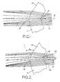
- the diffusion cover partly illustrated therein is a conventional diffusion cover for a motor vehicle headlamp and is moulded from glass so as to comprise upper and lower mutually inclined translucent cover portions 10 and 11 which are integrally joined together to define therebetween a peak line or ridge 12 on an outer surface of the cover and a corresponding trough 13 on the inner surface of the cover.
- the inner and outer surfaces of each cover portion 10, 11 are substantially parallel.
- the outer surface of each cover portion 10, 11 is unpatterned whereas the inner surface thereof, in accordance with conventional practice, is provided with a lensing pattern thereon to reduce the required light distribution or diffusion to achieve the required illumination of the road.
- both the ridge 12 and the trough 13 are radiussed. This has the result of defining a concavo-convex lens at the location where the cover portions 10 and 11 join. As a result of this, a vertical spread of light is produced. As illustrated in Fig.
- a parallel beam of light rays 14 emanating from a reflector of the headlight which is incident upon the inner surface of the diffusion cover in the region of the trough 13 is vertically spread so that some of the light rays, upon emerging from the outer surface of the diffusion cover are projected upwardly rather than downwardly as desired.
- This causes glare problems to oncoming drivers and means that it is difficult, if not impossible, for a motor vehicle headlamp fitted with such a diffusion cover to satisfy the stringent ridge 12.
- the diffusion cover illustrated therein is in accordance with an example of the present invention.
- the diffusion cover comprises upper and lower mutually inclined, translucent cover portions 110 and 111 which are integrally joined together to define therebetween a ridge 112 on an outer surface of the cover and a trough 113 on the inner surface of the cover.
- the diffusion cover is moulded with the trough 113 higher than the ridge 112 so that the horizontal median plane 16 of the trough 113 lies a distance D1 above the horizontal median plane 117 of the ridge 112.
- each of the upper and lower cover portions 110 and 113 have inner and outer surfaces which are generally parallel and spaced apart by a distance D2 in the case of the upper cover portion 110 and D3 in the case of the lower cover portion 111. D3 is greater than D2.
- the radius of curvature of the ridge 112 is R1 whilst the radius of curvature of the trough 113 is R2.
- the inner surface of the majority of the upper cover portion 110 is defined by a surface having an arcuate section of radius R3.
- the majority of the inner surface of the lower cover portion 111 is of arcuate section with radius R4.
- the remainder of the inner surface of the upper cover portion 110 i.e. that region thereof between the arcuate portion of radius R3 and the trough 113, is concave and is of arcuate cross-section of radius R5.
- the centre of the arc of radius R5 is disposed at a distance D4 from a perpendicular to the front surface of the cover portion 110, said perpendicular lying at a distance D5 from the horizontal median plane 117 of the ridge 112.
- the region of the inner surface of the lower cover portion 111 lying between the arcuate portion of radius R4 and the trough 113 is of convex form with an arcuate cross-section of radius R6.
- the centre of the arc of radius R6 is spaced a distance D6 from a perpendicular to the front surface of the lower cover portion 111, said perpendicular lying a distance D7 from the horizontal median plane 117 of the ridge 112.
- the outer surface of the upper cover portion 110 is radiussed in a like manner to the radiussing of the majority of the inner surface thereof so that it lies parallel therewith.
- the outer surface of the lower cover portion 111 is similarly radiussed with respect to the radiussing of the majority of the inner surface thereof at R4.
- the diffusion cover is surrounded by a peripheral flange 120 by which it is secured by means of an adhesive/sealant (not shown) to a peripheral flange 121 of a motor vehicle headlamp reflector 122.
- the reflector 122 has an internal paraboloidal reflective surface 123 having its focus at 124.
- An opening 125 is provided in the rear of the reflector 122 for receiving the body of a bulb (not shown) having a filament which is disposed so that it passes through the focus 124.
- the height of the diffusion cover not including the peripheral flange 120 is H (see Fig. 4); the horizontal median plane 117 of the trough 112 passes through the focus 124 and the focal axis of the reflective surface 123 lies in the median plane 117.
- Such an arrangement gives prism angles of 2 degrees and 6 degrees at the top and bottom of the concave region and prism angles of 6 degrees and 1 degree at the top and bottom of the convex region.
- Such an arrangement gives prism angles of 2.5 degrees and 9 degrees at the top and bottom of the concave region and 2.5 degrees and 18 degrees at the top and bottom of the convex region.
Landscapes
- Engineering & Computer Science (AREA)
- General Engineering & Computer Science (AREA)
- Non-Portable Lighting Devices Or Systems Thereof (AREA)
- Securing Globes, Refractors, Reflectors Or The Like (AREA)
Claims (4)
Applications Claiming Priority (2)
| Application Number | Priority Date | Filing Date | Title |
|---|---|---|---|
| GB8224035 | 1982-08-20 | ||
| GB8224035 | 1982-08-20 |
Publications (2)
| Publication Number | Publication Date |
|---|---|
| EP0103374A1 EP0103374A1 (de) | 1984-03-21 |
| EP0103374B1 true EP0103374B1 (de) | 1987-05-06 |
Family
ID=10532438
Family Applications (1)
| Application Number | Title | Priority Date | Filing Date |
|---|---|---|---|
| EP83304167A Expired EP0103374B1 (de) | 1982-08-20 | 1983-07-19 | Streuende Abdeckung für Kraftfahrzeugscheinwerfer |
Country Status (7)
| Country | Link |
|---|---|
| US (1) | US4520434A (de) |
| EP (1) | EP0103374B1 (de) |
| JP (1) | JPS5951402A (de) |
| AU (1) | AU560014B2 (de) |
| BR (1) | BR8304370A (de) |
| DE (1) | DE3371402D1 (de) |
| YU (1) | YU43833B (de) |
Families Citing this family (11)
| Publication number | Priority date | Publication date | Assignee | Title |
|---|---|---|---|---|
| JPS59138051A (ja) * | 1983-01-27 | 1984-08-08 | トヨタ自動車株式会社 | ランプ構造 |
| JPS60110902U (ja) * | 1983-12-28 | 1985-07-27 | 市光工業株式会社 | 自動車用前照灯 |
| JPS60183301U (ja) * | 1984-05-11 | 1985-12-05 | 市光工業株式会社 | 前照灯用レンズ |
| JPS61172403U (de) * | 1985-04-17 | 1986-10-27 | ||
| JPS61174101U (de) * | 1985-04-19 | 1986-10-29 | ||
| EP0221416B1 (de) * | 1985-11-07 | 1995-09-27 | Robert Bosch Gmbh | Scheinwerfer für Abblendlicht oder Nebellicht von Kraftfahrzeugen |
| US5117335A (en) * | 1989-12-28 | 1992-05-26 | Koito Manufacturing Co., Ltd. | Headlight for vehicle |
| JPH0817044B2 (ja) * | 1989-12-28 | 1996-02-21 | 株式会社小糸製作所 | 車輌用前照灯 |
| US6462479B1 (en) * | 2001-01-19 | 2002-10-08 | John T. Griffin | Vehicle headlamp system |
| US20020181244A1 (en) * | 2001-01-19 | 2002-12-05 | Griffin John T. | Vehicle headlamp system |
| CN113212294B (zh) * | 2021-03-19 | 2023-01-31 | 太原理工大学 | 一种汽车远光灯照射范围智能调节装置 |
Family Cites Families (4)
| Publication number | Priority date | Publication date | Assignee | Title |
|---|---|---|---|---|
| DE1220355B (de) * | 1964-08-07 | 1966-07-07 | Westfaelische Metall Ind K G | Eine Kammkante aufweisende Streuscheibe fuer Kraftfahrzeugscheinwerfer |
| FR1518841A (fr) * | 1967-02-13 | 1968-03-29 | Peugeot | Projecteur |
| US4446511A (en) * | 1980-03-14 | 1984-05-01 | General Electric Company | Automotive lamp unit |
| JPS57145201A (en) * | 1981-03-05 | 1982-09-08 | Koito Mfg Co Ltd | Head light lens for vehicle |
-
1983
- 1983-07-19 EP EP83304167A patent/EP0103374B1/de not_active Expired
- 1983-07-19 DE DE8383304167T patent/DE3371402D1/de not_active Expired
- 1983-07-28 US US06/518,107 patent/US4520434A/en not_active Expired - Fee Related
- 1983-08-08 AU AU17685/83A patent/AU560014B2/en not_active Ceased
- 1983-08-15 BR BR8304370A patent/BR8304370A/pt unknown
- 1983-08-17 YU YU1709/83A patent/YU43833B/xx unknown
- 1983-08-19 JP JP58150393A patent/JPS5951402A/ja active Pending
Also Published As
| Publication number | Publication date |
|---|---|
| DE3371402D1 (en) | 1987-06-11 |
| EP0103374A1 (de) | 1984-03-21 |
| BR8304370A (pt) | 1984-04-24 |
| US4520434A (en) | 1985-05-28 |
| JPS5951402A (ja) | 1984-03-24 |
| YU43833B (en) | 1989-12-31 |
| YU170983A (en) | 1986-06-30 |
| AU1768583A (en) | 1984-02-23 |
| AU560014B2 (en) | 1987-03-26 |
Similar Documents
| Publication | Publication Date | Title |
|---|---|---|
| US3492474A (en) | Reflector with compound curvature reflecting surface | |
| US5967647A (en) | Headlight for a vehicle, especially a motor vehicle | |
| US8070337B2 (en) | Vehicle lamp | |
| US6416210B1 (en) | Headlamp for a vehicle | |
| US20080253141A1 (en) | Lamp unit for vehicle | |
| US4945454A (en) | Reflector for dimmed or dimmable motor vehicle headlights | |
| JP2003123519A (ja) | プロジェクタ型ヘッドランプ | |
| EP0103374B1 (de) | Streuende Abdeckung für Kraftfahrzeugscheinwerfer | |
| JP2736726B2 (ja) | 車輌用前照灯 | |
| JPS58145002A (ja) | ランプ反射器 | |
| JPH08339704A (ja) | 車両用灯具装置 | |
| JPH0256801A (ja) | 自動車用前照灯 | |
| EP0432918B1 (de) | Fahrzeugscheinwerfer | |
| ES2587134T3 (es) | Faro del género elíptico para vehículo automóvil | |
| EP0106616A1 (de) | Scheinwerfer für Strassenfahrzeuge | |
| US4520433A (en) | Motor vehicle headlamp | |
| JPH02297801A (ja) | ランプ用反射鏡及びヘッドライトユニット | |
| JPH0250561B2 (de) | ||
| JPH0337242B2 (de) | ||
| EP0096785A1 (de) | Abgestutzter Fahrzeugscheinwerfer | |
| EP0971166A2 (de) | Kraftfahrzeugsleuchte mit einer mehrteiligen Fresnellinse | |
| JPH09102203A (ja) | 車両用灯具装置 | |
| JPH09306220A (ja) | 車両用灯具のリフレクタ | |
| JPS6355161B2 (de) | ||
| JPH0721801A (ja) | 車両用前照灯装置 |
Legal Events
| Date | Code | Title | Description |
|---|---|---|---|
| PUAI | Public reference made under article 153(3) epc to a published international application that has entered the european phase |
Free format text: ORIGINAL CODE: 0009012 |
|
| AK | Designated contracting states |
Designated state(s): DE FR GB IT |
|
| 17P | Request for examination filed |
Effective date: 19840917 |
|
| GRAA | (expected) grant |
Free format text: ORIGINAL CODE: 0009210 |
|
| ITF | It: translation for a ep patent filed | ||
| AK | Designated contracting states |
Kind code of ref document: B1 Designated state(s): DE FR GB IT |
|
| REF | Corresponds to: |
Ref document number: 3371402 Country of ref document: DE Date of ref document: 19870611 |
|
| ET | Fr: translation filed | ||
| PLBE | No opposition filed within time limit |
Free format text: ORIGINAL CODE: 0009261 |
|
| STAA | Information on the status of an ep patent application or granted ep patent |
Free format text: STATUS: NO OPPOSITION FILED WITHIN TIME LIMIT |
|
| 26N | No opposition filed | ||
| REG | Reference to a national code |
Ref country code: GB Ref legal event code: 732 |
|
| PGFP | Annual fee paid to national office [announced via postgrant information from national office to epo] |
Ref country code: FR Payment date: 19890712 Year of fee payment: 7 |
|
| ITTA | It: last paid annual fee | ||
| PGFP | Annual fee paid to national office [announced via postgrant information from national office to epo] |
Ref country code: GB Payment date: 19890731 Year of fee payment: 7 |
|
| PGFP | Annual fee paid to national office [announced via postgrant information from national office to epo] |
Ref country code: DE Payment date: 19890831 Year of fee payment: 7 |
|
| PG25 | Lapsed in a contracting state [announced via postgrant information from national office to epo] |
Ref country code: GB Effective date: 19900719 |
|
| GBPC | Gb: european patent ceased through non-payment of renewal fee | ||
| PG25 | Lapsed in a contracting state [announced via postgrant information from national office to epo] |
Ref country code: FR Effective date: 19910329 |
|
| PG25 | Lapsed in a contracting state [announced via postgrant information from national office to epo] |
Ref country code: DE Effective date: 19910403 |
|
| REG | Reference to a national code |
Ref country code: FR Ref legal event code: ST |