EP0103340B1 - Vorrichtung und Verfahren zum Biegen von gewellten Platten - Google Patents
Vorrichtung und Verfahren zum Biegen von gewellten Platten Download PDFInfo
- Publication number
- EP0103340B1 EP0103340B1 EP83201304A EP83201304A EP0103340B1 EP 0103340 B1 EP0103340 B1 EP 0103340B1 EP 83201304 A EP83201304 A EP 83201304A EP 83201304 A EP83201304 A EP 83201304A EP 0103340 B1 EP0103340 B1 EP 0103340B1
- Authority
- EP
- European Patent Office
- Prior art keywords
- press beam
- recesses
- valleys
- plate
- press
- Prior art date
- Legal status (The legal status is an assumption and is not a legal conclusion. Google has not performed a legal analysis and makes no representation as to the accuracy of the status listed.)
- Expired
Links
- 238000005452 bending Methods 0.000 title claims abstract description 33
- 238000000034 method Methods 0.000 title claims abstract description 9
- 230000006835 compression Effects 0.000 claims description 6
- 238000007906 compression Methods 0.000 claims description 6
- 230000013011 mating Effects 0.000 claims 1
- 238000010276 construction Methods 0.000 description 2
- 230000005540 biological transmission Effects 0.000 description 1
- 238000005253 cladding Methods 0.000 description 1
- 239000000463 material Substances 0.000 description 1
- 239000002184 metal Substances 0.000 description 1
- 229920003023 plastic Polymers 0.000 description 1
- 239000004033 plastic Substances 0.000 description 1
Images
Classifications
-
- B—PERFORMING OPERATIONS; TRANSPORTING
- B21—MECHANICAL METAL-WORKING WITHOUT ESSENTIALLY REMOVING MATERIAL; PUNCHING METAL
- B21D—WORKING OR PROCESSING OF SHEET METAL OR METAL TUBES, RODS OR PROFILES WITHOUT ESSENTIALLY REMOVING MATERIAL; PUNCHING METAL
- B21D11/00—Bending not restricted to forms of material mentioned in only one of groups B21D5/00, B21D7/00, B21D9/00; Bending not provided for in groups B21D5/00 - B21D9/00; Twisting
- B21D11/08—Bending by altering the thickness of part of the cross-section of the work
-
- B—PERFORMING OPERATIONS; TRANSPORTING
- B21—MECHANICAL METAL-WORKING WITHOUT ESSENTIALLY REMOVING MATERIAL; PUNCHING METAL
- B21D—WORKING OR PROCESSING OF SHEET METAL OR METAL TUBES, RODS OR PROFILES WITHOUT ESSENTIALLY REMOVING MATERIAL; PUNCHING METAL
- B21D11/00—Bending not restricted to forms of material mentioned in only one of groups B21D5/00, B21D7/00, B21D9/00; Bending not provided for in groups B21D5/00 - B21D9/00; Twisting
- B21D11/20—Bending sheet metal, not otherwise provided for
- B21D11/206—Curving corrugated sheets
-
- B—PERFORMING OPERATIONS; TRANSPORTING
- B21—MECHANICAL METAL-WORKING WITHOUT ESSENTIALLY REMOVING MATERIAL; PUNCHING METAL
- B21D—WORKING OR PROCESSING OF SHEET METAL OR METAL TUBES, RODS OR PROFILES WITHOUT ESSENTIALLY REMOVING MATERIAL; PUNCHING METAL
- B21D13/00—Corrugating sheet metal, rods or profiles; Bending sheet metal, rods or profiles into wave form
- B21D13/02—Corrugating sheet metal, rods or profiles; Bending sheet metal, rods or profiles into wave form by pressing
Definitions
- the invention relates to a device for bending plates having a corrugated profile, comprising a pair of press beams, which are positioned parallel one relative to the other and are mounted to be moved towards and away from each other in a transversal direction with regard to the longitudinal extension of said beams, a first or lower press beam having at its upper edge a series of alternating recesses and extensions which correspond with the exterior valley profile and interior crest profile respectively of the plate to be bent, while a second or upper press beam has a series of alternating extensions and recesses which correspond with the interior valley profile and the exterior crest profile respectively, and in which on the sidewalls of the recesses in said upper press beam - adjacent the junction of said sidewalls and the bottoms of said recesses - a protuberance is provided adapted to amply engage into a corresponding cut-out in the sidewall of the underlying extension of the lower press beam when the two press beams are brought together, said lower press beam having a ledge portion at its upper face extending in the longitudinal direction of said
- the invention relates to the bending of corrugated sheets, with which the alternating valleys and crests are trapezoide, like a metal coffer dam.
- Such plates which are often referred to as plates having a coffer dam profile, are used on a large scale for roofing and cladding purposes.
- WO-A-8000932 discloses a device of the kind above referred to for bending such plates about an axis extending transversally to the valleys and crests, in which by means of said ledge portion a series of aligned ribs, extending transversally to the crests and valleys, is impressed from beneath, i.e. towards the crests, into the bottoms of the valleys, while the protruberances on the side faces of the recesses in the operative upper face impress corresponding bulges into the sidewalls of the valleys of the plate in the region adjacent the ends of the ribs in the bottom of said valleys. In such a way in fact a slight fold (of e.g.
- the ledge portion is movably mounted between an inoperative position, in which said ledge portion has its operative upper edge sunk into a groove extending across all of said recesses of the lower press beam - consists of two sections which are movable one relative to the other, said sections comprising an upper section facing towards the upper press beam and containing the raised portions and recesses of the lower press beam, as well as a lower section facing away from said upper press beam and containing said ledge portion - and an operative position, in which the said ledge portion has its operative upper edge projecting through said groove upwards beyond the bottoms of the recesses in the lower press beam, pretensioned compression spring means being provided between said lower press beam and said ledge portion tending to urge said ledge portion in said inoperative position.
- a device has been obtained, with which the bending procedure is taking place in two distinct stages, i.e. a first stage, in which the bulges are formed, and a second stage, in which the ribs are formed.
- the first stage the ledge portion is taking its inoperative retracted position, so that the plate to be bent is then smoothly bearing on the upper faces, bottoms and sidewalls of the projections and recesses of the lower press beam.
- all of the bulges will obtain the same regular shape and a symmetrical position relative to the ribs formed in the second stage.
- the invention also relates to a method for bending a corrugated plate about an axis extending transversally to the valleys and crests respectively according to the preamble of claim 6.
- the method according to the invention is characterized in that in the first stage, in which the plate as seen in the longitudinal direction of the crests and valleys is supported through a length which is a multiple of the width of the ribs to be formed, the bulges are pressed only, while the ribs are formed in the subsequent stage.
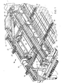
- the portion of the bending device shown in Fig. 1 has a frame 21 with a horizontal guide rail 22, 23 extending on either side of it.
- 25 designates a carriage which is mounted on said frame for a reciprocating movement in the direction of the arrow.
- the carriage 25 is provided with rollers 24, which are guided by the rails 22 and 23 respectively.
- the frame 21 further comprises two beams 26 and 27, mounted between and parallel to the rails 22 and 23. In each of said beams 26 and 27 a toothed rack 28 and 29 respectively is provided. Between the rails 22, 23 and the beams 26, 27 a number of transverse rollers 30 are mounted for free rotation.
- the rollers 30 constitute a supporting surface for the plate P to be bent, which plate is indicated with dash-dotted lines in Fig. 1.
- the carriage 25 may be displaced on the frame 21 by means of two gear wheels 32 and 33, mounted on said carriage and interconnected by a shaft 31. Each of said gear wheels cooperates with a toothed rack 26, 27.
- the gear wheels 32 and 33 may be driven by a motor 36 via a transmission 34 and a gear 35 engaging the gear wheel 32.
- the motor 36 may be controlled from a control panel 37.
- the carriage 25 is provided with a device for clamping and holding the end of the plate P faced towards the carriage.
- This device comprises a transversely extending clamping beam 38 and a number of clamping fingers 39, which may be moved relative to the clamping beam in the direction of the arrow so as to clamp the plate to be bent in the crest areas.
- the clamping beam 38 is making part of a frame 40, which is guided for an up and down movement along guide rods 41 provided on either side of the carriage. By means of said frame 40 the clamping beam 38 can be adjusted to the level of the crests of the plate P.
- a shaft 42 is journalled in the sidewalls of the carriage 25, which shaft carries two toothed wheels 43, which engage toothed racks 44 carried by the frame 40.
- Fig. 1 shows the carriage 25 in its retracted position with respect to the proper bending device, indicated in Fig. 2.
- a plate to be bent may be laid on the supporting rollers 30 and clamped between the clamping beams 38 and the clamping fingers 39. Thereupon the feeding of the plate P towards the bending device may be started.
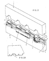
- Fig. 2 only shows the two press beams 1 and 2 of the proper bending device.
- This bending device further comprises a frame, which is to be considered as an extension of the frame 21 shown in Fig. 1 and which supports the two press beams 1 and 2 so, that the latter may be moved one with respect to the other in the direction of arrow I.
- the bending device further comprises the necessary driving equipment for moving and adjusting of the press beams.
- these parts of the bending device have no direct relation to the present invention and may be of a well-known construction, they will not be described in detail. For the sake of simplicity reference may be made to the well-known construction disclosed in British patent specification 1.573.849.
- the upper press beam 1 is constituted by one integral piece.
- This press beam has, on its face directed towards the lower press beam 2, a number of alternating raised portions and recesses 1a and 1b respectively, which correspond with the valleys and crests of the corrugated plate P.
- the lower press beam 2 has at its upper face a number of alternating raised portions and recesses 2a and 2b respectively, which correspond with the recesses and raised portions 1b and 1a respectively of the upper press beam 1.
- the lower press beam 2 comprises two sections 2' and 2", placed one on top of the other, the upper section 2" of which comprising the raised portions and recesses 2a and 2b respectively.
- the press beam section 2" is composed of two strips 4, which bound a slot 5 extending along the entire press beam length and are interconnected by the raised portions 2a which have been formed as separate bridge pieces. As seen in Fig. 2, the strips 4 are provided with grooves 6, within which the fastening means for the raised portions or bridge pieces 2a may be slidingly adjusted so that the press beam section 2' may be adjusted to various profiles of the corrugated plate to be bent by changing and/or sliding of the raised portions or bridge pieces 2a.
- the press beam section 2" is supported by the lower press beam section 2' by means of compression springs 7.
- Holding strips 8 are provided on either side of the lower press beam section 2', which strips have an upper edge which is bent inwards and engages an outwardly extended flange of the respective strips 4 of the upper press beam section 2". In this way the holding strips 8 keep the compression springs 7 in a prestressed condition.
- a ledge-shaped punch 9 extends across the entire length of the press beams and is mounted in a groove in the upper face of the lower press beam section 2'.
- the upper press beam 1 is provided with protuberances 11 in the junction areas between the bottoms at adjacent sidewalls of the recesses 1 b. When the two press beams are closed, these protuberances may amply engage into corresponding cut-outs 12 in the sidewalls of the raised portions or bridge pieces 2a of the lower press beam.
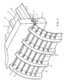
- the plate P to be bent is fed stepwise, e.g. in the direction of arrow II on the rollers 30 in Fig. 1, between the press beams 1 and 2.
- stepwise feeding may be automatic according to a program which is making part of the control circuitry contained in the control panel 37.
- the increments of the stepwise feeding, as well as the stroke of the punch are constituting variable factors, by means of which the size of the bending radius may be determined.
- Fig. 3 represents the situation in which the plate P, having a usual so-called coffer dam profile, has already been subjected to six bending steps, while the two press beams 1 and 2 are in the process of carrying out the seventh bending step.
- the closing movement of the two press beams 1 and 2 may be effected in various members.
- the lower press beam 2 could be stationary, in which case only the upper press beam would be movable.
- the upper press beam could be stationary and the lower press beam be movably mounted.
- the bending angle in each individual bending step could be adjusted by adjusting the depth of the ribs 15, which could be realized by selecting the pressure, at which the two press beams are brought together.
Landscapes
- Engineering & Computer Science (AREA)
- Mechanical Engineering (AREA)
- Bending Of Plates, Rods, And Pipes (AREA)
- Shaping Of Tube Ends By Bending Or Straightening (AREA)
- Wire Processing (AREA)
Claims (4)
Priority Applications (1)
| Application Number | Priority Date | Filing Date | Title |
|---|---|---|---|
| AT83201304T ATE28418T1 (de) | 1982-09-09 | 1983-09-09 | Vorrichtung und verfahren zum biegen von gewellten platten. |
Applications Claiming Priority (2)
| Application Number | Priority Date | Filing Date | Title |
|---|---|---|---|
| NL8203509 | 1982-09-09 | ||
| NL8203509A NL8203509A (nl) | 1982-09-09 | 1982-09-09 | Inrichting en werkwijze voor het buigen van golfplaten. |
Publications (3)
| Publication Number | Publication Date |
|---|---|
| EP0103340A2 EP0103340A2 (de) | 1984-03-21 |
| EP0103340A3 EP0103340A3 (en) | 1984-04-25 |
| EP0103340B1 true EP0103340B1 (de) | 1987-07-22 |
Family
ID=19840248
Family Applications (1)
| Application Number | Title | Priority Date | Filing Date |
|---|---|---|---|
| EP83201304A Expired EP0103340B1 (de) | 1982-09-09 | 1983-09-09 | Vorrichtung und Verfahren zum Biegen von gewellten Platten |
Country Status (7)
| Country | Link |
|---|---|
| US (1) | US4603572A (de) |
| EP (1) | EP0103340B1 (de) |
| AT (1) | ATE28418T1 (de) |
| AU (1) | AU568095B2 (de) |
| DE (1) | DE3372589D1 (de) |
| NL (1) | NL8203509A (de) |
| WO (1) | WO1984000907A1 (de) |
Families Citing this family (10)
| Publication number | Priority date | Publication date | Assignee | Title |
|---|---|---|---|---|
| SE445309B (sv) * | 1983-12-16 | 1986-06-16 | Graenges Aluminium Ab | Forfarande for bockning av profilerad plat samt verktyg for utforande av forfarandet |
| SE459481B (sv) * | 1987-11-03 | 1989-07-10 | Anita Elisabeth Mattsson Med F | Metod och anordning foer bockning av korrugerad plaat |
| US5085623A (en) * | 1990-02-06 | 1992-02-04 | Union Camp Corporation | Bar scoring apparatus |
| US5303572A (en) * | 1992-05-07 | 1994-04-19 | Knudson Gary Art | Panel bending apparatus and method |
| US6354130B1 (en) * | 2000-09-22 | 2002-03-12 | Cathy D. Santa Cruz | Method for bending a corrugated sheet |
| JP4581579B2 (ja) * | 2004-09-14 | 2010-11-17 | セイコーエプソン株式会社 | 金属基板の加工方法及び液体噴射ヘッドの製造方法 |
| US7313941B1 (en) * | 2005-12-02 | 2008-01-01 | Sen-Jung Chuang | Corrugated sheet member bending machine |
| BRPI0818695A2 (pt) * | 2007-10-01 | 2015-09-01 | Inventio Ag | Dispositivo de embutição profunda |
| FR3020769B1 (fr) * | 2014-05-06 | 2017-01-06 | Gaztransport Et Technigaz | Dispositif et procede de pliage pour former une ondulation dans une tole metallique |
| PL448462A1 (pl) * | 2024-04-30 | 2025-11-03 | Jędrysa Renata Firma Produkcyjno-Handlowa Mettom | Blacha profilowana i sposób wytwarzania takiej blachy profilowanej |
Family Cites Families (10)
| Publication number | Priority date | Publication date | Assignee | Title |
|---|---|---|---|---|
| CA632626A (en) * | 1961-12-12 | Sealed Power Corporation | Punch press | |
| US1556611A (en) * | 1922-11-21 | 1925-10-13 | Bliss E W Co | Drawing press |
| US2033667A (en) * | 1933-04-03 | 1936-03-10 | Midland Steel Prod Co | Apparatus for forming elongated corrugated poles |
| FR1390329A (fr) * | 1964-01-13 | 1965-02-26 | Technigaz Soc | Machine automatique à plier pour la réalisation de deux familles sécantes d'ondulations parallèles |
| DE1552031A1 (de) * | 1966-04-20 | 1969-12-18 | Mannesmann Ag | Verfahren zum Biegen von Trapezblechen und Maschine zur Durchfuehrung des Verfahrens |
| FR1601215A (de) * | 1968-12-31 | 1970-08-10 | ||
| AU504467B2 (en) * | 1976-06-11 | 1979-10-18 | Harold Rex Jury And Heather Joy Jury | Bending corrugated sheetmetal |
| GB1573849A (en) * | 1977-06-16 | 1980-08-28 | Korstraesk Mek G Naeslund | Method and device for bending corrugated sheet and a bent corrugated sheet |
| SE7811538L (sv) * | 1978-11-08 | 1980-05-09 | Groko Maskin Ab | Forfarande och anordning for bockning av profilerad plat |
| DE3037590C2 (de) * | 1980-10-04 | 1985-05-30 | Vereinigte Aluminium-Werke AG, 1000 Berlin und 5300 Bonn | Vorrichtung zum Biegen von gewellten oder profilierten Blechen |
-
1982
- 1982-09-09 NL NL8203509A patent/NL8203509A/nl not_active Application Discontinuation
-
1983
- 1983-09-09 AU AU20380/83A patent/AU568095B2/en not_active Ceased
- 1983-09-09 DE DE8383201304T patent/DE3372589D1/de not_active Expired
- 1983-09-09 AT AT83201304T patent/ATE28418T1/de not_active IP Right Cessation
- 1983-09-09 EP EP83201304A patent/EP0103340B1/de not_active Expired
- 1983-09-09 US US06/610,644 patent/US4603572A/en not_active Expired - Fee Related
- 1983-09-09 WO PCT/NL1983/000035 patent/WO1984000907A1/en not_active Ceased
Also Published As
| Publication number | Publication date |
|---|---|
| EP0103340A3 (en) | 1984-04-25 |
| WO1984000907A1 (en) | 1984-03-15 |
| NL8203509A (nl) | 1984-04-02 |
| EP0103340A2 (de) | 1984-03-21 |
| ATE28418T1 (de) | 1987-08-15 |
| DE3372589D1 (en) | 1987-08-27 |
| AU2038083A (en) | 1984-03-29 |
| AU568095B2 (en) | 1987-12-17 |
| US4603572A (en) | 1986-08-05 |
Similar Documents
| Publication | Publication Date | Title |
|---|---|---|
| EP0103340B1 (de) | Vorrichtung und Verfahren zum Biegen von gewellten Platten | |
| US4250728A (en) | Apparatus and method for forming steps in profiled sheets of material | |
| US4574553A (en) | Spacer frame and method for bending hollow shaped bar portions to form spacer frames for insulating glass | |
| DE2848669C2 (de) | ||
| US4380573A (en) | Method and device for bending section-sheet, plate, strip and like material | |
| US4347726A (en) | Method and device for bending sheet-metal sections | |
| US4658624A (en) | Bending Machines | |
| DE69403933T2 (de) | Vorrichtung zum Führen und Fördern von mindestens zwei angedockenden Blechen, und Schweissanlage mit solcher Vorrichtung | |
| US4449388A (en) | Method of bending shaped metal sheet and apparatus for carrying out the method | |
| US3291360A (en) | Machine for the manufacture of beams and the like | |
| CA1216504A (en) | Device and method for bending corrugated plates | |
| GB1573849A (en) | Method and device for bending corrugated sheet and a bent corrugated sheet | |
| US5243844A (en) | Process for producing curved sections in hollow profile strips | |
| ATE8746T1 (de) | Verfahren und vorrichtung zum biegen von gewellten oder profilierten blechen. | |
| JPH0429446B2 (de) | ||
| SU1761362A1 (ru) | Способ прокатки изделий переменного профил и устройство дл его осуществлени | |
| US2534523A (en) | Apparatus for shaping structural glass | |
| SU1442414A1 (ru) | Устройство дл резки обрезиненной ткани | |
| US6129655A (en) | Method of folding and shaping sheet, and apparatus for folding and shaping sheet | |
| CA1083023A (en) | Method and device for bending section-sheet, plate, strip and like material | |
| SE8306988D0 (sv) | Forfarande for bockning av en profilerad plat och verktyg for utforande av forfarandet | |
| SU905077A2 (ru) | Устройство дл изготовлени решетчатого заполнител пустотелых щитов | |
| US1739249A (en) | Machine for folding sheet metal | |
| SU475271A1 (ru) | Устройство дл укладки на поддон планок лицевого покрыти паркетных досок | |
| KR870000618B1 (ko) | 성형금속판의 절곡장치 |
Legal Events
| Date | Code | Title | Description |
|---|---|---|---|
| PUAI | Public reference made under article 153(3) epc to a published international application that has entered the european phase |
Free format text: ORIGINAL CODE: 0009012 |
|
| PUAL | Search report despatched |
Free format text: ORIGINAL CODE: 0009013 |
|
| AK | Designated contracting states |
Designated state(s): AT BE CH DE FR GB IT LI NL SE |
|
| AK | Designated contracting states |
Designated state(s): AT BE CH DE FR GB IT LI NL SE |
|
| 17P | Request for examination filed |
Effective date: 19841031 |
|
| R17P | Request for examination filed (corrected) |
Effective date: 19841024 |
|
| GRAA | (expected) grant |
Free format text: ORIGINAL CODE: 0009210 |
|
| AK | Designated contracting states |
Kind code of ref document: B1 Designated state(s): AT BE CH DE FR GB IT LI NL SE |
|
| REF | Corresponds to: |
Ref document number: 28418 Country of ref document: AT Date of ref document: 19870815 Kind code of ref document: T |
|
| REF | Corresponds to: |
Ref document number: 3372589 Country of ref document: DE Date of ref document: 19870827 |
|
| ITF | It: translation for a ep patent filed | ||
| ET | Fr: translation filed | ||
| PLBI | Opposition filed |
Free format text: ORIGINAL CODE: 0009260 |
|
| 26 | Opposition filed |
Opponent name: GROKO MASKIN AB Effective date: 19880421 |
|
| NLR1 | Nl: opposition has been filed with the epo |
Opponent name: GROKO MASKIN AB |
|
| PLBN | Opposition rejected |
Free format text: ORIGINAL CODE: 0009273 |
|
| STAA | Information on the status of an ep patent application or granted ep patent |
Free format text: STATUS: OPPOSITION REJECTED |
|
| 27O | Opposition rejected |
Effective date: 19891013 |
|
| NLR2 | Nl: decision of opposition | ||
| ITTA | It: last paid annual fee | ||
| PGFP | Annual fee paid to national office [announced via postgrant information from national office to epo] |
Ref country code: SE Payment date: 19920903 Year of fee payment: 10 |
|
| PGFP | Annual fee paid to national office [announced via postgrant information from national office to epo] |
Ref country code: GB Payment date: 19920908 Year of fee payment: 10 |
|
| PGFP | Annual fee paid to national office [announced via postgrant information from national office to epo] |
Ref country code: DE Payment date: 19920914 Year of fee payment: 10 |
|
| PGFP | Annual fee paid to national office [announced via postgrant information from national office to epo] |
Ref country code: BE Payment date: 19920917 Year of fee payment: 10 |
|
| PGFP | Annual fee paid to national office [announced via postgrant information from national office to epo] |
Ref country code: AT Payment date: 19920923 Year of fee payment: 10 |
|
| PGFP | Annual fee paid to national office [announced via postgrant information from national office to epo] |
Ref country code: FR Payment date: 19920929 Year of fee payment: 10 |
|
| PGFP | Annual fee paid to national office [announced via postgrant information from national office to epo] |
Ref country code: NL Payment date: 19920930 Year of fee payment: 10 |
|
| PGFP | Annual fee paid to national office [announced via postgrant information from national office to epo] |
Ref country code: CH Payment date: 19921222 Year of fee payment: 10 |
|
| PG25 | Lapsed in a contracting state [announced via postgrant information from national office to epo] |
Ref country code: GB Effective date: 19930909 Ref country code: AT Effective date: 19930909 |
|
| PG25 | Lapsed in a contracting state [announced via postgrant information from national office to epo] |
Ref country code: SE Effective date: 19930910 |
|
| PG25 | Lapsed in a contracting state [announced via postgrant information from national office to epo] |
Ref country code: LI Effective date: 19930930 Ref country code: CH Effective date: 19930930 Ref country code: BE Effective date: 19930930 |
|
| BERE | Be: lapsed |
Owner name: DUPRAL B.V. Effective date: 19930930 |
|
| PG25 | Lapsed in a contracting state [announced via postgrant information from national office to epo] |
Ref country code: NL Effective date: 19940401 |
|
| GBPC | Gb: european patent ceased through non-payment of renewal fee |
Effective date: 19930909 |
|
| NLV4 | Nl: lapsed or anulled due to non-payment of the annual fee | ||
| PG25 | Lapsed in a contracting state [announced via postgrant information from national office to epo] |
Ref country code: FR Free format text: LAPSE BECAUSE OF NON-PAYMENT OF DUE FEES Effective date: 19940531 |
|
| REG | Reference to a national code |
Ref country code: CH Ref legal event code: PL |
|
| PG25 | Lapsed in a contracting state [announced via postgrant information from national office to epo] |
Ref country code: DE Effective date: 19940601 |
|
| REG | Reference to a national code |
Ref country code: FR Ref legal event code: ST |
|
| EUG | Se: european patent has lapsed |
Ref document number: 83201304.9 Effective date: 19940410 |