EP0102798B1 - Serre-câble pour un connecteur électrique - Google Patents
Serre-câble pour un connecteur électrique Download PDFInfo
- Publication number
- EP0102798B1 EP0102798B1 EP83304824A EP83304824A EP0102798B1 EP 0102798 B1 EP0102798 B1 EP 0102798B1 EP 83304824 A EP83304824 A EP 83304824A EP 83304824 A EP83304824 A EP 83304824A EP 0102798 B1 EP0102798 B1 EP 0102798B1
- Authority
- EP
- European Patent Office
- Prior art keywords
- cable
- wall
- clamping
- walls
- clamp according
- Prior art date
- Legal status (The legal status is an assumption and is not a legal conclusion. Google has not performed a legal analysis and makes no representation as to the accuracy of the status listed.)
- Expired
Links
- 210000005069 ears Anatomy 0.000 claims description 3
- 230000007423 decrease Effects 0.000 claims 1
- 230000001419 dependent effect Effects 0.000 claims 1
- 230000014759 maintenance of location Effects 0.000 description 5
- 230000002093 peripheral effect Effects 0.000 description 2
- 238000005452 bending Methods 0.000 description 1
- 238000010276 construction Methods 0.000 description 1
- 230000006866 deterioration Effects 0.000 description 1
- 230000002708 enhancing effect Effects 0.000 description 1
- 210000000887 face Anatomy 0.000 description 1
- 238000010348 incorporation Methods 0.000 description 1
- 238000005304 joining Methods 0.000 description 1
- 238000004519 manufacturing process Methods 0.000 description 1
- 238000007567 mass-production technique Methods 0.000 description 1
- 239000000463 material Substances 0.000 description 1
- 238000000034 method Methods 0.000 description 1
- 238000000465 moulding Methods 0.000 description 1
- 229920003023 plastic Polymers 0.000 description 1
- 239000004033 plastic Substances 0.000 description 1
- 238000003825 pressing Methods 0.000 description 1
- 230000000750 progressive effect Effects 0.000 description 1
- 230000000452 restraining effect Effects 0.000 description 1
Images


Classifications
-
- H—ELECTRICITY
- H01—ELECTRIC ELEMENTS
- H01R—ELECTRICALLY-CONDUCTIVE CONNECTIONS; STRUCTURAL ASSOCIATIONS OF A PLURALITY OF MUTUALLY-INSULATED ELECTRICAL CONNECTING ELEMENTS; COUPLING DEVICES; CURRENT COLLECTORS
- H01R13/00—Details of coupling devices of the kinds covered by groups H01R12/70 or H01R24/00 - H01R33/00
- H01R13/58—Means for relieving strain on wire connection, e.g. cord grip, for avoiding loosening of connections between wires and terminals within a coupling device terminating a cable
- H01R13/582—Means for relieving strain on wire connection, e.g. cord grip, for avoiding loosening of connections between wires and terminals within a coupling device terminating a cable the cable being clamped between assembled parts of the housing
-
- H—ELECTRICITY
- H01—ELECTRIC ELEMENTS
- H01R—ELECTRICALLY-CONDUCTIVE CONNECTIONS; STRUCTURAL ASSOCIATIONS OF A PLURALITY OF MUTUALLY-INSULATED ELECTRICAL CONNECTING ELEMENTS; COUPLING DEVICES; CURRENT COLLECTORS
- H01R12/00—Structural associations of a plurality of mutually-insulated electrical connecting elements, specially adapted for printed circuits, e.g. printed circuit boards [PCB], flat or ribbon cables, or like generally planar structures, e.g. terminal strips, terminal blocks; Coupling devices specially adapted for printed circuits, flat or ribbon cables, or like generally planar structures; Terminals specially adapted for contact with, or insertion into, printed circuits, flat or ribbon cables, or like generally planar structures
- H01R12/70—Coupling devices
- H01R12/77—Coupling devices for flexible printed circuits, flat or ribbon cables or like structures
-
- H—ELECTRICITY
- H01—ELECTRIC ELEMENTS
- H01R—ELECTRICALLY-CONDUCTIVE CONNECTIONS; STRUCTURAL ASSOCIATIONS OF A PLURALITY OF MUTUALLY-INSULATED ELECTRICAL CONNECTING ELEMENTS; COUPLING DEVICES; CURRENT COLLECTORS
- H01R13/00—Details of coupling devices of the kinds covered by groups H01R12/70 or H01R24/00 - H01R33/00
- H01R13/46—Bases; Cases
- H01R13/502—Bases; Cases composed of different pieces
- H01R13/506—Bases; Cases composed of different pieces assembled by snap action of the parts
Definitions
- the invention relates to a cable clamp and particularly to a cable clamp which is suitable for incorporation with an electrical connector housing.
- Cable clamps are required for many cable terminations with electrical connectors to ensure that stress imposed on the cable is not transmitted to the termination and does not result in deterioration of the electrical connection.
- a known cable clamp described in GB Patent Specification 1551298 comprises first and second clamping members having first and second clamping walls respectively, locatable in laterally spaced, parallel relation in a cable receiving condition in which free ends of the walls engage respective axially spaced opposite sides of a cable located between them, cable engaging surface portions of the walls being progressively movable into overlapping relation to deform transversely and trap between them a portion of the cable in a clamping condition and means to secure the clamping members in the clamping condition.
- means are provided on the clamping members to urge the walls progressively together during such movement into gripping engagement with the trapped cable portion into the clamping condition.
- the walls may be relatively free to move apart or widely spaced during initial deformation of the cable avoiding excessive frictional drag on the cable and excessive closure forces.
- cam means are provided on the clamping members to urge the walls relatively together during final stages of movement to the clamping condition.
- the cable engaging surface portion is formed with cable gripping barbs further to enhance the cable retention force.
- the barbs have cable engaging edges facing the free end of the first wall enhancing the retention force in one direction, in practice usually to resist the cable being pulled away from the termination during movement of the cable clamp to the closed condition.
- the cable engaging surface portions terminate at the free ends of the first and second walls in an angular cable gripping edge and a curved sliding surface, respectively.
- a cable locating lug may also be provided to prevent the cable diverging from a right angle formed by engagement with the edge during closure together of the clamping members.
- the first clamping member includes a third clamping wall located laterally spaced from and generally parallel to the first wall, the first and third walls upstanding from a common base and the third wall being of less height than the first wall, the second wall being received between the first and third walls in the clamping condition.
- interengagable guide means are provided on the first and second clamping members to guide the clamping members together during movement from the cable receiving condition to the cable clamping condition with the second wall nearer to the first wall than to the third wall.
- the differential spacing of the walls also ensures sufficient clearance to enable cable to be drawn relatively freely across the third wall during movement of the clamp to a closed condition.
- the free end of the first wall is formed with an elongate, cable locating recess.
- the recess provides additional clearance from the locating lug to enable relatively narrow and thick cables to be accommodated in the recess. Relatively thin and wide cables overlap the longitudinal edge portions of the recess.
- the second clamping member may include a fourth wall extending in the same direction as the first wall and having a free end arranged to engage a cable adjacent a free end of the third wall remote from the second wall.
- the cam surface is formed by a pair of laterally spaced ears extending from the second wall towards the third wall and defining between them a cable receiving space, the abutment being constituted by a free end of the third wall.
- first and second clamping members are integrally joined respectively to cable receiving ends of base member and cover member of an electrical connector housing, means being provided on the base member to secure an electrical terminal assembly to the base member adjacent a side of the first wall remote from the third wall.
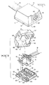
- the electrical connector comprises a housing including a base member 11 and a cover member 12 each moulded in one piece of plastics material and containing an electrical terminal assembly including a printed circuit board 13 from which upstand slotted barrel, wire receiving terminals 14 similar to those described in U.S. Patent No. 3,860,318 receiving wire stuffing caps 15 similar to those described in U.S. Patent No. 4,186,948.
- a telephone jack 16 similar to that described in U.S. Patent No. 4,231,628 is mounted on the printed circuit board adjacent a contact face of the housing with individual contacts electrically connected by the printed circuit board to individual wires 18 of a flat cable 19 terminated by the terminals 14.
- the base member 11 and cover member 12 incorporate at wire receiving ends first and second clamping members 21 and 22, respectively.
- the first clamping member includes first and third clamping walls 24 and 25, respectively, upstanding in spaced apart parallel relation from a base wall 26.
- Two series of supporting brackets 27, 27' are respectively provided along front and rear faces of respective walls and two supporting brackets 28 are provided on the front of the third clamping wall to each side of a cable engaging end 33.
- a cable engaging portion of the first wall is formed with cable gripping means comprising a plurality of barbs 29 having cable engaging edges 29' facing a free end 30 of the wall.
- Apertures 31 in the base wall enable the moulding of the barbs 29.
- the cable engaging surface of the first wall terminates in a cable gripping edge 33 at a cable engaging end 30 which is formed with an elongate cable locating recess 32.
- the second clamping member 22 includes second and fourth clamping walls 35 and 36 depending from a top wall 37 of the cover member.
- the second wall 35 depends perpendicularly from the top wall located in laterally spaced, parallel relation to the first wall 24 in the operative condition of the clamping members and terminates, at a free cable engaging end 39, in a curved sliding, cable engaging, surface 38.
- Cam members comprising laterally spaced ears 41 extend between the second and fourth walls and are provided with camming surfaces 42 towards a wire receiving end.
- Spaced supporting brackets 43 also extend between the second and fourth walls adjacent a cable receiving rebate 44 in the fourth wall.
- a pair of spaced apart cable locating lugs 45 extend between the top and second walls of the cover.
- a side wall 47 of the cover is formed at a contact end of the connector with an opening 46 and at free ends with a peripheral skirt 48 joining the fourth wall 36 at the contact end of the connector.
- Latching detents 49 and eyes 50 are provided on the interiors of the opposite sides of the skirt and at the junction of the fourth wall and the skirt on each side of the cable receiving opening 44.
- a release tool receiving cut out 57 is formed on the free end of the skirt on each side of the connector.
- the base member is formed with a side wall 53 upstanding and inset from the periphery of the base wall 26 to a provide peripheral cover locating seat 54.
- a portion 53' of the side wall projects to the contact face of the base member.
- Latching recesses 55 and catches 56 are provided on opposite external sides of the side wall 53 and on the third wall 25 which is coextensive with the side wall 53.
- Supporting ribs 58 extend in spaced parallel relation across the base wall 26 and a pair of locating bosses 59 upstand in spaced apart relation from the base wall adjacent the contact face.
- Terminal assembly retaining catches 60 extend inwardly from opposite free ends of the side wall 53 adjacent the first wall 24 for cooperation with a pair of resilient latches 61 which upstand from the base wall in spaced apart relation.
- the printed circuit board 13 is formed with boss-receiving apertures 63 and the telephone jack is formed on opposite sides with a vertically extending, cover locating, ribs 64.
- the terminal assembly is mounted in the base member by one end of the printed circuit board being received under the two catches 60 and the other end being subsequently received as a snap fit by the latches 61, the apertures 63 registering with the bosses 59.
- the individual wires 18 may be stuffed into the terminals 15 using the technique described in U.S. Patent No. 4,186,948 prior or subsequent to mounting the terminal assembly in the base member.
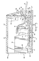
- the cover member is then aligned with the base member with the cable dressed over the first and third clamping walls on the base member as shown in Figure 3. Pressing the cover on to the base causes the free end of the second, clamping wall 35 to deform a discrete portion of the cable to extend transversely of the cable axis and draw more cable from the exterior of the connector as shown in Figure 4A.
- the cable is held by the relatively sharp edge 33 of the first wall and slides across the surface 38 of the second wall during such movement. Any tendency for the cable to pivot away from the edge 33 will be prevented by engagement ultimately with the cable locating lugs 45.
- Engagement between the skirt 48 on the cover member and the upstanding base wall 53 and the skirt and the ribs 64 will assist m guiding the first and second clamping walls together into parallel relation interdigitating with the third and fourth walls.
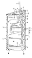
- the second wall will tend to be moved by the cable away from the first wall during initial closure together of the clamping members avoiding excessive frictional drag on the cable and excessive closure forces until cam surface 42 engages the free end of the third wall progressively urging the second wall back towards the first wall until the transversely deformed portion of the cable is gripped by the first and second walls as shown in Figure 4C.
- the barbs 29 assist in restraining the cable from being withdrawn away from the terminals during the latter stages of movement to the closed condition.
- Latching detents 49 and eyes 50 on the cover member and the recesses 55 and catches 56 on the base member snap into engagement in the fully closed condition shown in Figure 5,
- the cable clamp can, within limits, accommodate a range of cable sizes to avoid a need to manufacture, store and transport a range of parts.
- the cable clamp also requires only two components each of which can be manufactured economically using mass production techniques.
Landscapes
- Details Of Connecting Devices For Male And Female Coupling (AREA)
- Coupling Device And Connection With Printed Circuit (AREA)
- Insulated Conductors (AREA)
- Cable Accessories (AREA)
- Processing Of Terminals (AREA)
- Multi-Conductor Connections (AREA)
Claims (13)
Priority Applications (1)
| Application Number | Priority Date | Filing Date | Title |
|---|---|---|---|
| AT83304824T ATE17619T1 (de) | 1982-09-02 | 1983-08-22 | Kabelklemme fuer einen elektrischen verbinder. |
Applications Claiming Priority (2)
| Application Number | Priority Date | Filing Date | Title |
|---|---|---|---|
| US06/414,261 US4749370A (en) | 1982-09-02 | 1982-09-02 | Cable clamp for an electrical connector |
| US414261 | 1995-03-31 |
Publications (3)
| Publication Number | Publication Date |
|---|---|
| EP0102798A2 EP0102798A2 (fr) | 1984-03-14 |
| EP0102798A3 EP0102798A3 (en) | 1984-04-11 |
| EP0102798B1 true EP0102798B1 (fr) | 1986-01-22 |
Family
ID=23640664
Family Applications (1)
| Application Number | Title | Priority Date | Filing Date |
|---|---|---|---|
| EP83304824A Expired EP0102798B1 (fr) | 1982-09-02 | 1983-08-22 | Serre-câble pour un connecteur électrique |
Country Status (12)
| Country | Link |
|---|---|
| US (1) | US4749370A (fr) |
| EP (1) | EP0102798B1 (fr) |
| JP (1) | JPS5963676A (fr) |
| AT (1) | ATE17619T1 (fr) |
| BR (1) | BR8304745A (fr) |
| CA (1) | CA1215152A (fr) |
| DE (1) | DE3361930D1 (fr) |
| ES (1) | ES274122Y (fr) |
| HK (1) | HK28689A (fr) |
| IE (1) | IE54544B1 (fr) |
| MX (1) | MX153974A (fr) |
| SG (1) | SG889G (fr) |
Families Citing this family (19)
| Publication number | Priority date | Publication date | Assignee | Title |
|---|---|---|---|---|
| JPS61269876A (ja) * | 1985-05-23 | 1986-11-29 | 第一電子工業株式会社 | グランド端子をもつ多極コネクタへのテ−プ電線接続方法 |
| FR2597668B1 (fr) * | 1986-04-22 | 1988-06-17 | Thomson Csf | Bride pour connecteur de cable plat, assurant la tenue mecanique du cable |
| GB2205202A (en) * | 1987-05-29 | 1988-11-30 | Allied Corp | Improved electrical connection devices for use with flat cable |
| US4906196A (en) * | 1988-02-24 | 1990-03-06 | Amp Incorporated | Network distribution assembly |
| US4850901A (en) * | 1988-04-14 | 1989-07-25 | Brintec Corporation | Communications outlet |
| NL9000721A (nl) * | 1990-03-27 | 1991-10-16 | Du Pont Nederland | Tweedelige opneemcontacteenheid voor een modulair klinksamenstel. |
| US5145404A (en) * | 1990-10-01 | 1992-09-08 | United Technologies Automotive, Inc. | Switch terminal board cover with electrical lead isolation |
| ATE114879T1 (de) * | 1991-06-11 | 1994-12-15 | Siemens Ag | Installationsgehäuse mit drahtzugentlastung. |
| US5199891A (en) * | 1992-05-13 | 1993-04-06 | Amp Incorporated | Cable strain relief for shielded electrical connector |
| DE4217976A1 (de) * | 1992-05-30 | 1993-12-02 | Swf Auto Electric Gmbh | Elektrische Schaltereinheit, insbesondere für Kraftfahrzeuge |
| US5624273A (en) * | 1995-04-21 | 1997-04-29 | The Whitaker Corporation | Insulation displacement contact with strain relief |
| US5649829A (en) * | 1995-07-21 | 1997-07-22 | Miller; Mitchell Eugene | Low profile distribution adapter for use with twisted pair cables |
| US5626491A (en) * | 1995-08-18 | 1997-05-06 | The Whitaker Corporation | Electrical connector strain relief for cable |
| FR2791516B1 (fr) * | 1999-03-26 | 2001-05-11 | Siemens Automotive Sa | Boitier electronique |
| US6175080B1 (en) * | 1999-04-28 | 2001-01-16 | Tektronix, Inc. | Strain relief, pull-strength termination with controlled impedance for an electrical cable |
| US6616260B2 (en) * | 2001-05-25 | 2003-09-09 | Hewlett-Packard Development Company, L.P. | Robust bit scheme for a memory of a replaceable printer component |
| US7798869B1 (en) | 2008-06-10 | 2010-09-21 | Woodard Govenor Company | Electrical connector |
| JP5579571B2 (ja) * | 2010-10-26 | 2014-08-27 | 株式会社マキタ | 電源コードの配設構造 |
| KR102507945B1 (ko) * | 2018-03-26 | 2023-03-09 | 후루카와 덴키 고교 가부시키가이샤 | 케이블 권취 장치 및 슬라이드 시트용 플랫 케이블 라우팅 구조 |
Family Cites Families (12)
| Publication number | Priority date | Publication date | Assignee | Title |
|---|---|---|---|---|
| US2920129A (en) * | 1956-12-05 | 1960-01-05 | Illinois Tool Works | Strain relief grommet |
| FR1307599A (fr) * | 1960-12-07 | 1962-10-26 | Ibm | Dispositif empêchant la transmission des efforts de traction exercés sur des câbles |
| DE1171043B (de) * | 1961-08-02 | 1964-05-27 | Siemens Ag | Zugsicherung fuer Apparateschnuere |
| FR93122E (fr) * | 1967-06-06 | 1969-02-14 | Pierre Hurault | Perfectionnements aux fiches pour prises de courant. |
| US3860318A (en) * | 1973-04-04 | 1975-01-14 | Amp Inc | Pre-loaded electrical connector |
| GB1551298A (en) * | 1977-07-29 | 1979-08-30 | Gen Electric Co Ltd | Electrical connectors |
| JPS5745871Y2 (fr) * | 1978-09-08 | 1982-10-08 | ||
| US4186948A (en) * | 1978-10-02 | 1980-02-05 | Cronk Allan D | Pipe joint clamp |
| US4231628A (en) * | 1978-12-14 | 1980-11-04 | Amp Incorporated | Electrical connector receptacles |
| DE2931331A1 (de) * | 1979-08-02 | 1981-02-05 | Wolfgang Freitag | Elektrischer steckverbinder, insbesondere lautsprecherstecker |
| US4420204A (en) * | 1979-11-19 | 1983-12-13 | Gte Products Corporation | Dead-front electrical wiring device attachable to a power cord |
| GB2067365B (en) * | 1980-01-09 | 1984-11-28 | Crabtree Electrical Ind Ltd | Electric plugs |
-
1982
- 1982-09-02 US US06/414,261 patent/US4749370A/en not_active Expired - Fee Related
-
1983
- 1983-08-22 DE DE8383304824T patent/DE3361930D1/de not_active Expired
- 1983-08-22 EP EP83304824A patent/EP0102798B1/fr not_active Expired
- 1983-08-22 AT AT83304824T patent/ATE17619T1/de not_active IP Right Cessation
- 1983-08-29 ES ES1983274122U patent/ES274122Y/es not_active Expired
- 1983-08-31 IE IE2035/83A patent/IE54544B1/en not_active IP Right Cessation
- 1983-08-31 CA CA000435756A patent/CA1215152A/fr not_active Expired
- 1983-08-31 MX MX198575A patent/MX153974A/es unknown
- 1983-08-31 BR BR8304745A patent/BR8304745A/pt not_active IP Right Cessation
- 1983-09-01 JP JP58161203A patent/JPS5963676A/ja active Granted
-
1989
- 1989-01-06 SG SG8/89A patent/SG889G/en unknown
- 1989-04-06 HK HK286/89A patent/HK28689A/xx not_active IP Right Cessation
Also Published As
| Publication number | Publication date |
|---|---|
| CA1215152A (fr) | 1986-12-09 |
| IE832035L (en) | 1984-03-02 |
| MX153974A (es) | 1987-03-03 |
| ES274122Y (es) | 1984-08-01 |
| JPS5963676A (ja) | 1984-04-11 |
| HK28689A (en) | 1989-04-14 |
| SG889G (en) | 1989-06-02 |
| JPS6346541B2 (fr) | 1988-09-16 |
| IE54544B1 (en) | 1989-11-08 |
| ATE17619T1 (de) | 1986-02-15 |
| EP0102798A3 (en) | 1984-04-11 |
| DE3361930D1 (en) | 1986-03-06 |
| EP0102798A2 (fr) | 1984-03-14 |
| ES274122U (es) | 1984-01-16 |
| US4749370A (en) | 1988-06-07 |
| BR8304745A (pt) | 1984-04-10 |
Similar Documents
| Publication | Publication Date | Title |
|---|---|---|
| EP0102798B1 (fr) | Serre-câble pour un connecteur électrique | |
| US7371106B2 (en) | Strain-relief device for a plug-in connection in communications and data systems | |
| US5941733A (en) | Universal serial bus plug connector | |
| US6017233A (en) | Floating panel mount system for electrical connectors | |
| US5961351A (en) | Universal serial Bus B-type plug connector | |
| US4875876A (en) | Electrical connector for overlapped conductors | |
| US4169648A (en) | Strain relief and back cover for electrical connector | |
| US4127315A (en) | Cable clamp and hood constructions for use with ribbon connectors | |
| US4405193A (en) | Preloaded electrical connector | |
| EP0251736B1 (fr) | Dispositif de fixation de fils dans un connecteur électrique | |
| US4647129A (en) | Electrical connector | |
| US4648678A (en) | Electrical connector | |
| EP0527399B1 (fr) | Borne autodénudante | |
| US5320558A (en) | Quick connect and disconnect electrical terminal | |
| GB2110886A (en) | Electrical connector member | |
| US5659948A (en) | Termination tool for modular telephone connector | |
| GB2079073A (en) | Electrical connector with a wire strain relief device | |
| EP0516464B1 (fr) | Appareillage pour le soulagement de traction pour câbles dans un assemblage de connecteurs électriques | |
| EP0570039A1 (fr) | Borne électrique | |
| JPH05152029A (ja) | 歪み解消機能を備えたモジユラコネクタ組立体 | |
| US5599201A (en) | Circuit assembly having stamped circuitry with a wire trap | |
| EP0429136B1 (fr) | Assemblage de connecteur | |
| US4540224A (en) | Grounding clip for use with shielded, jacketed flat cable | |
| US5127153A (en) | Insulation-piercing connector with clamping lip, and tool for bending thereof | |
| US5718601A (en) | Electrical connector assembly |
Legal Events
| Date | Code | Title | Description |
|---|---|---|---|
| PUAI | Public reference made under article 153(3) epc to a published international application that has entered the european phase |
Free format text: ORIGINAL CODE: 0009012 |
|
| PUAL | Search report despatched |
Free format text: ORIGINAL CODE: 0009013 |
|
| AK | Designated contracting states |
Designated state(s): AT BE DE FR GB IT NL SE |
|
| AK | Designated contracting states |
Designated state(s): AT BE DE FR GB IT NL SE |
|
| 17P | Request for examination filed |
Effective date: 19840521 |
|
| ITF | It: translation for a ep patent filed | ||
| GRAA | (expected) grant |
Free format text: ORIGINAL CODE: 0009210 |
|
| AK | Designated contracting states |
Designated state(s): AT BE DE FR GB IT NL SE |
|
| REF | Corresponds to: |
Ref document number: 17619 Country of ref document: AT Date of ref document: 19860215 Kind code of ref document: T |
|
| REF | Corresponds to: |
Ref document number: 3361930 Country of ref document: DE Date of ref document: 19860306 |
|
| ET | Fr: translation filed | ||
| PLBE | No opposition filed within time limit |
Free format text: ORIGINAL CODE: 0009261 |
|
| STAA | Information on the status of an ep patent application or granted ep patent |
Free format text: STATUS: NO OPPOSITION FILED WITHIN TIME LIMIT |
|
| 26N | No opposition filed | ||
| ITTA | It: last paid annual fee | ||
| REG | Reference to a national code |
Ref country code: GB Ref legal event code: 732E |
|
| EAL | Se: european patent in force in sweden |
Ref document number: 83304824.2 |
|
| PGFP | Annual fee paid to national office [announced via postgrant information from national office to epo] |
Ref country code: SE Payment date: 19950719 Year of fee payment: 13 |
|
| PGFP | Annual fee paid to national office [announced via postgrant information from national office to epo] |
Ref country code: AT Payment date: 19950724 Year of fee payment: 13 |
|
| PGFP | Annual fee paid to national office [announced via postgrant information from national office to epo] |
Ref country code: BE Payment date: 19950905 Year of fee payment: 13 |
|
| PG25 | Lapsed in a contracting state [announced via postgrant information from national office to epo] |
Ref country code: AT Effective date: 19960822 |
|
| PG25 | Lapsed in a contracting state [announced via postgrant information from national office to epo] |
Ref country code: SE Effective date: 19960823 |
|
| PG25 | Lapsed in a contracting state [announced via postgrant information from national office to epo] |
Ref country code: BE Effective date: 19960831 |
|
| BERE | Be: lapsed |
Owner name: AMP INC. (UNE SOC. DE PENNSYLANIE) Effective date: 19960831 |
|
| EUG | Se: european patent has lapsed |
Ref document number: 83304824.2 |
|
| PGFP | Annual fee paid to national office [announced via postgrant information from national office to epo] |
Ref country code: NL Payment date: 19980623 Year of fee payment: 16 |
|
| PGFP | Annual fee paid to national office [announced via postgrant information from national office to epo] |
Ref country code: GB Payment date: 19980702 Year of fee payment: 16 |
|
| PGFP | Annual fee paid to national office [announced via postgrant information from national office to epo] |
Ref country code: FR Payment date: 19980806 Year of fee payment: 16 |
|
| PGFP | Annual fee paid to national office [announced via postgrant information from national office to epo] |
Ref country code: DE Payment date: 19980827 Year of fee payment: 16 |
|
| PG25 | Lapsed in a contracting state [announced via postgrant information from national office to epo] |
Ref country code: GB Free format text: LAPSE BECAUSE OF NON-PAYMENT OF DUE FEES Effective date: 19990822 |
|
| PG25 | Lapsed in a contracting state [announced via postgrant information from national office to epo] |
Ref country code: NL Free format text: LAPSE BECAUSE OF NON-PAYMENT OF DUE FEES Effective date: 20000301 |
|
| GBPC | Gb: european patent ceased through non-payment of renewal fee |
Effective date: 19990822 |
|
| PG25 | Lapsed in a contracting state [announced via postgrant information from national office to epo] |
Ref country code: FR Free format text: LAPSE BECAUSE OF NON-PAYMENT OF DUE FEES Effective date: 20000428 |
|
| NLV4 | Nl: lapsed or anulled due to non-payment of the annual fee |
Effective date: 20000301 |
|
| PG25 | Lapsed in a contracting state [announced via postgrant information from national office to epo] |
Ref country code: DE Free format text: LAPSE BECAUSE OF NON-PAYMENT OF DUE FEES Effective date: 20000601 |
|
| REG | Reference to a national code |
Ref country code: FR Ref legal event code: ST |