EP0102569B1 - Electric corona discharge device, method for making said device and electrostatic treatment apparatus comprising said device - Google Patents
Electric corona discharge device, method for making said device and electrostatic treatment apparatus comprising said device Download PDFInfo
- Publication number
- EP0102569B1 EP0102569B1 EP83108152A EP83108152A EP0102569B1 EP 0102569 B1 EP0102569 B1 EP 0102569B1 EP 83108152 A EP83108152 A EP 83108152A EP 83108152 A EP83108152 A EP 83108152A EP 0102569 B1 EP0102569 B1 EP 0102569B1
- Authority
- EP
- European Patent Office
- Prior art keywords
- electrodes
- raw sheet
- phase
- corona discharge
- electrode
- Prior art date
- Legal status (The legal status is an assumption and is not a legal conclusion. Google has not performed a legal analysis and makes no representation as to the accuracy of the status listed.)
- Expired
Links
Images


Classifications
-
- H—ELECTRICITY
- H05—ELECTRIC TECHNIQUES NOT OTHERWISE PROVIDED FOR
- H05F—STATIC ELECTRICITY; NATURALLY-OCCURRING ELECTRICITY
- H05F3/00—Carrying-off electrostatic charges
- H05F3/04—Carrying-off electrostatic charges by means of spark gaps or other discharge devices
-
- D—TEXTILES; PAPER
- D06—TREATMENT OF TEXTILES OR THE LIKE; LAUNDERING; FLEXIBLE MATERIALS NOT OTHERWISE PROVIDED FOR
- D06M—TREATMENT, NOT PROVIDED FOR ELSEWHERE IN CLASS D06, OF FIBRES, THREADS, YARNS, FABRICS, FEATHERS OR FIBROUS GOODS MADE FROM SUCH MATERIALS
- D06M10/00—Physical treatment of fibres, threads, yarns, fabrics, or fibrous goods made from such materials, e.g. ultrasonic, corona discharge, irradiation, electric currents, or magnetic fields; Physical treatment combined with treatment with chemical compounds or elements
- D06M10/02—Physical treatment of fibres, threads, yarns, fabrics, or fibrous goods made from such materials, e.g. ultrasonic, corona discharge, irradiation, electric currents, or magnetic fields; Physical treatment combined with treatment with chemical compounds or elements ultrasonic or sonic; Corona discharge
- D06M10/025—Corona discharge or low temperature plasma
-
- B—PERFORMING OPERATIONS; TRANSPORTING
- B03—SEPARATION OF SOLID MATERIALS USING LIQUIDS OR USING PNEUMATIC TABLES OR JIGS; MAGNETIC OR ELECTROSTATIC SEPARATION OF SOLID MATERIALS FROM SOLID MATERIALS OR FLUIDS; SEPARATION BY HIGH-VOLTAGE ELECTRIC FIELDS
- B03C—MAGNETIC OR ELECTROSTATIC SEPARATION OF SOLID MATERIALS FROM SOLID MATERIALS OR FLUIDS; SEPARATION BY HIGH-VOLTAGE ELECTRIC FIELDS
- B03C7/00—Separating solids from solids by electrostatic effect
- B03C7/02—Separators
- B03C7/04—Separators with material carriers in the form of trays, troughs, or tables
-
- B—PERFORMING OPERATIONS; TRANSPORTING
- B05—SPRAYING OR ATOMISING IN GENERAL; APPLYING FLUENT MATERIALS TO SURFACES, IN GENERAL
- B05B—SPRAYING APPARATUS; ATOMISING APPARATUS; NOZZLES
- B05B5/00—Electrostatic spraying apparatus; Spraying apparatus with means for charging the spray electrically; Apparatus for spraying liquids or other fluent materials by other electric means
- B05B5/025—Discharge apparatus, e.g. electrostatic spray guns
- B05B5/03—Discharge apparatus, e.g. electrostatic spray guns characterised by the use of gas, e.g. electrostatically assisted pneumatic spraying
- B05B5/032—Discharge apparatus, e.g. electrostatic spray guns characterised by the use of gas, e.g. electrostatically assisted pneumatic spraying for spraying particulate materials
-
- B—PERFORMING OPERATIONS; TRANSPORTING
- B05—SPRAYING OR ATOMISING IN GENERAL; APPLYING FLUENT MATERIALS TO SURFACES, IN GENERAL
- B05B—SPRAYING APPARATUS; ATOMISING APPARATUS; NOZZLES
- B05B5/00—Electrostatic spraying apparatus; Spraying apparatus with means for charging the spray electrically; Apparatus for spraying liquids or other fluent materials by other electric means
- B05B5/025—Discharge apparatus, e.g. electrostatic spray guns
- B05B5/043—Discharge apparatus, e.g. electrostatic spray guns using induction-charging
-
- B—PERFORMING OPERATIONS; TRANSPORTING
- B05—SPRAYING OR ATOMISING IN GENERAL; APPLYING FLUENT MATERIALS TO SURFACES, IN GENERAL
- B05B—SPRAYING APPARATUS; ATOMISING APPARATUS; NOZZLES
- B05B5/00—Electrostatic spraying apparatus; Spraying apparatus with means for charging the spray electrically; Apparatus for spraying liquids or other fluent materials by other electric means
- B05B5/08—Plant for applying liquids or other fluent materials to objects
- B05B5/087—Arrangements of electrodes, e.g. of charging, shielding, collecting electrodes
- B05B5/088—Arrangements of electrodes, e.g. of charging, shielding, collecting electrodes for creating electric field curtains
-
- B—PERFORMING OPERATIONS; TRANSPORTING
- B65—CONVEYING; PACKING; STORING; HANDLING THIN OR FILAMENTARY MATERIAL
- B65G—TRANSPORT OR STORAGE DEVICES, e.g. CONVEYORS FOR LOADING OR TIPPING, SHOP CONVEYOR SYSTEMS OR PNEUMATIC TUBE CONVEYORS
- B65G54/00—Non-mechanical conveyors not otherwise provided for
- B65G54/02—Non-mechanical conveyors not otherwise provided for electrostatic, electric, or magnetic
-
- G—PHYSICS
- G03—PHOTOGRAPHY; CINEMATOGRAPHY; ANALOGOUS TECHNIQUES USING WAVES OTHER THAN OPTICAL WAVES; ELECTROGRAPHY; HOLOGRAPHY
- G03G—ELECTROGRAPHY; ELECTROPHOTOGRAPHY; MAGNETOGRAPHY
- G03G15/00—Apparatus for electrographic processes using a charge pattern
- G03G15/06—Apparatus for electrographic processes using a charge pattern for developing
- G03G15/08—Apparatus for electrographic processes using a charge pattern for developing using a solid developer, e.g. powder developer
- G03G15/0822—Arrangements for preparing, mixing, supplying or dispensing developer
-
- H—ELECTRICITY
- H01—ELECTRIC ELEMENTS
- H01T—SPARK GAPS; OVERVOLTAGE ARRESTERS USING SPARK GAPS; SPARKING PLUGS; CORONA DEVICES; GENERATING IONS TO BE INTRODUCED INTO NON-ENCLOSED GASES
- H01T19/00—Devices providing for corona discharge
Definitions
- Electrodes in which electrodes are provided on a surface of or within a dielectric body, a D.C. high voltage or an A.C. high voltage (including a sinusoidal wave, a rectangular wave, and a pulse-shaped high voltage) are applied between these electrodes to produce phenomena inherent to an electric field such as gaseous discharge or electro-mechanical phenomena, have been well known, and these phenomena are utilized as a ion source for charging or discharging of object matters or utilized for electro-mechanical operations such as adhesion, repulsion or transportation of object matters caused by an electric force.
- a D.C. high voltage or an A.C. high voltage including a sinusoidal wave, a rectangular wave, and a pulse-shaped high voltage
- Examples of such devices serving as a ion source have been disclosed in Japanese patent No. 99242, and Japanese patent applications No. 51-103328, No. 52-106400, No. 52-145838 and No. 56-155419.
- examples of such devices for utilizing for electro-mechanical operations have been disclosed in Japanese Patents No. 983218, No. 973106, No. 1009331, No. 981125, No. 1047574, No. 1048666, in Japanese Patent Publications No. 57-6385, No. 57-9856 and No. 57-24181, in Laid-open Japanese Patent Specification No. 52-108574, and in Japanese Patent Application No. 57-081779.
- the above-mentioned partial discharge becomes especially remarkable.
- synthetic resin or shaped anorganic insulator bonded by synthetic resin is used as a dielectric.
- the organic dielectric material such as synthetic resin or the like is locally deteriorated by the ion bombardment or electron bombardment caused by the above-described partial discharge, especially when an A.C. high voltage is applied, the deterioration proceeds quickly in a tree shape resulting in growth of insulation defects called "treeing", and eventually it is inevitable that breakdown between the electrodes applied with a high voltage would be generated within a relatively short period of time.
- anorganic insulator such as mica, ceramics, etc.
- a life can be somewhat prolonged, not only it becomes difficult to perfectly embed an electrode within the insulator, but also as the structure of the insulator is not dense, when an interval or a thickness of an insulator portion is made thin for the purpose of enhancing an electric field effect, likewise breakdown would arise momentarily at a low voltage, and therefore, it is impossible to construct an effective electrical corona discharge device.
- the electrical corona discharge device since an appropriate material is not obtained, the electrical corona discharge device has a very short life and a high cost.
- the electrical corona discharge device is dense, mechanically, electrically, chemically and thermally durable and highly reliable through the steps of employing highly pure and mechanically, electrically, chemically and thermally extremely durable ceramic material in the form of high purity alumina porcelain as dielectric material, disposing electrodes on the shaped material before sintering and sintering the shaped material integrally with the electrodes.
- a method is used in which high purity alumina preliminarily ground into powder having a grain diameter of several microns or less is bound by means of an organic binder, then a raw material sheet formed in a layer shape (called "green sheet") is produced, on the surface of the green sheet are formed electrodes by making use of an ink in which micro- fine powder of appropriate metal, for example, tungsten is dispersed with a thick film printing technique such as, for example, screen printing technique, the thus formed green sheet associated with electrode in itself singly, or after a plurality of such green sheets have been stacked and press-bonded, the formed multi-layer green sheet, is sintered within an appropriate reducing atmosphere such as a hydrogen furnace at a high temperature in the proximity of 1500°C.
- an appropriate reducing atmosphere such as a hydrogen furnace at a high temperature in the proximity of 1500°C.
- the electrical corona discharge device by making the electrical corona discharge device from a multilayer green sheet, it becomes possible to dispose a part of the electrodes as embedded in a sandwich form within the fine-ceramic dielectric in a single layer or in multiple layers, and thereby it becomes possible to achieve a high degree of corona discharge effect, or to enhance safety by internally embedding an electrode to be applied with a high voltage.
- fine ceramic dielectric material to be used according to the present invention highly pure alumina porcelain having a purity of 90% or higher is preferable.
- an electrical corona discharge device is formed in a multilayer structure, it is possible to make it less expensive or to enhance its performance by using a high purity alumina porcelain layer and an alumina porcelain layer having a relatively low purity and hence being less expensive in combination, by using fine ceramic materials of different kinds having different natures in different layers or at different locations in combination, or by using a fine ceramic material and the other dielectric materials (synthetic resin, mica, glass, ERP) in different layers or at different locations in combination.
- synthetic resin, mica, glass, ERP synthetic resin, mica, glass, ERP
- the device may be subjected to improvement in the nature of the surface such as smoothening of the surface or creation of electrical conductivity by applying a suitable glaze on the surface, and in addition, the device can be subjected to improvements in its surface nature by depositing a Teflon layer, a silicon layer and a surface layer of another appropriate material.
- a high melting point metal that is easily integrated with the fine ceramic material used as a base material when they are sintered together and that has a coefficient of thermal expansion as close as that of the fine ceramic material, is preferable.
- tungsten is most suitable.
- the electrode material could have its surface plated with appropriate metal such as nickel for the purpose of preventing oxidation, protecting its surface or facilitating soldering, and moreover on the electrode itself could be thinly applied a glaze layer, an alumina insulator film or another surface layer.
- the novel device can be formed and used not only in a plane shape but also in an arbitrary curved surface shape (spherical shape, semi-cylindrical shape, circular column shape, polygonal shape, step-like shape, etc.), and when practicing such a curved surface shape, in the stage of a green sheet associated with electrodes which is still rich in flexibility, the green sheet could be shaped into a desired configuration and then sintered.
- the field of application of the electrical corona discharge device according to the present invention extends over every one of charging and/or discharging apparatuses of object matters and electro-mechanical operation apparatuses of object matters, also the field of application involves all the subject matters of the prior art referred to in the introduction part of this specification.
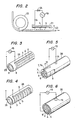
- Figs. 1A to 1F show one preferred embodiment of an electrical corona discharge device according to the present invention. These figures show a method for making a device, in which a group of elongated corona discharge electrodes are disposed on a rectangular fine ceramic dielectric plate in its lengthwise direction, a sheet of induction electrode having a size opposed to the whole of said corona discharge electrode group is embedded within the dielectric plate under the corona discharge electrode group, and then the entire assembly is sintered according to the present invention.
- Fig. 1A to 1F show a method for making a device, in which a group of elongated corona discharge electrodes are disposed on a rectangular fine ceramic dielectric plate in its lengthwise direction, a sheet of induction electrode having a size opposed to the whole of said corona discharge electrode group is embedded within the dielectric plate under the corona discharge electrode group, and then the entire assembly is sintered according to the present invention.
- 1A is a perspective view showing a top surface of an upper green sheet, in which on an upper surface 2 of the rectangular upper green sheet 1 are formed a plurality of parallel corona electrodes 3, 4 and 5 directed in the lengthwise direction of about 1 mm in width and about 100 pm in thickness at an interval of about 5 mm with ink having tungsten micro-fine powder dispersed therein through a screen printing technique, further these electrodes are connected to a common conductor 6 printed through a similar method, and then a terminal conductor 7 is further connected by printing.
- Fig. 1B is a perspective view showing a lower surface 8 of the above-described upper green sheet 1, in which a rectangular planar induction electrode 9 is formed on the lower surface portion opposed to the entire area of the upper surace occupied by the electrodes 3, 4 and 5 by printing with ink having tungsten micro-fine powder dispersed therein through a similar screen printing technique.
- Fig. 1B is a perspective view showing a lower surface 8 of the above-described upper green sheet 1, in which a rectangular planar induction electrode 9 is formed on the lower surface portion opposed to the entire area of the upper surace occupied by the electrodes 3, 4 and 5 by printing with ink having tungsten micro-fine powder dispersed therein through a similar screen printing technique.
- 1C is a perspective view showing an upper surface 11 of a lower sheet 10, in which a hole 12 of about 1 mm in diameter is provided at the center of the same sheet 10 penetrating therethrough, this hole is filled with ink having tungsten micro-fine powder dispersed therein to form a conductor penetrating through the sheet 10, and further a disc-shaped contacting conductor portion 13 of about 10 mm in diameter with the hole 12 located at its center, is formed by screen printing similarly with ink having tungsten micro-fine powder dispersed therein.
- a terminal conductor 7a to be connected with the terminal conductor 7.
- 1D is a perspective view showing a lower surface 14 of the lower sheet 10, in which a disc-shaped terminal conductor portion 15 of about 10 mm in diameter with the aforementioned hole 12 filled with ink having tungsten micro-fine powder dispersed therein located at its center, is formed by screen printing similarly with ink having tungsten micro-fine powder dispersed therein.
- a disc-shaped terminal conductor portion 15 of about 10 mm in diameter with the aforementioned hole 12 filled with ink having tungsten micro-fine powder dispersed therein located at its center is formed by screen printing similarly with ink having tungsten micro-fine powder dispersed therein.
- another disc-shaped terminal conductor portion 16 of about 10 mm in diameter by screen printing similarly with ink having tungsten micro-fine powder dispersed therein, and this terminal conductor portion 16 is connected to the terminal conductor 7a through a terminal conductor 17 printed with similar ink.
- aforementioned respective sheets 1 and 10 are superposed, and after they have been shaped by hot press bonding, they are sintered within a hydrogen furnace. Then they are sintered with the planar induction electrode 9 airtightly sandwiched between the respective sheets 1 and 10, so that the electrode 9 is embedded within a dielectric plate 18 which has been integrally sintered from the upper and lower sheets. And the aforementioned induction electrode 9 is fused jointly with the disc-shaped terminal conductor portion 13 and is connected to the disc-shaped terminal conductor portion 15 on the rear surface of the dielectric plate 18 as conducting through the hole 12.
- Fig. 1 is a perspective view showing electrode surfaces of an electrical corona discharge device which was fabricated in the above-described manner, in which a ceramic plate portion made of the upper green sheet is partly cut away to show a ceramic plate portion made of the lower green sheet and the induction electrode 9.
- Fig. 1 F shows a cross-section view of this device.
- the surfaces of the electrodes 3,4 and 5, the conductors 6, 7, 7a and 17 and the terminal conductor portions 15 and 16 are plated by nickel in order to prevent oxidation of tungsten, and thereby soldering of external conductors to the terminal conductor portions 15 and 16 is faciliated. If a high frequency A.C. high voltage is applied from a high frequency A.C.
- the high voltage source 19 via the terminal conductor portions 15 and 16 not shown between the corona electrode group 3, 4 and 5 and the planar induction electrode 9 by the intermediary of the fine ceramic dielectric layer 20 (the electrodes 3, 4 and 5 being grounded for the purpose of safety), then high frequency corona discharge is generated from the edges of the electrodes 3, 4 and 5 along the surface of the dielectric plate 18, and thereby plasma containing plenty of positive and negative ions is formed. Accordingly, if this device is brought close to a proximity of a charged body, ions of the opposite polarity to that charge are supplied from this plasma to the aforementioned charged body, and thereby the charged body can be quickly discharged. In other words, the device can be used as a discharger or a charge remover. In this case, as a matter of course, repetitive pulse voltages could be applied by employing a pulsed high voltage source in place of the high frequency A.C. high voltage source 19.
- Fig. 2 shows one example in which the device 21 in Fig. 1 F is utilized to remove electrical charge charged by friction on a rubber belt 23 after passing around a roller 22, in which the device 21 is disposed in the close proximity of a charged rubber belt surface, and in the illustrated example, negative ions are attracted from the plasma formed by the corona electrode group 3, 4 and 5 to neutralize the positive charge on the rubber belt surface.
- Reference numeral 24 designates a protective resistor.
- Fig. 3 shows an electrical corona discharge device constructed by bending the upper sheet 1 shown in Figs. 1A and 1B about an axis directed in the lengthwise direction of the sheet so that the upper surface of the green sheet 1 may come outside to form a hollow cylinder 25, and then sintering the hollow cylinder-shaped green sheet.
- a high frequency A.C. high voltage source 19 is connected to the thin wire-shaped corona discharge electrodes 3,4 and 5 which are arrayed on the outer cylinder surface in the lengthwise direction parallel to each other and at equal intervals and the induction electrode 9 formed in a cylindrical surface shape on the inner cylinder surface as shown in Fig. 3 and then a high frequency A.C.
- an electrical corona discharge device 26 serving as a cylindrical plasma ion source can be constructed.
- the thin wire-shaped corona discharge electrodes 3, 4 and 5 could be disposed on the cylinder surface so as to be perpendicular to generating lines.
- Fig. 4 shows such modification.
- Fig. 5 shows a ion source constructed by superposing the upper sheet shown in Figs. 1A and 1B and the lower sheet shown in Figs. 1 C and 1 D with each other, stacking and press-bonding them into the shape shown in Fig. 1 E, thereafter bending the assembly about an axis directed in the lengthwise direction of the sheets so that the upper surface having the thin wire-shaped corona discharge electrodes 3, 4, 5, ... may come inside to form a hollow cylinder 26, and then sintering the hollow cylinder-shaped green sheet. If a high frequency A.C. high voltage is applied between the thin wire-shaped corona discharge electrodes 3, 4, 5, ...
- Fig. 6 shows one modification of the device shown in Fig. 5, in which thin wire-shaped corona discharge electrodes 3, 4, 5, ... are arrayed on an inner surface of a hollow cylinder 26 in the direction perpendicular to the axis of the cylinder.
- the cylinder-shaped device shown in Figs. 5 and 6 can be used for removing electrical charge of a liquid which has been charged by friction with a pipe by interposing the device in the midway of a pipe line conveyor of a liquid having a high resistance.
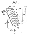
- Fig. 7 illustrates an example of employing an electrical corona discharge device 18 in a powder painting apparatus.
- the device 18 is disposed to confront a suspended, grounded substrate 38.
- a D.C. high voltage source 30 is used to run negative ions from said plasma toward said substrate 38.
- a powder is concurrently fed from above to the surface of electric field device 18 by way of a pipe line 39 and a slit 41 of a triangular formed feeder 40. Thereupon, said powder is negatively charged due to bombardment by negative ions and is carried by electric force toward the substrate 38 to coat a surface thereof.
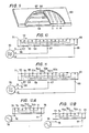
- Figs. 8 to 8E illustrate another embodiment of the electrical corona discharge device according to this invention.
- This embodiment is a three-phase electrical corona discharge device.
- three green sheets 50, 51, 52 as three layers.
- Fig. 8A is a perspective view of very thin surface layer green sheet 50 having a thickness of about 0.1-0.5 mm when viewed from above sideways. This sheet has no printed electrode.
- Fig. 8B is a perspective view of the upper surface of rectangular intermediate layer sheet 51 having a thickness of about 2 mm.
- many parallel narrow strip electrodes 53, 54, 55, 53a, 54a, 55a, 53b, 54b, 55b, ... are disposed by screen printing technique with tungsten micro-fine powder dispersion ink.
- Every third electrode of them is connected to one another to form three electrode groups u, v and w, consisting of electrodes, 53-53a-53b ..., 54-54a-54b ... and 55-55a-55b ..., respectively.
- the u, v and w phase voltages of a three-phase A.C. high voltage will be applied to respective electrode groups.
- three connecting conductors 56, 57 and 58 parallel to lengthwise direction of sheet are screen printed on the back surface of intermediate layer sheet 51 in the same manner, and the conductor 56 is connected to u-phase group of electrodes 53, 53a, 53b ... on the upper surface of intermediate layer sheet 51 by way of small holes 59, 59a, 59b ... which penetrate through sheet 51 and are filled with tungsten micro-fine powder dispersion ink, as shown in Fig. 8C.
- the conductor 57 is connected to v-phase group of electrodes 54, 54a, 54b ... on the upper surface of intermediate layer sheet 51 by way of similar small holes 60, 60a, 60b ....
- the conductor 58 is connected to w-phase group of electrodes 55, 55a, 55b ... on the upper surface of intermediate layer sheet 51 by way of similar small holes 61, 61a, 61b ....
- the connecting conductors 56, 57, 58 constitute conducting means for applying u-phase, v-phase and w-phase voltages of a three-phase A.C. high voltage to u-phase group of electrodes, v-phase group of electrodes and w-phase group of electrodes, respectively.
- Fig. 8D is a perspective view of the upper surface of a base layer green sheet 52 of 3 mm in thickness
- Fig. 8E is a perspective view of the rear surface thereof.
- Reference numerals 62a, 63a and 64a designate small holes which penetrate the sheet 52 and are filled with tungsten powder dispersion ink.
- disc-shaped contacting conductor parts 62,63,64 of about 10 mm in diameter on the upper surface
- disc-shaped terminal conductor parts 66, 67, 68 of about 10 mm in diameter on the rear surface.
- Each of said conductor parts has been screen printed with tungsten powder dispersion ink.
- the combinations 62-66, 63 ⁇ 67 and 64-68 are positioned so as to be connected by contact to conductors 56, 57 and 58, respectively.
- a three-phase electrical corona discharge device 69 As shown by Fig. 9, is completed.
- this device there are provided three-phase electrode groups u, v and w inserted in fine ceramic matrix, beneath a smooth thin fine ceramic layer, and, under said electrodes, connecting conductors 56, 57 and 58 embedded in the same fine ceramic matrix, which are connected to u-phase, v-phase and w-phase electrode groups.
- high voltage source 70 are applied to the three-phase electrode groups of this device 69 in the sequence u-phase, v-phase, w-phase by way of terminal conductor parts 66, 67, 68, as shown by a schematic diagram of a model in Fig. 10, a travelling wave which travels in the phase sequence direction, as shown by arrow 72, along surface 71 of device 69 is generated. Consequently, if particles of a powder are placed on the surface 71 of device 69, they are charged by contact with the surface and then violently repelled and floated from the surface due to the action of said travelling wave. They are conveyed in floating state in the direction of arrow 72.
- the most important electromechanical actions to a powder of this three-phase corona discharge device consist in these charging by contact, repelling and transporting.
- this device can be utilized for preventing the adherence and the accumulation of powder and for transporting a powder. If the value of an impressed three-phase A.C. high voltage is being increased, a kind of electrodeless A.C. corona discharge is generated above a certain critical value of voltage Vc and the air on the surface is electrically dissociated to produce positive and negative ions. In this situation, the above-mentioned electromechanical actions, such as repelling and transporting, become more vigorous.
- a vigorous A.C. corona discharge generates around surfaces exposed to air of metal electrode group of 53, 53a, 53b, ..., even if at relatively low voltage, and said repelling and transporting actions are promoted.
- This device is referred to as one-phase-exposed type.
- modifications of the device in Fig. 11, that is, devices wherein two phase electrode groups or all three phase groups are exposed are also employable.
- a so-called single-phase electrical corona discharge device 75 which has single-phase electrodes 73, 74, 73a, 74a ... as shown in Fig. 12A or Fig. 12B, in place of three-phase electrodes.
- a single-phase A.C. high voltage from a single-phase A.C. high voltage source 78 is applied between the electrode group 73-73a-73b ... and the electrode group 74-74a-74b ..., each electrode member of one group being adjacent to electrode members of the other group, by way of terminal conductor parts 76 and 77, as shown by Figs.
- Single-phase devices of all these types can be employed in constructing pipe lines for transporting a pulverized or granular material and in lining inner walls of powder painting booth for sweeping off adhered particles or preventing adhesion of particles.
- these single-phase devices when these single-phase devices are disposed obliquely, particles of pulverized or granular material placed on devices are subject to vigorous agitating and floating action and slide downwards along the surface of the device due to gravity. Therefore, the devices can be utilized for conveying pulverized or granular material.
- changes in connection enable the use of a multi-phse A.C. source in place of three-phase A.C. source 70.
- a multi-phase A.C. source can be used.
- electrodes to be exposed should be exchanged depending on change in phases.
- a thin insulating alumina layer which has been formed by applying a finely divided alumina dispersion ink onto an intermediate layer sheet by screen printing and then have been sintered can be employed.
- the surface layer 50 can be made especially thin.
- Fig. 13 shows an example of application wherein a three-phase contact type electrical corona discharge device according to this invention is utilized to compose a conveyor machine for pulverized or granular material.
- a lower surface 80 and an upper surface 81 of the inner wall of a flume 79 having rectangular horizontal section are paved with a number of plate form three-phase contact type devices 82, 82a, 82b, ... and 83, 83a, 83b ... which have been shown in Fig. 10 or 11.
- Three-phase A.C. high voltages from three-phase A.C. high voltage sources 84,85 are applied to the respective group of devices and a travelling wave which travels in the phase sequence direction as shown by arrow 86 is generated.
- a high voltage source 92 is connected between neutral points 90, 91 (for example, neutral point of secondary winding or star-connected boosting transformer) of three-phase A.C. high voltage sources 84, 85 to generate a vertical D.C. field in the flume, the floating effect is usually enhanced and, as a result, the transporting capacity increases.
- a single-phase A.C. high voltage source 94 is connected between neutral points 90, 91 in place of D.C. high voltage source 92 by changing over a switch 93 to the right hand, as the case may be. Similar effects are obtained. In such a conveyor, when the A.C. voltages of three-phase A.C. high voltage source 84, 85 is raised above corona initiation voltage Vc, A.C.
- corona discharges are generated on the surfaces ofthree- phase contact type devices 82, 82 ... and 83, 83a ... and plasma appears as mentioned above. If the powder has inherently an excessive surface charge and tends to coagulate, such a powder is momentarily discharged under the action of plasma generated in said conveyor during being conveyed. Thus, the powder collected from the right hand end 95 of flume is free-flowing and can be handled with ease. Such a surface modification of powder by plasma is referred to as passivation.
- the electrical corona discharge devices according to this invention shown in Figs. 10, 11, 12A, 12B and 13 and Fig. 14to be explained hereinafter can be utilized for passivation operation of powder.
- the conveyor machine or devices shown in Figs. 10-13 can transport fibres, sheet materials and liquids, besides powder, not only in the horizontal direction, but also in an obliquely upward direction and in the vertically upward direction with ease.
- the object matters can be further easily conveyed in an obliquely downward direction.
- Fig. 14 shows a cylindrical three-phase electrical corona discharge device 96 which has been constructed by bending a three-phase contact type device shown in Fig. 9 of this invention as multi-layer green sheet about an axis in the longitidinal direction so that a cylinder may be formed and the upper surface of said green sheet may come inside of a hollow cylinder.
- Said device 96 can be used for conveying or passivation- treating an introduced powder, sheet material, fibre, or liquid.
- the device can be employed for discharging these materials.
- Fig. 15 shows an example wherein a cylindrical three-phase electrical corona discharge device according to this invention is used to compose a heat pipe.
- reference numeral 96 designates a cylindrical three-phase device shown in Fig. 14. At both ends of device are provided containers 100, 101 for working fluid, said containers having the respective heat transfer surfaces 102, 103.
- the device 96 is fed with a three-phase A.C. high voltage from a three-phase A.C. high voltage source 70 by way of terminals 66, 67, 68 a travelling wave is generated in the direction of arrow 86, the working fluid collected in the container 100 positioned in cold part is conveyed to the right upward along the inner wall of cylinder 96 and flows into the container 101 positioned in hot part.
- the working fluid in container 101 is heated by the heat introduced through heat transfer surface 103 to evaporate, moves then as gas through interior of cylinder 96 in the direction of arrow 104, and is condensed upon contacting with heat transfer surface 102 of container 100 to collect in the lower part of container 100. Through this circulation, heat is effectively and rapidly transmitted from heat transfer surface 103 to heat transfer surface 102. A hot area is cooled by heat transfer surface 103 and a cold area is heated by heat transfer surface 102.
- Fig. 16 represents an example of application wherein a three-phase electrical corona discharge device 75 of one-phase-exposed type shown in Fig. 12B according to this invention is employed in an electrostatic powder painting apparatus.
- said devices which are so disposed that the surfaces 71 provided with electrodes may face always inward constitute vertical walls 117, 118 and lower inclined walls 119, 120.
- Each of devices is fed with a three-phase A.C. high voltage, which is higher than the corona initiation voltage Vc, from a three-phase A.C. high voltage source 70.
- a D.C. high voltage of a grounded D.C. high voltage source 30 is applied to the neutral point of the source 70.
- a powder is introduced from the lower end by way of a pipe 123 and a T-formed inlet 124.
- the powder is conveyed upward along inclined walls 119, 120 under the action of the travelling wave in the apparatus, and then is elevated along vertical walls 117, 118.
- a negative ion current passes by action of D.C. field from plasma generated along inner faces of inclined walls 119, 120 and vertical walls 117, 118 to substrate 122.
- the powder is negatively charged by bombardment of said negative ion current, and is driven under the action of D.C. field to the surface of grounded substrate 122 to adhere thereon. Particles which have not adhered fall downward and are conveyed upward in the same manner as mentioned above, to re-enter into coating operation.
- the coated substrate 122 is introduced in an oven and baked to form a finished paint coating on the surface.
- Fig. 17 represents an example of application in which three-phase electrical corona discharge devices 69 of Fig. 10 or 11 are used to construct an electromechanical sorter for separating a powder mixture consisting of three different ingredient powders.
- reference numeral 153 designates a plate which has been constructed with devices 69 shown in Fig. 10 or 11 and which is inclined.
- Each of three-phase electrode groups is arranged so as to align with the direction of inclination, as shown by a dotted line.
- the u-phase voltage, the v-phase voltage and the w-phase voltage of a three-phase A.C. high voltage from a three-phase A.C. high voltage source 71 are impressed in phase sequence as shown in Fig. 17.
- this electric field can be split into numerous rotating travelling waves which travel to the right or to the left, such as primary rotating travelling wave toward right (first mode), primary rotating travelling wave toward left (second mode) and secondary rotating travelling wave toward right (third mode).
- first mode primary rotating travelling wave toward right
- second mode primary rotating travelling wave toward left
- third mode secondary rotating travelling wave toward right
- charged particles ones which can not follow any one of waves due to particle's characteristics determined by particle's diameter, mass, and charge remain rotating without travelling.
- Particles capable of following the first mode are carried to the right.
- Particles capable of following the second mode are carried to the left, and so forth.
- the air above the surface of device can be replaced by an inert gas, such as N 2 , C0 2 , H 2 0 and combustion gases, in order to prevent ignition of a material to be conveyed.
- a dry gas can be fed for increasing conveying effect.
- a mechanical vibration of electric field device may be caused by a suitable vibrator for promoting transportation.
- an electric field device is provided with a large number of small holes penetrating through device itself to feed a gas from the back side to the upper surface of device, for promoting repelling and floating of particles by hydrodynamic means.
Description
- Electrical corona discharge devices in which electrodes are provided on a surface of or within a dielectric body, a D.C. high voltage or an A.C. high voltage (including a sinusoidal wave, a rectangular wave, and a pulse-shaped high voltage) are applied between these electrodes to produce phenomena inherent to an electric field such as gaseous discharge or electro-mechanical phenomena, have been well known, and these phenomena are utilized as a ion source for charging or discharging of object matters or utilized for electro-mechanical operations such as adhesion, repulsion or transportation of object matters caused by an electric force.
- Examples of such devices serving as a ion source, have been disclosed in Japanese patent No. 99242, and Japanese patent applications No. 51-103328, No. 52-106400, No. 52-145838 and No. 56-155419. In addition, examples of such devices for utilizing for electro-mechanical operations, have been disclosed in Japanese Patents No. 983218, No. 973106, No. 1009331, No. 981125, No. 1047574, No. 1048666, in Japanese Patent Publications No. 57-6385, No. 57-9856 and No. 57-24181, in Laid-open Japanese Patent Specification No. 52-108574, and in Japanese Patent Application No. 57-081779.
- Similar devices and methods for manufacturing such devices are known from US-A-3 970 905 and 4155 093.
- However, in all these devices a D.C. or A.C. electric field having an extremely high value is applied to a dielectric body on the surface of which an electrode is supported or within which an electrode is embedded and held, and especially concentration of the electric field in the proximity of the electrode is remarkable. As a result, a local partial discharge is generated in this concentrated electric field portion, not only as a matter of course when the portion is exposed in the air but also even in the case where the portion is embedded within the dielectric body, and hence the dielectric material in this portion is subjected to bombardment by ions and electrons. In the case of employing such device as a ion source, this action would naturally generate gaseous discharge on the electrode, and so, the action would become more and more remarkable. Also, if an A.C. voltage is applied to the electrode, the above-mentioned partial discharge becomes especially remarkable. However, in the electric corona discharge device in the prior art, because of ease in manufacture, in almost every case synthetic resin or shaped anorganic insulator bonded by synthetic resin is used as a dielectric. In such a case the organic dielectric material such as synthetic resin or the like is locally deteriorated by the ion bombardment or electron bombardment caused by the above-described partial discharge, especially when an A.C. high voltage is applied, the deterioration proceeds quickly in a tree shape resulting in growth of insulation defects called "treeing", and eventually it is inevitable that breakdown between the electrodes applied with a high voltage would be generated within a relatively short period of time. When anorganic insulator such as mica, ceramics, etc. is used in order to prevent such breakdown,' although a life can be somewhat prolonged, not only it becomes difficult to perfectly embed an electrode within the insulator, but also as the structure of the insulator is not dense, when an interval or a thickness of an insulator portion is made thin for the purpose of enhancing an electric field effect, likewise breakdown would arise momentarily at a low voltage, and therefore, it is impossible to construct an effective electrical corona discharge device. On the other hand, when glass is used as anorganic dielectric, though the aforementioned problem is resolved, it becomes mechanically brittle, moreover, the anti-breakdown strength neither is sufficient, and furthermore, the shortcoming that the insulator is very easily broken by local temperature rise caused by application of an alternating electric field, cannot be obviated.
- As described above, in the prior art, since an appropriate material is not obtained, the electrical corona discharge device has a very short life and a high cost.
- It is the object of the present invention to provide a method for manufacturing an electrical corona discharge device by which a long-life highly reliable and less expensive device is obtained which is free from the above-described difficulties and which makes it possible to bring the electrostatic treatment apparatus into really practical use.
- According to the present invention, the aforementioned object is achieved by the features of claim 1 (method) and claim 6 (device). Further features of the invention are subject of subclaims.
- The electrical corona discharge device according to this invention is dense, mechanically, electrically, chemically and thermally durable and highly reliable through the steps of employing highly pure and mechanically, electrically, chemically and thermally extremely durable ceramic material in the form of high purity alumina porcelain as dielectric material, disposing electrodes on the shaped material before sintering and sintering the shaped material integrally with the electrodes.
- According to this invention a method is used in which high purity alumina preliminarily ground into powder having a grain diameter of several microns or less is bound by means of an organic binder, then a raw material sheet formed in a layer shape (called "green sheet") is produced, on the surface of the green sheet are formed electrodes by making use of an ink in which micro- fine powder of appropriate metal, for example, tungsten is dispersed with a thick film printing technique such as, for example, screen printing technique, the thus formed green sheet associated with electrode in itself singly, or after a plurality of such green sheets have been stacked and press-bonded, the formed multi-layer green sheet, is sintered within an appropriate reducing atmosphere such as a hydrogen furnace at a high temperature in the proximity of 1500°C.
- In this case, by making the electrical corona discharge device from a multilayer green sheet, it becomes possible to dispose a part of the electrodes as embedded in a sandwich form within the fine-ceramic dielectric in a single layer or in multiple layers, and thereby it becomes possible to achieve a high degree of corona discharge effect, or to enhance safety by internally embedding an electrode to be applied with a high voltage.
- In addition, it becomes possible to effect electrical connection between front and rear surfaces of a monolayer or multilayer structure of fine ceramic dielectric layer penetrating therethrough by opening a small hole penetrating through a green sheet and sintering the green sheet after filling the small hole also with the aforementioned tungsten micro-fine powder ink or the like. Accordingly, thereby an electrode disposed on the front surface of the fine ceramic dielectric layer can be connected to an electrode for a lead -wire disposed on its rear surface to achieve electrical connection to an external terminal.
- For the fine ceramic dielectric material to be used according to the present invention, highly pure alumina porcelain having a purity of 90% or higher is preferable. When an electrical corona discharge device is formed in a multilayer structure, it is possible to make it less expensive or to enhance its performance by using a high purity alumina porcelain layer and an alumina porcelain layer having a relatively low purity and hence being less expensive in combination, by using fine ceramic materials of different kinds having different natures in different layers or at different locations in combination, or by using a fine ceramic material and the other dielectric materials (synthetic resin, mica, glass, ERP) in different layers or at different locations in combination.
- While the surface of the electrical corona discharge device according to the present invention could be used in the produced state, the device may be subjected to improvement in the nature of the surface such as smoothening of the surface or creation of electrical conductivity by applying a suitable glaze on the surface, and in addition, the device can be subjected to improvements in its surface nature by depositing a Teflon layer, a silicon layer and a surface layer of another appropriate material.
- In addition, for the electrode material to be used according to the present invention, a high melting point metal that is easily integrated with the fine ceramic material used as a base material when they are sintered together and that has a coefficient of thermal expansion as close as that of the fine ceramic material, is preferable. For high purity alumina porcelain as base material, tungsten is most suitable. The electrode material could have its surface plated with appropriate metal such as nickel for the purpose of preventing oxidation, protecting its surface or facilitating soldering, and moreover on the electrode itself could be thinly applied a glaze layer, an alumina insulator film or another surface layer.
- With regard to the geometrical configuration of the novel device according to the present invention, it can be formed and used not only in a plane shape but also in an arbitrary curved surface shape (spherical shape, semi-cylindrical shape, circular column shape, polygonal shape, step-like shape, etc.), and when practicing such a curved surface shape, in the stage of a green sheet associated with electrodes which is still rich in flexibility, the green sheet could be shaped into a desired configuration and then sintered..
- The field of application of the electrical corona discharge device according to the present invention extends over every one of charging and/or discharging apparatuses of object matters and electro-mechanical operation apparatuses of object matters, also the field of application involves all the subject matters of the prior art referred to in the introduction part of this specification.
- Some embodiments of the present invention are shown in the accompanying drawings, wherein:
- Fig. 1A is a perspective view showing the top surface of a first raw material sheet in a method for manufacturing an electrical corona discharge device according to the present invention,
- Fig. 1B is a perspective view showing the bottom surface of the same raw material sheet,
- Fig. 1C is a perspective view showing the top surface of a second raw material sheet,
- Fig. 1D is a perspective view showing the bottom surface of the second raw material sheet,
- Fig. 1E is a perspective view showing the state where the raw material sheets in Figs. 1A and 1C are superposed and partly cut away,
- Fig. 1F is a transverse cross-section view of the structure shown in Fig. 1E,
- Fig. 2 is a cross-section view of one preferred embodiment of an electrostatic treatment apparatus according to the present invention,
- Figs. 3 to 6 are perspective views showing other embodiments of the present invention,
- Fig. 7 is a cross-section view of a treatment apparatus for powder material according to an embodiment of the present invention,
- Fig. 8A is a perpective view of a top surface of a surface layer green sheet for making an electrical corona discharge device according to another preferred embodiment of the present invention,
- Fig. 8B is a perspective view of a top surface of an intermediate layer green sheet for making the same device,
- Fig. 8C is a perspective view of a bottom surface of the same intermediate layer green sheet,
- Fig. 8D is a perspective view of a top surface of a base layer green sheet for making the same device,
- Fig. 8E is a perspective view of a bottom surface of the same base layer green sheet,
- Fig. 9 is a perspective view showing the state where the respective layer green sheets were superposed, press-bonded and then sintered together,
- Figs. 10, 11, 12A and 12B are circuit diagrams for an electrical corona discharge device according to the present invention,
- Fig. 13 is a cross-section view of a conveyor machine for powder material embodying the present invention,
- Fig. 14 is a perspective view of a treatment apparatus for powder material or the like embodying the present invention,
- Fig. 15 is a cross-section view of a heat pipe embodying the present invention,
- Fig. 16 is a cross-section view of a powder painting apparatus embodying the present invention,
- Fig. 17 is a perspective view of an electro- mechanical sorter as an example of this invention.
- Figs. 1A to 1F show one preferred embodiment of an electrical corona discharge device according to the present invention. These figures show a method for making a device, in which a group of elongated corona discharge electrodes are disposed on a rectangular fine ceramic dielectric plate in its lengthwise direction, a sheet of induction electrode having a size opposed to the whole of said corona discharge electrode group is embedded within the dielectric plate under the corona discharge electrode group, and then the entire assembly is sintered according to the present invention. Fig. 1A is a perspective view showing a top surface of an upper green sheet, in which on an
upper surface 2 of the rectangular uppergreen sheet 1 are formed a plurality ofparallel corona electrodes common conductor 6 printed through a similar method, and then aterminal conductor 7 is further connected by printing. - Fig. 1B is a perspective view showing a
lower surface 8 of the above-described uppergreen sheet 1, in which a rectangularplanar induction electrode 9 is formed on the lower surface portion opposed to the entire area of the upper surace occupied by theelectrodes upper surface 11 of alower sheet 10, in which ahole 12 of about 1 mm in diameter is provided at the center of thesame sheet 10 penetrating therethrough, this hole is filled with ink having tungsten micro-fine powder dispersed therein to form a conductor penetrating through thesheet 10, and further a disc-shaped contactingconductor portion 13 of about 10 mm in diameter with thehole 12 located at its center, is formed by screen printing similarly with ink having tungsten micro-fine powder dispersed therein. In addition, through a similar method, on the left end edge of thesheet 10 is depicted aterminal conductor 7a to be connected with theterminal conductor 7. Fig. 1D is a perspective view showing alower surface 14 of thelower sheet 10, in which a disc-shapedterminal conductor portion 15 of about 10 mm in diameter with theaforementioned hole 12 filled with ink having tungsten micro-fine powder dispersed therein located at its center, is formed by screen printing similarly with ink having tungsten micro-fine powder dispersed therein. In addition, at the left end of thelower surface 14 is formed another disc-shapedterminal conductor portion 16 of about 10 mm in diameter by screen printing similarly with ink having tungsten micro-fine powder dispersed therein, and thisterminal conductor portion 16 is connected to theterminal conductor 7a through aterminal conductor 17 printed with similar ink. Subsequently, aforementionedrespective sheets planar induction electrode 9 airtightly sandwiched between therespective sheets electrode 9 is embedded within adielectric plate 18 which has been integrally sintered from the upper and lower sheets. And theaforementioned induction electrode 9 is fused jointly with the disc-shapedterminal conductor portion 13 and is connected to the disc-shapedterminal conductor portion 15 on the rear surface of thedielectric plate 18 as conducting through thehole 12. On the other hand, the group ofcorona electrodes dielectric plate 18 are connected through thecommon conductor 6 and theterminal conductors terminal conductor portion 16 on the rear surface of thedielectric plate 18. Fig. 1 is a perspective view showing electrode surfaces of an electrical corona discharge device which was fabricated in the above-described manner, in which a ceramic plate portion made of the upper green sheet is partly cut away to show a ceramic plate portion made of the lower green sheet and theinduction electrode 9. Fig. 1 F shows a cross-section view of this device. It is to be noted that the surfaces of theelectrodes conductors terminal conductor portions terminal conductor portions high voltage source 19 via theterminal conductor portions corona electrode group planar induction electrode 9 by the intermediary of the fine ceramic dielectric layer 20 (theelectrodes electrodes dielectric plate 18, and thereby plasma containing plenty of positive and negative ions is formed. Accordingly, if this device is brought close to a proximity of a charged body, ions of the opposite polarity to that charge are supplied from this plasma to the aforementioned charged body, and thereby the charged body can be quickly discharged. In other words, the device can be used as a discharger or a charge remover. In this case, as a matter of course, repetitive pulse voltages could be applied by employing a pulsed high voltage source in place of the high frequency A.C.high voltage source 19. - Fig. 2 shows one example in which the
device 21 in Fig. 1 F is utilized to remove electrical charge charged by friction on arubber belt 23 after passing around aroller 22, in which thedevice 21 is disposed in the close proximity of a charged rubber belt surface, and in the illustrated example, negative ions are attracted from the plasma formed by thecorona electrode group Reference numeral 24 designates a protective resistor. - Fig. 3 shows an electrical corona discharge device constructed by bending the
upper sheet 1 shown in Figs. 1A and 1B about an axis directed in the lengthwise direction of the sheet so that the upper surface of thegreen sheet 1 may come outside to form ahollow cylinder 25, and then sintering the hollow cylinder-shaped green sheet. When a high frequency A.C.high voltage source 19 is connected to the thin wire-shapedcorona discharge electrodes induction electrode 9 formed in a cylindrical surface shape on the inner cylinder surface as shown in Fig. 3 and then a high frequency A.C. high voltage is applied between the respective electrodes by the intermediary of the cylindricaldielectric body 25 made of fine ceramic, high frequency corona discharge is generated from the thin wire-shaped corona discharge electrodes along the outer surface of the aforementioned cylindrical dielectric body, and thereby plasma is produced. Accordingly, an electricalcorona discharge device 26 serving as a cylindrical plasma ion source can be constructed. - In this case, it is a matter of course that as one modification of the structure shown in Fig. 3, the thin wire-shaped
corona discharge electrodes - Fig. 5 shows a ion source constructed by superposing the upper sheet shown in Figs. 1A and 1B and the lower sheet shown in Figs. 1 C and 1 D with each other, stacking and press-bonding them into the shape shown in Fig. 1 E, thereafter bending the assembly about an axis directed in the lengthwise direction of the sheets so that the upper surface having the thin wire-shaped
corona discharge electrodes hollow cylinder 26, and then sintering the hollow cylinder-shaped green sheet. If a high frequency A.C. high voltage is applied between the thin wire-shapedcorona discharge electrodes induction electrode 9 embedded within the fine ceramichollow cylinder 26 and formed in a cylindrical surface shape via theterminal conductor portions discharge electrode group hollow cylinder 26, and thereby a plasma ion source can be formed. Accordingly, when such a hollow cylindrical electrical corona discharge device is interposed in the midway of a pneumatic conveyor pipe line for pulverized or granular material having a high electric resistance, electricity on the pulverized or granular material which has been strongly charged by friction with the inner wall surface of the pipe line, can be neutralized and removed by ions having the opposite polarity supplied from the plasma produced on the inner surface of the aforementionedhollow cylinder 26. - Fig. 6 shows one modification of the device shown in Fig. 5, in which thin wire-shaped
corona discharge electrodes hollow cylinder 26 in the direction perpendicular to the axis of the cylinder. - The cylinder-shaped device shown in Figs. 5 and 6 can be used for removing electrical charge of a liquid which has been charged by friction with a pipe by interposing the device in the midway of a pipe line conveyor of a liquid having a high resistance.
- Fig. 7 illustrates an example of employing an electrical
corona discharge device 18 in a powder painting apparatus. Thedevice 18 is disposed to confront a suspended, grounded substrate 38. Upon forming a plasma aroundcorona discharge electrodes device 18 by means of an A.C.high voltage source 19, a D.C.high voltage source 30 is used to run negative ions from said plasma toward said substrate 38. A powder is concurrently fed from above to the surface ofelectric field device 18 by way of apipe line 39 and aslit 41 of a triangular formedfeeder 40. Thereupon, said powder is negatively charged due to bombardment by negative ions and is carried by electric force toward the substrate 38 to coat a surface thereof. - Figs. 8 to 8E illustrate another embodiment of the electrical corona discharge device according to this invention. This embodiment is a three-phase electrical corona discharge device. In this embodiment are employed three
green sheets green sheet 50 having a thickness of about 0.1-0.5 mm when viewed from above sideways. This sheet has no printed electrode. Fig. 8B is a perspective view of the upper surface of rectangularintermediate layer sheet 51 having a thickness of about 2 mm. On the upper surface, many parallelnarrow strip electrodes sheet 51 with equal intervals of about 5 mm. Every third electrode of them is connected to one another to form three electrode groups u, v and w, consisting of electrodes, 53-53a-53b ..., 54-54a-54b ... and 55-55a-55b ..., respectively. The u, v and w phase voltages of a three-phase A.C. high voltage will be applied to respective electrode groups. To this end, three connectingconductors intermediate layer sheet 51 in the same manner, and theconductor 56 is connected to u-phase group ofelectrodes intermediate layer sheet 51 by way ofsmall holes sheet 51 and are filled with tungsten micro-fine powder dispersion ink, as shown in Fig. 8C. Similarly, theconductor 57 is connected to v-phase group ofelectrodes intermediate layer sheet 51 by way of similarsmall holes conductor 58 is connected to w-phase group ofelectrodes intermediate layer sheet 51 by way of similarsmall holes conductors green sheet 52 of 3 mm in thickness and Fig. 8E is a perspective view of the rear surface thereof.Reference numerals 62a, 63a and 64a designate small holes which penetrate thesheet 52 and are filled with tungsten powder dispersion ink. Around said small holes, there are provided disc-shaped contactingconductor parts terminal conductor parts conductors green sheets corona discharge device 69, as shown by Fig. 9, is completed. In this device, there are provided three-phase electrode groups u, v and w inserted in fine ceramic matrix, beneath a smooth thin fine ceramic layer, and, under said electrodes, connectingconductors high voltage source 70 are applied to the three-phase electrode groups of thisdevice 69 in the sequence u-phase, v-phase, w-phase by way ofterminal conductor parts arrow 72, alongsurface 71 ofdevice 69 is generated. Consequently, if particles of a powder are placed on thesurface 71 ofdevice 69, they are charged by contact with the surface and then violently repelled and floated from the surface due to the action of said travelling wave. They are conveyed in floating state in the direction ofarrow 72. In summary, the most important electromechanical actions to a powder of this three-phase corona discharge device consist in these charging by contact, repelling and transporting. By virtue of these actions, this device can be utilized for preventing the adherence and the accumulation of powder and for transporting a powder. If the value of an impressed three-phase A.C. high voltage is being increased, a kind of electrodeless A.C. corona discharge is generated above a certain critical value of voltage Vc and the air on the surface is electrically dissociated to produce positive and negative ions. In this situation, the above-mentioned electromechanical actions, such as repelling and transporting, become more vigorous. - Accordingly, when only one electrode group, e.g. u-phase group consisting of
electrodes corona discharge device 75 which has single-phase electrodes high voltage source 78 is applied between the electrode group 73-73a-73b ... and the electrode group 74-74a-74b ..., each electrode member of one group being adjacent to electrode members of the other group, by way ofterminal conductor parts surface 71 ofdevice 75 are charged by contact and repelled violently to float. Although a single-phase device 75 has a remarkable repelling action to charged particles as mentioned above, but generally has no transporting action. The device of Fig. 12B wherein one group ofphase electrodes surface 71 to expose to the atmosphere is of one-phase-exposed type and generates a vigorous A.C. corona discharge at a relatively low voltage to promote remarkably said repelling action, as well. As a matter of course, a single-phase device in which all electrodes are exposed as modification of device in Fig. 12A or 12B is operable. Single-phase devices of all these types can be employed in constructing pipe lines for transporting a pulverized or granular material and in lining inner walls of powder painting booth for sweeping off adhered particles or preventing adhesion of particles. In addition, when these single-phase devices are disposed obliquely, particles of pulverized or granular material placed on devices are subject to vigorous agitating and floating action and slide downwards along the surface of the device due to gravity. Therefore, the devices can be utilized for conveying pulverized or granular material. In the device shown in Fig. 10, changes in connection enable the use of a multi-phse A.C. source in place of three-phase A.C. source 70. In the device shown by Fig. 11 also, a multi-phase A.C. source can be used. In such a case, electrodes to be exposed should be exchanged depending on change in phases. In place of using asurface layer sheet 50, a thin insulating alumina layer which has been formed by applying a finely divided alumina dispersion ink onto an intermediate layer sheet by screen printing and then have been sintered can be employed. In accordance with this technique, thesurface layer 50 can be made especially thin. - Fig. 13 shows an example of application wherein a three-phase contact type electrical corona discharge device according to this invention is utilized to compose a conveyor machine for pulverized or granular material. A
lower surface 80 and anupper surface 81 of the inner wall of aflume 79 having rectangular horizontal section are paved with a number of plate form three-phasecontact type devices high voltage sources arrow 86 is generated. Accordingly, when a powder from ahopper 87 is fed to theleft end 89 of theflume 79 through achute 88, the powder which first contacts the surface of three-phasecontact type device 82, is charged by contact, floats under the action of said travelling wave, and is conveyed in the direction ofarrow 86. By virtue of providing theupper surface 81 and thelower surface 80 of the inner wall of the flume with three-phasecontact type devices 83, 83a ... travelling waves are generated along the upper and the lower surface. Thus, the electric field strength is multiplied throughout the entire space between both surfaces to enhance widely the conveying effect. In addition, when a D.C. high voltage source 92 is connected betweenneutral points 90, 91 (for example, neutral point of secondary winding or star-connected boosting transformer) of three-phase A.C.high voltage sources high voltage source 94 is connected betweenneutral points high voltage source contact type devices right hand end 95 of flume is free-flowing and can be handled with ease. Such a surface modification of powder by plasma is referred to as passivation. The electrical corona discharge devices according to this invention shown in Figs. 10, 11, 12A, 12B and 13 and Fig. 14to be explained hereinafter can be utilized for passivation operation of powder. - In the case of the conveyor machine shown by Fig. 13, the most important are the
lower devices upper devices 83, 83a ... and theelectric sources 85, 92 can be omitted. - The conveyor machine or devices shown in Figs. 10-13 can transport fibres, sheet materials and liquids, besides powder, not only in the horizontal direction, but also in an obliquely upward direction and in the vertically upward direction with ease. The object matters can be further easily conveyed in an obliquely downward direction.
- Fig. 14 shows a cylindrical three-phase electrical
corona discharge device 96 which has been constructed by bending a three-phase contact type device shown in Fig. 9 of this invention as multi-layer green sheet about an axis in the longitidinal direction so that a cylinder may be formed and the upper surface of said green sheet may come inside of a hollow cylinder. Saiddevice 96 can be used for conveying or passivation- treating an introduced powder, sheet material, fibre, or liquid. In addition, the device can be employed for discharging these materials. In the device as shown, there are disposed annular three-phase electrodes high voltage source 70 are applied to said electrodes by way ofterminal conductor parts device 96 in the direction ofarrow 72. Therefore, this device can be utilized for various applications as mentioned above. Furthermore, a discharge-chemical treatment (e.g. generation of ozone, oxidation of NOX or SOX) can be performed by forming plasma within thedevice 96 and passing a gas therethrough. - Fig. 15 shows an example wherein a cylindrical three-phase electrical corona discharge device according to this invention is used to compose a heat pipe. In the drawing,
reference numeral 96 designates a cylindrical three-phase device shown in Fig. 14. At both ends of device are providedcontainers device 96 is fed with a three-phase A.C. high voltage from a three-phase A.C.high voltage source 70 by way ofterminals arrow 86, the working fluid collected in thecontainer 100 positioned in cold part is conveyed to the right upward along the inner wall ofcylinder 96 and flows into thecontainer 101 positioned in hot part. The working fluid incontainer 101 is heated by the heat introduced throughheat transfer surface 103 to evaporate, moves then as gas through interior ofcylinder 96 in the direction ofarrow 104, and is condensed upon contacting withheat transfer surface 102 ofcontainer 100 to collect in the lower part ofcontainer 100. Through this circulation, heat is effectively and rapidly transmitted fromheat transfer surface 103 to heattransfer surface 102. A hot area is cooled byheat transfer surface 103 and a cold area is heated byheat transfer surface 102. - Fig. 16 represents an example of application wherein a three-phase electrical
corona discharge device 75 of one-phase-exposed type shown in Fig. 12B according to this invention is employed in an electrostatic powder painting apparatus. In the apparatus, said devices which are so disposed that thesurfaces 71 provided with electrodes may face always inward constitutevertical walls inclined walls high voltage source 70. In addition, a D.C. high voltage of a grounded D.C.high voltage source 30 is applied to the neutral point of thesource 70. While asubstrate 122 suspended from a groundedrail 121 above descends into the interior of the apparatus, a powder is introduced from the lower end by way of apipe 123 and a T-formedinlet 124. The powder is conveyed upward alonginclined walls vertical walls inclined walls vertical walls substrate 122. The powder is negatively charged by bombardment of said negative ion current, and is driven under the action of D.C. field to the surface of groundedsubstrate 122 to adhere thereon. Particles which have not adhered fall downward and are conveyed upward in the same manner as mentioned above, to re-enter into coating operation. Upon completion of operation, thecoated substrate 122 is introduced in an oven and baked to form a finished paint coating on the surface. - Fig. 17 represents an example of application in which three-phase electrical
corona discharge devices 69 of Fig. 10 or 11 are used to construct an electromechanical sorter for separating a powder mixture consisting of three different ingredient powders. In Fig. 17,reference numeral 153 designates a plate which has been constructed withdevices 69 shown in Fig. 10 or 11 and which is inclined. Each of three-phase electrode groups is arranged so as to align with the direction of inclination, as shown by a dotted line. The u-phase voltage, the v-phase voltage and the w-phase voltage of a three-phase A.C. high voltage from a three-phase A.C.high voltage source 71 are impressed in phase sequence as shown in Fig. 17. As a result, a travelling wave which travels along the surface ofplate 153 to the right is generated. However, this electric field can be split into numerous rotating travelling waves which travel to the right or to the left, such as primary rotating travelling wave toward right (first mode), primary rotating travelling wave toward left (second mode) and secondary rotating travelling wave toward right (third mode).... Among charged particles, ones which can not follow any one of waves due to particle's characteristics determined by particle's diameter, mass, and charge remain rotating without travelling. Particles capable of following the first mode are carried to the right. Particles capable of following the second mode are carried to the left, and so forth. Thus, when a mixture of three different powders of aforementioned particle types is dropped on uppercentral part plate 153 from ahopper 113 through afeed pipe 114, particles of first type roll down straight along the inclined plane ofplate 153 and are collected in ahopper 155. Particles of second type are carried to the right during rolling down and enter a right-hand chute 156. Particles of third type are carried to the left during rolling down and enter a left-hand chute 157. Thus, three different ingredients of a powder mixture can be completely separated merely by an electro-mechanical procedure. - Furtheremore, in the case of aforementioned devices (including devices of Fig. 1E, Fig. 1F, Fig. 5, Fig. 6, Fig. 7, Fig. 9, Fig. 10, Fig. 11, Fig. 12A, Fig. 12B, Fig. 13, Fig. 14, Fig. 16, Fig. 17), the air above the surface of device can be replaced by an inert gas, such as N2, C02,
H 20 and combustion gases, in order to prevent ignition of a material to be conveyed. A dry gas can be fed for increasing conveying effect. A mechanical vibration of electric field device may be caused by a suitable vibrator for promoting transportation. Optionally, an electric field device is provided with a large number of small holes penetrating through device itself to feed a gas from the back side to the upper surface of device, for promoting repelling and floating of particles by hydrodynamic means.
Claims (23)
Applications Claiming Priority (2)
| Application Number | Priority Date | Filing Date | Title |
|---|---|---|---|
| JP57155618A JPS5944797A (en) | 1982-09-07 | 1982-09-07 | Electrostatic processor for article |
| JP155618/82 | 1982-09-07 |
Publications (3)
| Publication Number | Publication Date |
|---|---|
| EP0102569A2 EP0102569A2 (en) | 1984-03-14 |
| EP0102569A3 EP0102569A3 (en) | 1984-10-10 |
| EP0102569B1 true EP0102569B1 (en) | 1989-11-23 |
Family
ID=15609942
Family Applications (1)
| Application Number | Title | Priority Date | Filing Date |
|---|---|---|---|
| EP83108152A Expired EP0102569B1 (en) | 1982-09-07 | 1983-08-18 | Electric corona discharge device, method for making said device and electrostatic treatment apparatus comprising said device |
Country Status (5)
| Country | Link |
|---|---|
| US (2) | US4652318A (en) |
| EP (1) | EP0102569B1 (en) |
| JP (1) | JPS5944797A (en) |
| KR (1) | KR920007084B1 (en) |
| DE (1) | DE3380890D1 (en) |
Families Citing this family (95)
| Publication number | Priority date | Publication date | Assignee | Title |
|---|---|---|---|---|
| JPS5944797A (en) * | 1982-09-07 | 1984-03-13 | 増田 閃一 | Electrostatic processor for article |
| DE3422401A1 (en) * | 1984-03-26 | 1985-09-26 | Canon K.K., Tokio/Tokyo | METHOD AND DEVICE FOR CHARGING OR UNLOADING A COMPONENT |
| GB2156598B (en) * | 1984-03-26 | 1988-03-02 | Canon Kk | Device and method for charging or discharging |
| DE3525708A1 (en) * | 1984-07-18 | 1986-01-30 | Senichi Tokio/Tokyo Masuda | OZONIZING DEVICE |
| US4783716A (en) * | 1986-01-30 | 1988-11-08 | Canon Kabushiki Kaisha | Charging or discharging device |
| GB8611035D0 (en) * | 1986-05-06 | 1986-11-26 | British Aerospace | Protecting articles from particle bombardment |
| US4745520A (en) * | 1986-10-10 | 1988-05-17 | Ransburg Corporation | Power supply |
| US4803593A (en) * | 1986-10-14 | 1989-02-07 | Ricoh Company, Ltd. | Flat solid discharging device |
| US4963738A (en) * | 1986-12-22 | 1990-10-16 | Xerox Corporation | Flat comb-like scorotron charging device |
| JP2581066B2 (en) * | 1987-03-31 | 1997-02-12 | 富士通株式会社 | Wafer transfer method and apparatus |
| US4794254A (en) * | 1987-05-28 | 1988-12-27 | Xerox Corporation | Distributed resistance corona charging device |
| DE3731168C2 (en) * | 1987-09-14 | 1994-05-26 | Trailigaz | Ozonizer for generating ozone by cold plasma for AC excitation in the kHz range and method for manufacturing the device |
| JPH01117240A (en) * | 1987-10-30 | 1989-05-10 | Masao Iwanaga | Discharge element and its applied device |
| CA1316980C (en) * | 1988-12-27 | 1993-04-27 | Daniel C. Hughey | Power supply |
| US4896174A (en) * | 1989-03-20 | 1990-01-23 | Xerox Corporation | Transport of suspended charged particles using traveling electrostatic surface waves |
| GB8922602D0 (en) * | 1989-10-06 | 1989-11-22 | British Aerospace | A surface discharge plasma cathode electron beam generating assembly |
| GB2243725A (en) * | 1990-05-02 | 1991-11-06 | Peng Yu Hshiang | A low thermal shock plate type corona generator |
| JPH0414784A (en) * | 1990-05-08 | 1992-01-20 | Masao Iwanaga | Electro-discharge element, manufacture and applied device thereof |
| US5272414A (en) * | 1990-05-08 | 1993-12-21 | I.T.M. Corporation | Discharge element, method of producing the same and apparatus comprising the same |
| US5452177A (en) | 1990-06-08 | 1995-09-19 | Varian Associates, Inc. | Electrostatic wafer clamp |
| EP0500937A4 (en) * | 1990-06-28 | 1993-09-15 | Daihen Corporation | Method of electrically joining ceramics, device used therefor and adhesive agent therefor |
| DE4035272A1 (en) * | 1990-11-02 | 1992-05-07 | Sorbios Gmbh | DEVICE FOR PRODUCING OZONE FROM OXYGEN |
| CA2079538C (en) * | 1991-10-14 | 2000-11-21 | Toshiya Watanabe | Method of manufacturing a corona discharge device |
| JP3330945B2 (en) * | 1992-11-06 | 2002-10-07 | バリアン・セミコンダクター・エクイップメント・アソシエイツ・インコーポレイテッド | Wafer electrostatic clamping device |
| DE4241927C2 (en) * | 1992-12-11 | 1994-09-22 | Max Planck Gesellschaft | Self-supporting, insulated electrode arrangement suitable for arrangement in a vacuum vessel, in particular antenna coil for a high-frequency plasma generator |
| US5384681A (en) * | 1993-03-01 | 1995-01-24 | Toto Ltd. | Electrostatic chuck |
| US6018471A (en) | 1995-02-02 | 2000-01-25 | Integrated Environmental Technologies | Methods and apparatus for treating waste |
| US5798497A (en) * | 1995-02-02 | 1998-08-25 | Battelle Memorial Institute | Tunable, self-powered integrated arc plasma-melter vitrification system for waste treatment and resource recovery |
| US5666891A (en) * | 1995-02-02 | 1997-09-16 | Battelle Memorial Institute | ARC plasma-melter electro conversion system for waste treatment and resource recovery |
| US5847353A (en) * | 1995-02-02 | 1998-12-08 | Integrated Environmental Technologies, Llc | Methods and apparatus for low NOx emissions during the production of electricity from waste treatment systems |
| US5665604A (en) * | 1995-08-18 | 1997-09-09 | The Regents Of The University Of California, Office Of Technology Transfer | Method and apparatus for detecting halogenated hydrocarbons |
| US5788814A (en) * | 1996-04-09 | 1998-08-04 | David Sarnoff Research Center | Chucks and methods for positioning multiple objects on a substrate |
| US6399143B1 (en) * | 1996-04-09 | 2002-06-04 | Delsys Pharmaceutical Corporation | Method for clamping and electrostatically coating a substrate |
| US5858099A (en) * | 1996-04-09 | 1999-01-12 | Sarnoff Corporation | Electrostatic chucks and a particle deposition apparatus therefor |
| US6070033A (en) * | 1996-10-07 | 2000-05-30 | Aetas Peripheral Corporation | Charging device for an electrophotographic imaging forming system utilizing thin film conducting members |
| AT1590U1 (en) * | 1996-10-17 | 1997-08-25 | Maitron Gmbh | ELECTRODE ARRANGEMENT |
| JP3801730B2 (en) * | 1997-05-09 | 2006-07-26 | 株式会社半導体エネルギー研究所 | Plasma CVD apparatus and thin film forming method using the same |
| US6039816A (en) | 1997-06-12 | 2000-03-21 | Ngk Spark Plug Co., Ltd. | Ozonizer, water purifier and method of cleaning an ozonizer |
| US6055928A (en) | 1998-03-02 | 2000-05-02 | Ball Semiconductor, Inc. | Plasma immersion ion processor for fabricating semiconductor integrated circuits |
| JP2961103B1 (en) * | 1998-04-28 | 1999-10-12 | 三菱重工業株式会社 | Plasma chemical vapor deposition equipment |
| US6149774A (en) * | 1998-06-10 | 2000-11-21 | Delsys Pharmaceutical Corporation | AC waveforms biasing for bead manipulating chucks |
| US6063194A (en) * | 1998-06-10 | 2000-05-16 | Delsys Pharmaceutical Corporation | Dry powder deposition apparatus |
| US6284205B1 (en) * | 1998-08-21 | 2001-09-04 | Kabushiki Kaisha Toshiba | Ozonizing unit ozone generator and ozone-processing system |
| US6292085B1 (en) * | 1999-04-09 | 2001-09-18 | Electronic Descaling 2000, Inc. | Multiple coil assembly for use with electronic descaling unit |
| US6923979B2 (en) | 1999-04-27 | 2005-08-02 | Microdose Technologies, Inc. | Method for depositing particles onto a substrate using an alternating electric field |
| DE19931366A1 (en) * | 1999-07-07 | 2001-02-01 | T E M Gmbh | Flat assembly for the electrical generation of a plasma in air |
| JP3464177B2 (en) * | 1999-09-06 | 2003-11-05 | 沖電気工業株式会社 | Semiconductor manufacturing apparatus and static electricity removing method |
| DE19955671B4 (en) * | 1999-11-19 | 2004-07-22 | Muegge Electronic Gmbh | Device for generating plasma |
| DE19960401A1 (en) * | 1999-12-06 | 2001-07-12 | Fzm Fertigungszentrum Maschb G | Electrode for plasma source is helical winding on tubular bearer with distance between windings greater than that between adjacent dark spaces formed by gas discharges |
| KR20020059438A (en) | 1999-12-09 | 2002-07-12 | 보스트 스티븐 엘. | Electrostatic chucks with flat film electrode |
| US6603650B1 (en) | 1999-12-09 | 2003-08-05 | Saint-Gobain Ceramics And Plastics, Inc. | Electrostatic chuck susceptor and method for fabrication |
| US6723274B1 (en) | 1999-12-09 | 2004-04-20 | Saint-Gobain Ceramics & Plastics, Inc. | High-purity low-resistivity electrostatic chucks |
| DE10027247C2 (en) * | 2000-05-31 | 2003-09-25 | Iut Inst Fuer Umwelttechnologi | Plasma generator with dielectric barrier discharge |
| EG23455A (en) * | 2001-08-01 | 2005-09-28 | Sharp Kk | Ion generator and electric apparatus and their uses in an air condition. |
| US6897615B2 (en) * | 2001-11-01 | 2005-05-24 | Axcelis Technologies, Inc. | Plasma process and apparatus |
| FR2836157B1 (en) * | 2002-02-19 | 2004-04-09 | Usinor | METHOD FOR CLEANING THE SURFACE OF A MATERIAL COATED WITH ORGANIC SUSBSTANCE, GENERATOR AND DEVICE FOR IMPLEMENTING SAME |
| US20050044619A1 (en) * | 2002-08-02 | 2005-03-03 | Mattson Roy W. | Sanitation suction device |
| US20040066601A1 (en) * | 2002-10-04 | 2004-04-08 | Varian Semiconductor Equipment Associates, Inc. | Electrode configuration for retaining cooling gas on electrostatic wafer clamp |
| CN1791467B (en) * | 2003-05-15 | 2010-11-03 | 夏普株式会社 | Ion generating element, ion generator, and electric device |
| WO2004107394A2 (en) * | 2003-05-27 | 2004-12-09 | Matsushita Electric Works, Ltd. | Plasma processing apparatus, method for producing reaction vessel for plasma generation, and plasma processing method |
| WO2005027593A1 (en) | 2003-09-12 | 2005-03-24 | Ngk Insulators, Ltd. | Plasma producing electrode and plasma reactor |
| DE112005000621B4 (en) * | 2004-03-19 | 2019-01-31 | Creative Technology Corporation | Bipolar electrostatic holding device |
| DE102004060377A1 (en) * | 2004-12-15 | 2006-06-29 | MAX-PLANCK-Gesellschaft zur Förderung der Wissenschaften e.V. | Method and device for operating a plasma device |
| DE102005001158B4 (en) * | 2005-01-10 | 2016-11-10 | Fraunhofer-Gesellschaft zur Förderung der angewandten Forschung e.V. | Barrier discharge electrodes with cooling and apparatus with such a barrier discharge electrode |
| JP4608630B2 (en) * | 2005-02-21 | 2011-01-12 | 独立行政法人産業技術総合研究所 | Ion generator and static eliminator |
| JP2006302625A (en) * | 2005-04-19 | 2006-11-02 | Matsushita Electric Works Ltd | Plasma treatment device and method |
| US7529075B1 (en) * | 2005-08-23 | 2009-05-05 | The United States Of America As Represented By The Secretary Of The Army | Systems and methods involving electric-field cages |
| WO2007032172A1 (en) * | 2005-09-16 | 2007-03-22 | Tohoku University | Plasma generating device and plasma generating method |
| JP2007234437A (en) * | 2006-03-02 | 2007-09-13 | Trinc:Kk | Plasma discharge type static eliminator |
| JP2008205209A (en) * | 2007-02-20 | 2008-09-04 | Matsushita Electric Works Ltd | Plasma processor |
| US8084757B2 (en) * | 2008-01-17 | 2011-12-27 | Applied Materials, Inc. | Contamination prevention in extreme ultraviolet lithography |
| DE102008007219B4 (en) * | 2008-02-01 | 2010-02-18 | Fraunhofer-Gesellschaft zur Förderung der angewandten Forschung e.V. | Method and fluidizing tank for improving the charging of powder particles by means of new high-voltage pulsed technology |
| JP5223424B2 (en) * | 2008-04-08 | 2013-06-26 | パナソニック株式会社 | Dust collector |
| JP5078792B2 (en) * | 2008-07-29 | 2012-11-21 | 京セラ株式会社 | Dielectric structure, electric discharge device, fluid reforming device, and reaction system using dielectric structure |
| EP2180768A1 (en) * | 2008-10-23 | 2010-04-28 | TNO Nederlandse Organisatie voor Toegepast Wetenschappelijk Onderzoek | Apparatus and method for treating an object |
| US20110233067A1 (en) * | 2009-09-25 | 2011-09-29 | Conyers Technology Group, Llc | Electrochemical processing of fluids |
| GB0919274D0 (en) * | 2009-11-03 | 2009-12-16 | Univ The Glasgow | Plasma generation apparatus and use of plasma generation apparatus |
| CN102959813B (en) * | 2010-08-18 | 2014-05-07 | 京瓷株式会社 | Ionic wind generating body and ionic wind generating device |
| JP5626899B2 (en) * | 2011-05-17 | 2014-11-19 | 株式会社日立製作所 | Atmospheric pressure plasma processing equipment |
| DE102011076806A1 (en) * | 2011-05-31 | 2012-12-06 | Leibniz-Institut für Plasmaforschung und Technologie e.V. | Apparatus and method for producing a cold, homogeneous plasma under atmospheric pressure conditions |
| DE102011105713B4 (en) | 2011-06-23 | 2014-06-05 | Cinogy Gmbh | Electrode arrangement for a dielectrically impeded gas discharge |
| KR102076660B1 (en) * | 2012-06-21 | 2020-02-12 | 엘지전자 주식회사 | An air conditioner and a control method the same |
| US9746180B2 (en) | 2012-11-27 | 2017-08-29 | Clearsign Combustion Corporation | Multijet burner with charge interaction |
| US20140170575A1 (en) * | 2012-12-14 | 2014-06-19 | Clearsign Combustion Corporation | Ionizer for a combustion system, including foam electrode structure |
| JP5983529B2 (en) | 2013-05-16 | 2016-08-31 | 株式会社村田製作所 | Discharge element |
| WO2016205719A1 (en) * | 2015-06-19 | 2016-12-22 | Applied Materials, Inc. | Additive manufacturing with electrostatic compaction |
| EP3310560A4 (en) * | 2015-06-19 | 2018-12-26 | Applied Materials, Inc. | Selective depositing of powder in additive manufacturing |
| CN106076625B (en) * | 2016-08-11 | 2017-06-16 | 天津大学 | A kind of micro- electrostatic filter of cylindrical shape |
| US10619845B2 (en) * | 2016-08-18 | 2020-04-14 | Clearsign Combustion Corporation | Cooled ceramic electrode supports |
| US10322890B2 (en) * | 2016-10-17 | 2019-06-18 | Oakland University | Sheet metal blank destacker |
| CN106861908B (en) * | 2017-03-03 | 2018-07-24 | 中冶宝钢技术服务有限公司 | Sintering machine electric precipitator maintenance process |
| CN108993773B (en) * | 2018-08-07 | 2023-11-17 | 中国船舶重工集团公司第七一八研究所 | Printed wire board type discharge electrode |
| JP2020034180A (en) * | 2018-08-27 | 2020-03-05 | 国立大学法人埼玉大学 | Combustion furnace of harmful exhaust gas processing device using alternating electric fields |
| CN109633071B (en) * | 2019-02-27 | 2021-05-07 | 贵州健安德科技有限公司 | Method for detecting Saisentong copper in water by using UPLC-MS/MS method |
| US11040353B1 (en) * | 2020-08-12 | 2021-06-22 | James T. Cash | Electrostatic air filter used to destroy pathogens and viruses with infrared heat |
Family Cites Families (43)
| Publication number | Priority date | Publication date | Assignee | Title |
|---|---|---|---|---|
| US3004197A (en) * | 1956-12-13 | 1961-10-10 | Aerovox Corp | Ceramic capacitor and method of making it |
| US3470905A (en) * | 1965-04-09 | 1969-10-07 | Don Edward Heskett | Pressure responsive device for controlling liquid level in tanks |
| US3615980A (en) * | 1970-02-12 | 1971-10-26 | Daniel J Rose | Decal metallization of ceramic substrates |
| GB1381783A (en) * | 1971-05-12 | 1975-01-29 | Masuda S | Apparatus for controlling the movement of light particles |
| BE789321A (en) * | 1971-09-29 | 1973-01-15 | Masuda Senichi | PROCESS FOR THE APPLICATION BY MEANS OF A CURTAIN OF ELECTRIC FIELDS OF COATINGS FORMED BY DUST PARTICLES AND DEVICE FOR IMPLEMENTING THE PROCESS |
| BE789579A (en) * | 1971-10-06 | 1973-02-01 | Masuda Senichi | ENCLOSURE FOR THE APPLICATION, BY MEANS OF A CURTAIN OF ELECTRICAL FIELDS OF THE CONTACT TYPE, OF COATINGS FORMED BY ELECTROSTATIC CHARGED POWDERS |
| JPS5347684B2 (en) * | 1972-06-26 | 1978-12-22 | ||
| US3882059A (en) * | 1973-05-11 | 1975-05-06 | Technical Ceramics Inc | Method of making ceramic capacitor |
| US3970905A (en) * | 1974-07-10 | 1976-07-20 | Onoda Cement Company, Ltd. | Thin wire type of electric field curtain system |
| CA1007737A (en) * | 1974-09-17 | 1977-03-29 | Northern Electric Company | Semiconductor optical modulator |
| FR2296958A1 (en) * | 1975-01-06 | 1976-07-30 | Cellophane Sa | Ionisation electrodes for corona web discharging unit - comprising conductor tracks provided along insulating band |
| JPS51103328A (en) * | 1975-03-07 | 1976-09-11 | Nippon Denso Co | Gasunenshosochino seigyosochi |
| US3968405A (en) * | 1975-04-14 | 1976-07-06 | Testone Anthony Quintin | Static electricity suppressor with patterned coating and method of making |
| GB1549055A (en) * | 1975-04-30 | 1979-08-01 | Sumitomo Precision Prod Co | Ozone generator |
| JPS52106400A (en) * | 1976-03-04 | 1977-09-06 | Mizusawa Industrial Chem | Process for producing alkali aluminosilicate having excellent whiteness from clay ore containing iron ingredient |
| JPS5922358B2 (en) * | 1976-03-08 | 1984-05-25 | 太平洋セメント株式会社 | Safety electric field curtain device |
| FR2360953A1 (en) * | 1976-04-26 | 1978-03-03 | Izon Corp | LIGHT AMPLIFIER DEVICE |
| JPS5833465B2 (en) * | 1976-05-31 | 1983-07-20 | 松下電工株式会社 | Solar hot water storage device |
| US4155093A (en) * | 1977-08-12 | 1979-05-15 | Dennison Manufacturing Company | Method and apparatus for generating charged particles |
| GB2012493B (en) * | 1977-09-05 | 1982-02-24 | Masuda S | Device for electrically charging particles |
| JPS5442017A (en) * | 1977-09-07 | 1979-04-03 | Mitsubishi Heavy Ind Ltd | Menbrane layout of low temperature tank |
| JPS5473106A (en) * | 1977-11-20 | 1979-06-12 | Meinan Machinery Works | Jointing and reinforcing veneer |
| JPS5481125A (en) * | 1977-12-12 | 1979-06-28 | Nippon Steel Corp | Ingot making by oneedirectional solidification |
| JPS5483218A (en) * | 1977-12-14 | 1979-07-03 | Hitachi Ltd | Method of controlling legs of superconductively magnetically floating vehicle |
| US4325763A (en) * | 1978-04-25 | 1982-04-20 | Nippon Electric Company, Ltd. | Method of manufacturing ceramic capacitors |
| JPS54151035A (en) * | 1978-05-18 | 1979-11-27 | Fujitsu Ltd | Recording head |
| JPS5547574A (en) * | 1978-09-28 | 1980-04-04 | Sumitomo Electric Ind Ltd | Optical character reading device |
| JPS5583218A (en) * | 1978-12-19 | 1980-06-23 | Matsushita Electric Ind Co Ltd | Method of fabricating spiral ceramic capacitor |
| JPS55113581A (en) * | 1979-02-26 | 1980-09-02 | Canon Inc | Liquid jet recording method |
| JPS55154383A (en) * | 1979-05-12 | 1980-12-01 | Tokyo Shibaura Electric Co | Alumina and alumina metallizing method |
| ES491478A0 (en) * | 1979-05-18 | 1981-06-01 | Monsanto Co | A DEVICE FOR LOADING PARTICLES LESS THAN MICRA AND OLDER IN A GAS STREAM. |
| US4265641A (en) * | 1979-05-18 | 1981-05-05 | Monsanto Company | Method and apparatus for particle charging and particle collecting |
| JPS5648666A (en) * | 1979-09-28 | 1981-05-01 | Ricoh Co Ltd | Plural sheet recording system |
| JPS56155419A (en) * | 1980-04-30 | 1981-12-01 | Matsushita Electric Works Ltd | Control circuit for loaded alternating current |
| JPS576385A (en) * | 1980-06-12 | 1982-01-13 | Citizen Watch Co Ltd | Movement structure of digital watch |
| JPS5781779A (en) * | 1980-11-11 | 1982-05-21 | Nec Corp | Method for compacting information of facsimile |
| JPS57129856A (en) * | 1981-02-05 | 1982-08-12 | Asahi Chemical Ind | Imcombustible lightweight heat-insulating material |
| JPS57184296A (en) * | 1981-05-09 | 1982-11-12 | Hitachi Ltd | Ceramic circuit board |
| JPS57205757A (en) * | 1981-06-15 | 1982-12-16 | Fuji Xerox Co Ltd | Electrostatic charger |
| JPS57132134A (en) * | 1981-12-29 | 1982-08-16 | Canon Inc | Data copying illuminator |
| JPS58154293A (en) * | 1982-03-10 | 1983-09-13 | 株式会社日立製作所 | Method of stabilizing size of green sheet |
| JPS5944797A (en) * | 1982-09-07 | 1984-03-13 | 増田 閃一 | Electrostatic processor for article |
| JP2919369B2 (en) * | 1996-07-30 | 1999-07-12 | 鹿児島日本電気株式会社 | Liquid crystal display device and method of manufacturing the same |
-
1982
- 1982-09-07 JP JP57155618A patent/JPS5944797A/en active Granted
-
1983
- 1983-08-18 EP EP83108152A patent/EP0102569B1/en not_active Expired
- 1983-08-18 DE DE8383108152T patent/DE3380890D1/en not_active Expired
- 1983-09-07 KR KR1019830004207A patent/KR920007084B1/en not_active IP Right Cessation
-
1985
- 1985-01-31 US US06/697,063 patent/US4652318A/en not_active Expired - Lifetime
-
1988
- 1988-01-03 US US07/293,757 patent/US4922099A/en not_active Expired - Lifetime
Also Published As
| Publication number | Publication date |
|---|---|
| US4652318A (en) | 1987-03-24 |
| KR840006448A (en) | 1984-11-30 |
| JPH0349198B2 (en) | 1991-07-26 |
| JPS5944797A (en) | 1984-03-13 |
| KR920007084B1 (en) | 1992-08-24 |
| US4922099A (en) | 1990-05-01 |
| DE3380890D1 (en) | 1989-12-28 |
| EP0102569A2 (en) | 1984-03-14 |
| EP0102569A3 (en) | 1984-10-10 |
Similar Documents
| Publication | Publication Date | Title |
|---|---|---|
| EP0102569B1 (en) | Electric corona discharge device, method for making said device and electrostatic treatment apparatus comprising said device | |
| KR100916953B1 (en) | Ceramic electrostatic chuck assembly and method of making | |
| US4940894A (en) | Electrode for a corona discharge apparatus | |
| US6721162B2 (en) | Electrostatic chuck having composite dielectric layer and method of manufacture | |
| US6878930B1 (en) | Ion and charged particle source for production of thin films | |
| CN107636820B (en) | Transparent electrostatic carrier | |
| US4320301A (en) | Device for the production of ozone | |
| US5272414A (en) | Discharge element, method of producing the same and apparatus comprising the same | |
| WO2019193170A1 (en) | Partly sealed ion guide and ion beam deposition system | |
| EP0869553A3 (en) | Conductive feedthrough for a ceramic body and method of fabricating same | |
| JPS5944782A (en) | Electric field device and method of producing same | |
| US2697793A (en) | Induction-conduction charging of electrostatic generators | |
| JPH02210798A (en) | Electrostatic treatment device of object | |
| US11935669B2 (en) | Method for dispersing conductive particles, and electrostatic adsorption device | |
| EP0196348B1 (en) | Gas insulated electrical apparatus | |
| DE4114769A1 (en) | Corona discharge element - having high melting point linear semiconductor electrode | |
| EP0256135A1 (en) | Gas laser utilizing high-frequency excitation | |
| JPS6114103A (en) | Ozonizer using ceramic | |
| KR920011007B1 (en) | Electrostatic treatment apparatus using electric corona discharge device | |
| GB2449707A (en) | Dielectric barrier electrode array | |
| JPH08149859A (en) | Method and apparatus for classification of powder | |
| JP3418116B2 (en) | Powder transfer device | |
| US4161765A (en) | Powder material processing apparatus | |
| KR102099564B1 (en) | Device for electrostatic spraying based on high voltage with parallel structure | |
| AU2005266117A1 (en) | Device for and method of separating particles |
Legal Events
| Date | Code | Title | Description |
|---|---|---|---|
| PUAI | Public reference made under article 153(3) epc to a published international application that has entered the european phase |
Free format text: ORIGINAL CODE: 0009012 |
|
| AK | Designated contracting states |
Designated state(s): DE FR GB IT NL |
|
| PUAL | Search report despatched |
Free format text: ORIGINAL CODE: 0009013 |
|
| AK | Designated contracting states |
Designated state(s): DE FR GB IT NL |
|
| 17P | Request for examination filed |
Effective date: 19850218 |
|
| 17Q | First examination report despatched |
Effective date: 19860627 |
|
| D17Q | First examination report despatched (deleted) | ||
| GRAA | (expected) grant |
Free format text: ORIGINAL CODE: 0009210 |
|
| AK | Designated contracting states |
Kind code of ref document: B1 Designated state(s): DE FR GB IT NL |
|
| REF | Corresponds to: |
Ref document number: 3380890 Country of ref document: DE Date of ref document: 19891228 |
|
| ET | Fr: translation filed | ||
| ITF | It: translation for a ep patent filed |
Owner name: MODIANO & ASSOCIATI S.R.L. |
|
| PLBE | No opposition filed within time limit |
Free format text: ORIGINAL CODE: 0009261 |
|
| STAA | Information on the status of an ep patent application or granted ep patent |
Free format text: STATUS: NO OPPOSITION FILED WITHIN TIME LIMIT |
|
| 26N | No opposition filed | ||
| ITTA | It: last paid annual fee | ||
| REG | Reference to a national code |
Ref country code: GB Ref legal event code: IF02 |
|
| PGFP | Annual fee paid to national office [announced via postgrant information from national office to epo] |
Ref country code: FR Payment date: 20020808 Year of fee payment: 20 |
|
| PGFP | Annual fee paid to national office [announced via postgrant information from national office to epo] |
Ref country code: GB Payment date: 20020814 Year of fee payment: 20 |
|
| PGFP | Annual fee paid to national office [announced via postgrant information from national office to epo] |
Ref country code: DE Payment date: 20020821 Year of fee payment: 20 |
|
| PGFP | Annual fee paid to national office [announced via postgrant information from national office to epo] |
Ref country code: NL Payment date: 20020829 Year of fee payment: 20 |
|
| PG25 | Lapsed in a contracting state [announced via postgrant information from national office to epo] |
Ref country code: GB Free format text: LAPSE BECAUSE OF EXPIRATION OF PROTECTION Effective date: 20030817 |
|
| PG25 | Lapsed in a contracting state [announced via postgrant information from national office to epo] |
Ref country code: NL Free format text: LAPSE BECAUSE OF EXPIRATION OF PROTECTION Effective date: 20030818 |
|
| REG | Reference to a national code |
Ref country code: GB Ref legal event code: PE20 |
|
| NLV7 | Nl: ceased due to reaching the maximum lifetime of a patent |
Effective date: 20030818 |