EP0102017A2 - Anlage zur Feststellung des Haltepunktes eines Fahrzeuges - Google Patents
Anlage zur Feststellung des Haltepunktes eines Fahrzeuges Download PDFInfo
- Publication number
- EP0102017A2 EP0102017A2 EP83108008A EP83108008A EP0102017A2 EP 0102017 A2 EP0102017 A2 EP 0102017A2 EP 83108008 A EP83108008 A EP 83108008A EP 83108008 A EP83108008 A EP 83108008A EP 0102017 A2 EP0102017 A2 EP 0102017A2
- Authority
- EP
- European Patent Office
- Prior art keywords
- vehicle
- stopping position
- antenna
- ground antenna
- antennas
- Prior art date
- Legal status (The legal status is an assumption and is not a legal conclusion. Google has not performed a legal analysis and makes no representation as to the accuracy of the status listed.)
- Granted
Links
Images

Classifications
-
- G—PHYSICS
- G05—CONTROLLING; REGULATING
- G05D—SYSTEMS FOR CONTROLLING OR REGULATING NON-ELECTRIC VARIABLES
- G05D1/00—Control of position, course, altitude or attitude of land, water, air or space vehicles, e.g. using automatic pilots
- G05D1/02—Control of position or course in two dimensions
- G05D1/021—Control of position or course in two dimensions specially adapted to land vehicles
- G05D1/0259—Control of position or course in two dimensions specially adapted to land vehicles using magnetic or electromagnetic means
- G05D1/0265—Control of position or course in two dimensions specially adapted to land vehicles using magnetic or electromagnetic means using buried wires
-
- B—PERFORMING OPERATIONS; TRANSPORTING
- B61—RAILWAYS
- B61L—GUIDING RAILWAY TRAFFIC; ENSURING THE SAFETY OF RAILWAY TRAFFIC
- B61L15/00—Indicators provided on the vehicle or train for signalling purposes
- B61L15/0062—On-board target speed calculation or supervision
Definitions
- the present invention relates to a vehicle stopping position detecting system and more particularly to a vehicle stopping position detecting system for detecting the stopping position of a vehicle capable of travelling and stopping as desired along a vehicle track as in the case of a new traffic system which allows the unattended operation of vehicles.
- a vehicle 1 is moved in the direction of an arrow A.
- a vehicle antenna 2 passes through the respective points where ground elements P 1 . P 2' P 3 and P 4 are arranged and consequently a point signal is applied from each of the ground elements P 1 . P 2' P 3 and P 4 to a receiver 3 of the vehicle 1.
- Regions LS, S, J, 0 and LO respectively represent long-short stopping region, short stopping region, just fixed position stopping region, overrun stopping region and long-overrun stopping region and they are preliminarily determined.
- Table 1 shows the number of times a point signal is received by the vehicle antenna 2 in the regions LS, S, J, 0 and L0, respectively, the discrimination of stopping positions, etc. Note that “1" represents the presence of a reception and “0" represents the absence of a reception in the reception of point signals.
- the vehicle 1 is in a stopped condition and the number of point signal receptions is 2, it can be discriminated that the stopped position of the vehicle 1 is in the region J and then the vehicle 1 is stopped at the just fixed position.
- the stopped position is discriminated in accordance with the number of point signal receptions, the erroneous reception of any point signal results in an erroneous count and this in turn results in an erroneous discrimination.
- the erroneous count is either an over-count or a short-count.
- the short-count occurs when, for example, the vehicle 1 moves over the ground elements P 1 to P 4 at a relatively high speed and thus the level of signals changes too rapid to detect them as point signals.
- the stopped position of the vehicle 1 is discriminated erroneously to be upstream than the actual stopped position in the direction of movement.
- the over-count occurs when, for example, the vehicle 1 comes to a stop in such a manner that the vehicle antenna 2 is located in the vicinity of the ground element P 1 , P 2 , P3 or P4 and then the vehicle 1 is rocked or due to the characteristics of the electric circuit of the receiver 3.
- the stopped position of the vehicle 1 is discriminated erroneously to be downstream than the actual stopped position in the direction of movement. Also, if the vehicle 1 is at stopped condition and then power supply foils with no power failure countermeasure, the stopped position of the vehicle 1 will not be able to discriminate after the recovery of the power supply and the operation of the vehicle 1 will be impeded.
- a vehicle stopping position detecting system wherein the intended stopping position of a vehicle travelling and stopping as desired along a vehicle track is detected and the vehicle is stopped at the intended stopping position, the system featuring in that a ground antenna including a single section or divided into a plurality of sections is arranged over a predetermined distance to extend along the direction of travel of the vehicle in correspondence to the stopping position, that a plurality of vehicle antennas are mounted on the vehicle such that the interval between the adjacent ones is at most less than the predetermined distance, that the radio wave from the ground antenna is received by the vehicle antennas only within the area which is less than the predetermined distance, and that the stopped position is discriminated in accordance with the reception condition of the vehicle antennas or only the different waves from the vehicle antennas within the area less than the predetermined distance are received by the ground antenna so as to discriminate the stopped position in accordance with the reception condition of the ground antenna.
- the system of detecting the vehicle stopping position in accordance with the reception condition of the radio wave from a ground antenna through vehicle antennas is referred to as a on-vehicle stopping position detecting system and the system of detecting the vehicle stopping position in accordance with the reception condition of the waves from the vehicle antennas through the ground antenna is referred to as a ground stopping position detecting system.
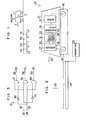
- FIG. 2 is a simplified side view showing an embodiment of an on-vehicle stopping position detecting system according to the invention.
- the stopping position detecting system for a vehicle 21 includes a transmitter 23, a single ground antenna 24, a plurality (two in the Figure) of vehicle antennas 25 and 26, and a receiver 27.
- the ground antenna 24 has a ground antenna length L 1 extending along a travel direction 28 of the vehicle 21 which travels along a vehicle track (not shown) and the ground antenna 24 is disposed in correspondence to a stopping position where the vehicle 21 makes a stop at a station or the like.
- the ground antenna 24 is connected to the transmitter 23.
- the transmitter 23 applies a stopping position indicative signal to the ground antenna 24.
- the ground antenna 24 generates a radio wave indicative of the stopping position in a circumferential direction 29 which is perpendicular to the travel direction 28.
- the vehicle antennas 25 and 26 are mounted on the vehicle 21 so as to provide a mounting interval L 2 in the travel direction 28.
- the mounting interval L 2 is selected Ll > L 2 .
- the vehicle antennas 25 and 26 are connected to the receiver 27.
- the receiver 27 can receive the radio wave from the ground antenna 24 only when the vehicle antennas 25 and 26 are positioned within the area of the ground antenna length L 1 .
- the output generated in dependence on the presence or absence of reception of the radio wave through the ground antenna 24 and the vehicle antenna 25 is applied to a discriminating circuit 31 from the receiver 27 via a line 30.
- the output corresponding to the presence or absence of reception of the radio wave through the ground antenna 24 and the vehicle antenna 26 is applied to the discriminating circuit 31 from the receiver 27 via a line 32.
- the discriminating circuit 31 makes a discrimination in accordance with the outputs from the receiver 27 through the lines 30 and 32 and the discrimination output is applied to a processing circuit 36 via a lines 33, 34 or 35.
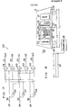
- Fig. 3 shows a specific circuit diagram of the discriminating circuit 31.
- the line 30, which receives an input signal SF, is connected to one input of AND gates 41 and 42, respectively, and it is also connected to one input of an AND gate 44 through an inverter circuit 43.
- the line 32, which receives an input signal SR, is connected to the other input of the AND gates 42 and 44, respectively, and it is also connected to the other input of the AND gate 41 through an inverter circuit 45.
- the output of the AND gate 41 is connected to the line 33 which delivers an output signal SS.
- the output of the AND gate 42 is connected to the line 34 which delivers an output signal SJ.
- the output of the AND gate 44 is connected to the line 35 which delivers an output signal S O .
- Table 2 shows the Boolean algebraic expressions and function tables for the outputs of the inverter circuits 45 and 43 and the AND gates 41, 42 and 44.
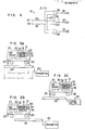
- Fig. 4 is another specific circuit diagram of the discriminating circuit 31.
- the line 30, which receives the input signal SF, is connected to one input of an AND gate 46 and one input of an AND gate 47, respectively.
- the line 32, which receives the input signal SR, is connected to the other input of the AND gate 47 and one input of an AND gate 48.
- the output of the AND gate 46 is connected to the line 33 which delivers the output signal SS.
- the output of the AND gate 47 is connected to the line 34 which delivers the output signal SJ and it is also connected to the other input of the AND gate 46 and the other input of the AND gate 48 through an inverter circuit 49.
- the output of the AND gate 48 is connected to the line 35 which delivers the output signal SO.
- Table 3 shows the Boolean algebraic expressions and function tables for the outputs of the inverter circuit 49 and the AND gates 46, 47 and 48.
- the processing circuit 36 is responsive to the discrimination output applied through the line 33, 34 or 35 to apply to a driving motor 37 the control signal for stopping the vehicle 21, moving the vehicle 21 in the travel direction 28 and then stopping it or moving the vehicle 21 in the opposite direction to the travel direction 28 and then stopping it.
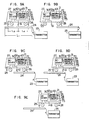
- the vehicle 21 is stopped at the just fixed position. Namely, assume a case where the vehicle 21 is stopped such that the vehicle antennas 25 and 26 are positioned within the area of the ground antenna length L 1 as shown in Fig. 5A.
- the receiver 27 receives the radio wave from the ground antenna 24 through the vehicle antenna 25 and generates a high level "1" signal on the line 32. Also the receiver 27 receives the radio wave from the ground antenna 24 via the vehicle antenna 26 and generates a high level "1" signal on the line 32. Since the lines 30 and 31 are both at the high level "1", the discriminating circuit 31 makes a discrimination of "just fixed position stopping" and only the line 34 is caused to to to the high level "1".
- the vehicle 21 is stopped to overrun the fixed position. Namely, assume a case where the vehicle 21 is stopped in such a manner that only the vehicle antenna 26 is positioned within the area of the ground antenna length Z1 as shown in Fig. 5B.
- the receiver 27 does not receive the wave from the ground antenna 24 via the vehicle antenna 25 and it generates a low level "0" signal on the line 30. Also, the receiver 27 receives the wave from the ground antenna 24 through the vehicle antenna 26 and thus it generates a high level "1" signal on the line 32.
- the discriminating circuit 31 makes a discrimination of "overrun stopping" and only the line 35 is caused to go to the high level "1".
- the vehicle 21 is stopped short of the fixed position. Namely, assume a case where the vehicle 21 is stopped so that only the vehicle antenna 25 is positioned within the area of the ground antenna length L 1 as shown in Fig. 5C.
- the receiver 27 receives the wave from the ground antenna 24 through the vehicle antenna 25 and thus a high level "1" signal is generated on the line 30. Also, the receiver 27 does not receive the wave from the ground antenna 24 through the vehicle antenna 26 and thus a low level "0" signal is generated on the line 32.
- the discriminating circuit 31 makes a discrimination of "short stopping" and consequently only the line 33 is caused to go to the high level "1".
- Table 4 shows the presence and absence of reception of radio waves of the receiver 27 from the ground antenna 24 through the vehicle antennas 25 and 26 or the reception conditions and the discriminations of the discriminting circuits 31 in the cases shown in Figs. 5A to 5C.
- Table 5 shows the fixed stopping position, the overrun stopping position and the short stopping position and their region lengths which are determined in accordance with the ground antenna length L 1 and the mounting interval L 2 of the vehicle antennas 25 and 26.
- the ground antenna length L 1 and the mounting interval L 2 can be selected arbitrarily within the range of L 1 ⁇ L 2 . Therefore, by changing the ground antenna length L 1 and the mounting interval L 2' it is possible to arbitrarily select the just fixed stopping position region, the overrun stopping position region and the short stopping position region. While, in Figs. 2 and 5, the vehicle antennas 25 and 26 are shown as arranged at near the ends of the vehicle 21 in the travel direction, it is possible to mount them at any other place such as near the central portion of the vehicle 21.
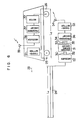
- F ig. 6 is a simplified side view showing an embodiment of a ground stopping position detecting : system according to the invention and the component parts corresponding to those of the embodiment shown in Fig. 2 are designated by the same reference numerals.
- a transmitter 51 applies to the vehicle antennas 25 and 26 signals which are different from each other, e.g., signals of different carriers.
- the ground antenna 24 is connected to a receiver 52.
- the receiver 52 discriminates whether the received radio wave is one from the vehicle antenna 25 or 26. Also, the receiver 52 generates an output on the line 30 in accordance with the presence or absence of the radio wave from the vehicle antenna 25 and it also generates an output on the line 32 in accordance with the presence or absence of the radio wave from the vehicle antenna 26.
- the output generated from the processing circuit 36 to control the driving motor 37 is delivered through a transmitter 53 and an antenna 54.
- the radio wave from the antenna 54 is applied to the motor 37 through an antenna 55, a receiver 56 and a processing circuit 57.
- the same discriminations as the embodiment shown in Fig. 2 are made and the motor 37 is controlled correspondingly.
- Table 6 shows the reception conditions of the receiver 52 from the vehicle antennas 25 and 26 through the ground antenna 24 and the discriminations of the discriminating circuit 31.
- the settings of the ground antenna length L l and the mounting interval L 2 are the same a those mentioned in connection with the embodiment of Fig. 2.
- F ig. 7 is a simplified side view showing another embodiment of the on-vehicle stopping position detecting system according to the invention and the component parts corresponding to those in the embodiments of Figs. 2 and 6 are designated by the same reference numerals.
- Another vehicle antenna 61 is arranged between the vehicle antennas 25 and 26 of the vehicle 21.
- These mounting intervals between the adjoining vehicle antennas 25, 61 and 26 are at most less than the ground antenna length L 1 (L 1 ⁇ L 3 , L 1 ⁇ L4).
- the receiver 27 applies a high level "1" signal or low level “0" signal to a precessing circuit 63 through a line 62 depending on whether or not the radio wave from the ground antenna 24 is received through the vehicle antenna 61.
- Fig. 8 shows a specific circuit diagram of the discriminating circuit 63.
- the line 30, which receives an input signal SF, is connected to an input of AND gates 64, 65 and 66, respectively, and to an input of AND gates 68 and 69, respectively, through an inverter circuit 67.
- the line 62, which receives an input signal SM, is connected to another input of the AND gates 65, 66 and 68, respectively, and it is also connected to another input of the AND gates 64 and 69, respectively, through an inverter circuit 70.
- the line 32 which receives an input signal SR, is connected to the other input of the AND gates 66, 68 and 69, respectively, and it is also connected to the other input of the AND gates 64 and 65, respectively, through an inverter circuit 71.
- the output-of the AND gate 64 is connected to a line 72 which delivers an output signal SLS.
- the output of the AND gate 65 is connected to the line 33 which delivers an output signal SS.
- the output of the AND gate 66 is connected to the line 34 which delivers an output signal SJ.
- the output of the AND gate 68 is connected to the line 35 which delivers an output signal SO.
- the output of the AND gate 69 is connected to a line 73 which delivers an output signal SLO.
- the lines 33, 34, 35, 72 and 73 are all connected to the processing circuit 36.
- Table 7 shows the Boolean algebraic expressions and function tables for the outputs of the inverter circuits 67, 70 and 71 and the AND gates 64, 65, 66, 68 and 69.
- the discrimination is effected in accordance with Table 7.
- the vehicle 21 is stopped at the just fixed position.
- the vehicle 21 is stopped in such a manner that the vehicle antennas 25, 61 and 26 are positioned within the area of the ground antenna length L 1 .
- the receiver 27 receives the radio wave from the ground antennas 24 through the vehicle antennas 25, 61 and 26 and thus the lines 30, 62 and 32 all go to the high level "1".
- the discriminating circuit 63 makes a discrimination of "just fixed position stopping" and only the line 34 is caused to go to the high level "1".
- the vehicle 21 is stopped to overrun greatly.
- the vehicle 21 is stopped in such a manner that only the vehicle antenna 26 is positioned within the area of the ground antenna length L 1 .
- the receiver 27 receives the wave from the ground antenna 24 only through the vehicle antenna 26 and thus only the line 32 is caused to go to the high level "1".
- the discriminating circuit 63 makes a discrimination of "long-overrun stopping" and only the line 73 is caused to go to the high level "1".
- the vehicle 21 is stopped to overrun the fixed position.
- the vehicle 21 is stopped in such a manner that the vehicle antennas 61 and 26 are positioned within the area of the ground antenna length L l .
- the receiver 27 receives the wave from the ground antenna 24 only through the vehicle antennas 61 and 26 and thus only the lines 62 and 32 are caused to go to the high level "1".
- the discriminating circuit 63 makes a discrimination of "overrun stopping" and only the line 35 is caused to go to the high level "1".
- the vehicle 21 is stopped short of the fixed position.
- the vehicle 21 is stopped in such a manner that the vehicle antennas 25 and 61 are positioned within the area of the ground antenna length L 1 .
- the receiver 27 receives the radio wave from the ground antenna 24 only through the vehicle antennas 25 and 61 and thus only the lines 30 and 62 are caused to go to the high level "1".
- the discriminating circuit 63 makes a discrimination of "short stopping" and only the line 33 is caused to go to the high level "1".
- the vehicle 21 is stopped greatly short of the fixed position.
- the vehicle 21 is stopped in such a manner that only the vehicle antenna 25 is positioned within the area of the ground antenna length L 1 .
- the receiver 27 receives the wave from the ground antenna 24 only through the vehicle antenna 25 and thus only the line 30 goes to the high level "1".
- the discriminating circuit 63 makes a discrimination of "long-short stopping" and only the line 72 goes to the high level "1".
- Table 8 shows the reception conditions of the receiver 27 through the vehicle antennas 25, 61 and 26 and the discriminations of discriminating circuit 63 in the cases shown in Figs. 9A to 9E.
- Table 9 shows the long-short stopping position, the short stopping position, the just fixed stopping position, the overrun stopping position and the long-overrun stopping position and their region lengths in accordance with the ground antenna length L 1 and the mounting intervals L 3 and L 4 .
- ground antenna length L1 and the mounting intervals L 3 and L 4 can be selected as desired within the range of L 1 ⁇ L 3 + L 4 .
- L 1 and the mounting intervals L 3 and L 4 it is possible to preset the long-short stopping position region, the short stopping position region, the just fixed stopping position region, the overrun stopping position region and the long-overrun stopping position region as desired.
- Fig. 10 is a simplified side view showing another embodiment of the ground stopping position detecting system according to the invention and the component parts corresponding to those of the embodiments shown in Figs. 2, 6 and 7 are designated by the same reference numerals.
- the mounting interval between the vehicle antennas 25 and 61 and the mounting interval between the vehicle antennas 61 and 26 are respectively set to L 3 and L 4 as in the embodiment of Fig. 7.
- the mounting intervals L 3 and L 4 are at most less than the ground antenna length L 1 (L 1 ⁇ L 3' L 1 ⁇ L 4 ) ' While two cases are conceivable in which the mounting interval L 2 is greater (L 2 ⁇ L 1 ) and smaller (L 2 ⁇ L 1 ) than the ground antenna length L 1 , a description will be made with reference to the latter case (L 2 ⁇ L 1 ).
- the transmitter 51 applies to the vehicle antenna 61 a signal which is different from those applied to the vehicle antennas 25 and 26.
- the receiver 52 discriminates whether the received wave is one from the vehicle antenna 61 and an output is generated on the line 62 in dependence on the presence of the wave from the vehicle antenna 61.
- the waves from the vehicle antenna 25, 61 and 26 through the ground antenna 24 are discriminated and received by the receiver 52 so that the same discriminations as in the embodiment shown in Fig. 7 are made and the motor 37 is controlled through the processing circuit 36, the transmitter 53, the antennas 54 and 55, the receiver 56 and the processing circuit 57 in the same manner as the previeously mentioned embodiments.
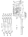
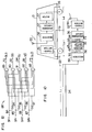
- Fig. 11 is a simplified side view showing another embodiment of the on-vehicle stopping position detecting system according to the invention and the component parts corresponding to those of the embodiments shown in Figs. 2, 6, 7 and 10 are designated by the same reference numerals.
- the vehicle antennas 25 and 26 of the mounting interval L 2 are mounted on the vehicle 21.
- the ground antenna 24 is divided into two sections, i.e., a ground antenna 81 of a ground antenna length L 5 and a ground antenna 82 of a ground antenna length L 6'
- L 1 L 5 + L 6 , L 2 ⁇ L 1 , L 5 ⁇ L 2 and L 6 ⁇ L 2 .
- Signals differing from each other are applied to the ground-antennas 81 and 82 from the transmitter 51.
- a receiver 83 causes a line 84 to go to the high level "1" only when the wave from the ground antenna 81 is received through the vehicle antenna 25. Also, the receiver 83 causes a line 85 to go to the high level "1” only when the wave from the ground antenna 82 is received through the vehicle antenna 25. Also, the receiver 83 causes a line 86 to go to the high level "1” only when the wave from the ground antenna 81 is received through the vehicle antenna 26. Also, the receiver 83 causes a line 87 to go to the high level "1” only when the wave from the ground antenna 82 is received through the vehicle antenna 26. The lines 84, 85, 86 and 87 are all connected to a discriminting circuit 88.
- a specific circuit diagram of the discriminating circuit 88 is shown in Fig. 12.
- the line 84 which receives an input signal SF f , is connected to an input of AND gates 90 and 91, respectively, and it is also connected to an input of AND gates 89, 92 and 93, respectively, through an inverter circuit 94.
- the line 85 which receives an input signal SF , is connected to another input of the AND gate 89 and to another input of the AND gates 90, 91, 92 and 93, respectively, through an inverter circuit 95.
- the line 86 which receives an input signal SR f , is connected to still another input of the AND gate 93 and to still another input of the AND gates 89, 90, 91 and 92, respectively, through an inverter circuit 96.
- the line 87 which receives an input signal SR , is connected to the other input of the AND gates 91 and 92, respectively, and it is also connected to the other input of the AND gates 90 and 93, respectively, through an inverter circuit 97.
- the output of the AND gate 89 is connected to the line 72 which delivers an output signal SLS.
- the output of the AND gate 90 is connected to the line 33 which delivers an output signal SS.
- the output of the AND gate 91 is connected to the line 34 which delivers an output signal SJ.
- the output of the AND gate 92 is connected to the line 35 which delivers an output signal SO.
- the output of the AND gate 93 is connected to the line 73 which delivers an output signal SLO.
- Table 10 shows the Boolean algebraic expressions and function tables for the outputs of the inverter circuits 94, 95, 96 and 97 and the AND gates 89, 90, 91, 92 and 93.
- the discrimination is effected in accordance with Table 10.
- the vehicle 21 is stopped at the just fixed position.
- the vehicle 21 is stopped in such a manner that the vehicle antenna 25 is positioned within the area of the ground antenna length L 5 and also the vehicle antenna 26 is positioned within the area of the ground antenna length L 6*
- the receiver 83 receives the wave from the ground antenna 81 only through the vehicle antenna 25 and it also receives the wave from the ground antenna 82 only through the vehicle antenna 26, thus causing only the lines 84 and 87 to go to the high level "1".
- the discriminating circuit 88 makes a discrimination of "just fixed position stopping" and only the line 34 is caused to go to the high level "1".
- the vehicle 21 is stopped to greatly overrun the fixed position.
- the vehicle 21 is stopped in such a manner that only the vehicle antenna 26 is positioned within the area of the ground antenna length L 5 .
- the receiver 83 receives the wave from the ground antenna 81 only through the vehicle antenna 26 and thus only the line 86 is caused to go to the high level "1".
- the discriminating circuit 88 makes a discrimination of "long-overrun stopping" and only the line 73 is caused to go to the high level "1".
- the vehicle 21 is stopped to overrun the fixed position.
- the vehicle 21 is stopped in such a manner that only the vehicle 26 is positioned within the area of the ground antenna length L 6 .
- the receiver 83 receives the wave from the ground antenna 82 only through the vehicle antenna 26 and thus only the line 87 is caused to go to the high level "1".
- the discriminating circuit 88 makes a discrimination of "overrun stopping" and only the line 35 is caused to to to the high level "1".
- the vehicle 21 is stopped short of the fixed position.
- the vehicle 21 is stopped in such a manner that only the vehicle antenna 25-is positioned within the area of the ground antenna length L 5'
- the receiver 83 receives the wave from the ground antenna 81 only through the vehicle antenna 25 and thus only the line 84 is caused to go to the high level "1".
- the discriminating circuit 88 makes a discrimination of "short stopping" and only the line 33 is caused to go to the high level "1".
- the vehicle 21 is positioned greatly short of the fixed position.
- the vehicle 21 is stopped in such a manner that only the vehicle antenna 25 is positioned within the area of the ground antenna length L 6*
- the receiver 83 receives the wave from the ground antenna 82 only through the vehicle antenna 25 and only the line 85 is caused to go to the high level "1".
- the discriminating circuit 88 makes a discrimination of "long-short stopping" and thus only the line 72 is caused to go to the high level "1".
- Table 11 shows the reception conditions of the receiver 83 from the ground antennas 81 and 82 through the vehicle antennas 25 and 26 and the discriminations of the discriminating circuit 88.
- Table 12 shows the long-short stopping position, the short stopping position, the just fixed stopping position, the overrun stopping position and the long-overrun stopping position and their region length in accordance with the ground antenna lengths L 5 and L 6 and the mounting interval L 2 .
- the stopping position information will be increased with an increase in the number of divisions of the ground antenna and a fine detailed setting of stopping position regions is ensured.
- the ground antenna lengths L 5 and L 6 and the mounting interval L 2 can be selected as desired within the previously mentioned ranges. Therefore, the long-short stopping position region, the short stopping position region, the just fixed stopping position region, the overrun stopping position region and the long-overrun stopping position region can be preset as desired by suitably changing the ground antenna lengths L 5 and L 6 and the mounting interval L 2 .
- the same signal may be applied to the ground antennas 81 and 82 from the transmitter 51.
- the ground antennas 81 and 82 become effectively equal to the single ground antenna 24. Therefore, it is only necessary to replace the receiver 83 and the discriminating circuit 88 with the receiver 27 and the discriminating circuit 31 as in the embodiment shown in Fig. 2.
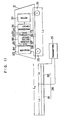
- Fig. 14 is a simplified side view showing another embodiment of the ground stopping position detecting system according to the invention and the component parts corresponding to those in the embodiments of Figs. 2, 6, 7, 10 and 11 are designated by the same reference numerals.
- This embodiment can be considered in correspondence to the on-vehicle stopping position detecting system shown in Fig. 11 and therefore the discrimination is made in the same manner as the on-vehicle stopping position detecting system of Fig. 11 thereby controlling the motor 37.
- Fig. 15 is a simplified side view showing another embodiment of the invention and the component parts corresponding to those in the embodiments of Figs. 2, 6, 7, 10, 11 and 14 are designated by the same reference numerals.
- this embodiment is the use of the two divided ground antennas 81 and 82 and the three vehicle antennas 25, 61 and 26. With this embodiment, both the on-vehicle stopping position detecting system and the ground stopping position detecting system can be accomplished so as to perform the same discrimination and control as mentioned previously.
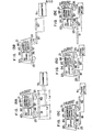
- Fig. 16 is a simplified side view showing another embodiment of the on-vehicle detecting system according to the invention and the component parts corresponding to those in the embodiments of Figs. 2, 6, 7, 10, 11, 14 and 15 are designated by the same reference numerals.
- a discriminating circuit 100 is constructed as shown in Fig. 17.
- the line 30, which receives an input signal SF, is connected to an input of AND gates 101 and 102, respectively, and it is also connected to an input of AND gates 103, 104 and 105, respectively, through an inverter circuit 106.
- the line 62, which receives an input signal SM, is . connected to another input of the AND gates 102, 103 and 104, respectively, and it is also connected to another input of the AND gates 101 and 105, respectively, through an inverter circuit 107.
- the line 32, which receives an input signal SR, is connected to the other input of the AND gates 104 and 105, respectively, and it is also connected to the other input of the AND gates 101, 102 and 103, respectively, through an inverter circuit 108.
- the output of the AND gate 101 is connected to the line 72 which delivers an output signal SLS.
- the output of the AND gate 102 is connected to the line 33 which delivers an output signal SS.
- the output of the AND gate 103 is connected to the line 34 which delivers an output signal SJ.
- the output of the AND gate 104 is connected to the line 35 which delivers- an output signal SO.
- the output of the AND gate 105 is connected to the line 73 which delivers an output signal SLO.
- Table 13 shows the Boolean algebraic expressions and function tables for the outputs of the inverter circuits 106, 107 and 108 and the AND gates 101, 102, 103, 104 and 105.
- the discrimination is effected in accordance with Table 13.
- the discriminating circuit 100 makes a discrimination of "long-short stopping" and only the line 72 is caused to go to the high level "1".
- the discriminating circuit 100 makes a discrimination of "short stopping" and thus only the line 33 goes to the high level "1".
- the discriminating circuit 100 makes a discrimination of "just fixed position stopping" and thus only the line 34 goes to the high level "1".
- the discriminating circuit 100 makes a discrimination of "overrun stopping" and thus only the line 35 goes to the high level "1".
- the discriminating circuit 100 makes a discrimination of "long-overrun stopping" and thus only the line 73 goes to the high level "1".
- Table 14 shows the reception conditions of the receiver 27 from the ground antenna 24 through the vehicle antennas 25, 61 and 26 and the discriminations of the discriminating circuit 100 in the above-mentioned cases.
- Table 15 shows the long-short stopping position, the short stopping position, the just fixed stopping position, the overrun stopping position and the long-overrun stopping position and their region lengths in accordance with the ground antenna length L 1 and the mounting intervals L 3 and L 4 .
- the ground antenna length L 1 and the mounting intervals L 2 , L 3 and L 4 can be preset as desired within the above-mentioned ranges.
- the long-short stopping position region, the short stopping position region, the just fixed stopping position region, the overrun stopping position region and the long-overrun stopping position region can be preset as desired by suitably changing the ground antenna length L 1 and the mounting intervals L 3 and L 4 .
- the discrimination is effected while the vehicle is at stopped condition
- the discrimination can of course be effected while the vehicle is running.
- the ground antenna may be divided into any other plurality of sections than previously. Also, any other plurality of vehicle antennas than previously may be mounted on the vehicle. Also, the output of the receiver may be applied to the processing circuit without passing through the discriminating circuit. Further, the ground antenna 24 may be arranged along the entire length of the vehicle track.
- a ground antenna which is undivided or divided into a plurality of sections, is arranged over a predetermined distance to extend along the direction of travel of a vehicle in correspondence to a stopping position where the vehicle is to stop and a plurality of vehicle antennas are mounted on the vehicle such that the interval between the adjacent vehicle antennas in the travel direction is at most less than the predetermined distance whereby the radio waves from the ground antennas are received by the vehicle antennas or the waves from the vehicle antennas are received by the ground antennas within the area of the predetermined distance and the stopped position is discriminated in accordance with the manner of receiving, it is possible to prevent the occurrence of any erroneous discrimination due to the rocking or the like of the vehicle and to accurately detect the stopping position where the vehicle is to stop. Further, the discrimination is effected even during the time that the vehicle is at stopped condition and therefore the stopping position can be accurately detected even after the recovery of the power supply.
Landscapes
- Engineering & Computer Science (AREA)
- Physics & Mathematics (AREA)
- General Physics & Mathematics (AREA)
- Aviation & Aerospace Engineering (AREA)
- Radar, Positioning & Navigation (AREA)
- Remote Sensing (AREA)
- Electromagnetism (AREA)
- Automation & Control Theory (AREA)
- Mechanical Engineering (AREA)
- Train Traffic Observation, Control, And Security (AREA)
- Traffic Control Systems (AREA)
- Platform Screen Doors And Railroad Systems (AREA)
- Electric Propulsion And Braking For Vehicles (AREA)
Applications Claiming Priority (2)
| Application Number | Priority Date | Filing Date | Title |
|---|---|---|---|
| JP143000/82 | 1982-08-17 | ||
| JP57143000A JPS5932008A (ja) | 1982-08-17 | 1982-08-17 | 車両の停止位置検出方式 |
Publications (3)
| Publication Number | Publication Date |
|---|---|
| EP0102017A2 true EP0102017A2 (de) | 1984-03-07 |
| EP0102017A3 EP0102017A3 (en) | 1987-06-03 |
| EP0102017B1 EP0102017B1 (de) | 1991-01-16 |
Family
ID=15328606
Family Applications (1)
| Application Number | Title | Priority Date | Filing Date |
|---|---|---|---|
| EP83108008A Expired EP0102017B1 (de) | 1982-08-17 | 1983-08-12 | Anlage zur Feststellung des Haltepunktes eines Fahrzeuges |
Country Status (3)
| Country | Link |
|---|---|
| EP (1) | EP0102017B1 (de) |
| JP (1) | JPS5932008A (de) |
| DE (1) | DE3382118D1 (de) |
Cited By (1)
| Publication number | Priority date | Publication date | Assignee | Title |
|---|---|---|---|---|
| USRE39011E1 (en) | 1994-03-31 | 2006-03-14 | Cattron Intellectual Property Corporation | Remote control system for a locomotive |
Families Citing this family (8)
| Publication number | Priority date | Publication date | Assignee | Title |
|---|---|---|---|---|
| JP4646833B2 (ja) * | 2006-03-06 | 2011-03-09 | 株式会社京三製作所 | 情報伝送装置 |
| JP5235754B2 (ja) * | 2009-03-31 | 2013-07-10 | 大同信号株式会社 | 停車場内列車停止位置合否判定システム |
| CN102897194B (zh) * | 2011-07-26 | 2015-05-20 | 上海工程技术大学 | 一种城市轨道交通检修小车定位信息处理方法 |
| CN102897195B (zh) * | 2011-07-26 | 2015-05-20 | 上海工程技术大学 | 一种城市轨道交通检修小车定位系统 |
| CN102951188B (zh) * | 2011-08-22 | 2017-04-12 | 铁道部信息技术中心 | 一种铁路调度命令平台系统 |
| CN102951187B (zh) * | 2011-08-22 | 2015-08-26 | 铁道部信息技术中心 | 一种铁路生产指挥平台系统及编制阶段调整计划的方法 |
| CN102627116B (zh) * | 2012-04-25 | 2014-10-29 | 湖南贯日科技有限公司 | 电机车闯红灯柔性拦截系统 |
| CN102963395B (zh) * | 2012-12-11 | 2015-03-04 | 南京泰通科技有限公司 | 一种实时监控的铁路半自动闭塞信息系统及其工作方法 |
Family Cites Families (5)
| Publication number | Priority date | Publication date | Assignee | Title |
|---|---|---|---|---|
| GB1390225A (en) * | 1972-06-14 | 1975-04-09 | British Railways Board | Vehicle control system |
| US3813538A (en) * | 1972-10-04 | 1974-05-28 | Bendix Corp | System for automatically controlling a land vehicle |
| US3958783A (en) * | 1973-06-15 | 1976-05-15 | Westinghouse Electric Corporation | Vehicle zero speed detection system |
| JPS5037154A (de) * | 1973-08-09 | 1975-04-07 | ||
| JPS6016644B2 (ja) * | 1978-07-12 | 1985-04-26 | 株式会社日立国際電気 | 移動体の停止位置自己検知装置 |
-
1982
- 1982-08-17 JP JP57143000A patent/JPS5932008A/ja active Pending
-
1983
- 1983-08-12 EP EP83108008A patent/EP0102017B1/de not_active Expired
- 1983-08-12 DE DE8383108008T patent/DE3382118D1/de not_active Expired - Lifetime
Cited By (3)
| Publication number | Priority date | Publication date | Assignee | Title |
|---|---|---|---|---|
| USRE39011E1 (en) | 1994-03-31 | 2006-03-14 | Cattron Intellectual Property Corporation | Remote control system for a locomotive |
| USRE39210E1 (en) | 1994-03-31 | 2006-08-01 | Cattron Intellectual Property Corporation | Remote control system for a locomotive |
| USRE39758E1 (en) | 1994-03-31 | 2007-08-07 | Cattron Intellectual Property Corporation | Remote control system for a locomotive |
Also Published As
| Publication number | Publication date |
|---|---|
| EP0102017B1 (de) | 1991-01-16 |
| DE3382118D1 (de) | 1991-02-21 |
| JPS5932008A (ja) | 1984-02-21 |
| EP0102017A3 (en) | 1987-06-03 |
Similar Documents
| Publication | Publication Date | Title |
|---|---|---|
| EP0102017A2 (de) | Anlage zur Feststellung des Haltepunktes eines Fahrzeuges | |
| US6377205B1 (en) | Method and device for classifying overhead objects | |
| US6992613B2 (en) | Object detecting device | |
| EP0146851A2 (de) | System und Verfahren zur automatischen Fahrzeuggeschwindigkeitssteuerung | |
| EP0715185A2 (de) | Verfahren und Vorrichtung zum Entdecken von Antwortgeräten | |
| US3694751A (en) | Induction radio transmission system | |
| KR960019025A (ko) | 이동체 특정 장치 | |
| US4433324A (en) | Device to promote the movement of buses by allocation of priority of crossing of an intersection controlled by traffic lights | |
| KR960039484A (ko) | 노차간 통신 방법 및 장치 | |
| US4332032A (en) | Adaptive hybrid antenna system | |
| GB1497917A (en) | Vehicle identification system | |
| EP0485879A2 (de) | Verfahren und Ortungseinrichtung zur Ortung von Fahrzeugen fahrerloser Transportsysteme | |
| KR930023895A (ko) | 수동 응답기가 장착된 차량통과 검출시스템 | |
| US4331959A (en) | Method and apparatus for detecting a defective object on a lane or track | |
| DE69728007T2 (de) | Nachrichtenempfangssystem und dazugehöriges Steuerverfahren | |
| KR100196709B1 (ko) | 이동체의 추돌방지장치 | |
| JP4011204B2 (ja) | 踏切制御システム | |
| JP2761709B2 (ja) | 移動体の追突防止装置 | |
| JPH06255487A (ja) | 金属検知装置 | |
| JPH06171509A (ja) | 車上装置 | |
| JP2706999B2 (ja) | 無人搬送車の走行制御方法 | |
| JP2024034509A (ja) | 列車位置検知装置および列車位置検知方法 | |
| SU690524A1 (ru) | Устройство дл приема и передачи информации с контрольного пункта | |
| GB1468272A (en) | Perimeter surveillance system | |
| JP2538860B2 (ja) | 車両の位置検知装置 |
Legal Events
| Date | Code | Title | Description |
|---|---|---|---|
| PUAI | Public reference made under article 153(3) epc to a published international application that has entered the european phase |
Free format text: ORIGINAL CODE: 0009012 |
|
| AK | Designated contracting states |
Designated state(s): DE FR |
|
| PUAL | Search report despatched |
Free format text: ORIGINAL CODE: 0009013 |
|
| AK | Designated contracting states |
Kind code of ref document: A3 Designated state(s): DE FR |
|
| 17P | Request for examination filed |
Effective date: 19870821 |
|
| 17Q | First examination report despatched |
Effective date: 19881207 |
|
| GRAA | (expected) grant |
Free format text: ORIGINAL CODE: 0009210 |
|
| AK | Designated contracting states |
Kind code of ref document: B1 Designated state(s): DE FR |
|
| REF | Corresponds to: |
Ref document number: 3382118 Country of ref document: DE Date of ref document: 19910221 |
|
| ET | Fr: translation filed | ||
| PLBE | No opposition filed within time limit |
Free format text: ORIGINAL CODE: 0009261 |
|
| STAA | Information on the status of an ep patent application or granted ep patent |
Free format text: STATUS: NO OPPOSITION FILED WITHIN TIME LIMIT |
|
| 26N | No opposition filed | ||
| PGFP | Annual fee paid to national office [announced via postgrant information from national office to epo] |
Ref country code: DE Payment date: 19921029 Year of fee payment: 10 |
|
| PGFP | Annual fee paid to national office [announced via postgrant information from national office to epo] |
Ref country code: FR Payment date: 19930831 Year of fee payment: 11 |
|
| PG25 | Lapsed in a contracting state [announced via postgrant information from national office to epo] |
Ref country code: DE Effective date: 19940503 |
|
| PG25 | Lapsed in a contracting state [announced via postgrant information from national office to epo] |
Ref country code: FR Effective date: 19950428 |
|
| REG | Reference to a national code |
Ref country code: FR Ref legal event code: ST |