EP0101745A1 - Compresseur rotatif - Google Patents
Compresseur rotatif Download PDFInfo
- Publication number
- EP0101745A1 EP0101745A1 EP83900803A EP83900803A EP0101745A1 EP 0101745 A1 EP0101745 A1 EP 0101745A1 EP 83900803 A EP83900803 A EP 83900803A EP 83900803 A EP83900803 A EP 83900803A EP 0101745 A1 EP0101745 A1 EP 0101745A1
- Authority
- EP
- European Patent Office
- Prior art keywords
- suction
- vanes
- rotor
- compressor
- cylinder
- Prior art date
- Legal status (The legal status is an assumption and is not a legal conclusion. Google has not performed a legal analysis and makes no representation as to the accuracy of the status listed.)
- Granted
Links
Images


Classifications
-
- F—MECHANICAL ENGINEERING; LIGHTING; HEATING; WEAPONS; BLASTING
- F04—POSITIVE - DISPLACEMENT MACHINES FOR LIQUIDS; PUMPS FOR LIQUIDS OR ELASTIC FLUIDS
- F04C—ROTARY-PISTON, OR OSCILLATING-PISTON, POSITIVE-DISPLACEMENT MACHINES FOR LIQUIDS; ROTARY-PISTON, OR OSCILLATING-PISTON, POSITIVE-DISPLACEMENT PUMPS
- F04C29/00—Component parts, details or accessories of pumps or pumping installations, not provided for in groups F04C18/00 - F04C28/00
- F04C29/12—Arrangements for admission or discharge of the working fluid, e.g. constructional features of the inlet or outlet
-
- F—MECHANICAL ENGINEERING; LIGHTING; HEATING; WEAPONS; BLASTING
- F04—POSITIVE - DISPLACEMENT MACHINES FOR LIQUIDS; PUMPS FOR LIQUIDS OR ELASTIC FLUIDS
- F04C—ROTARY-PISTON, OR OSCILLATING-PISTON, POSITIVE-DISPLACEMENT MACHINES FOR LIQUIDS; ROTARY-PISTON, OR OSCILLATING-PISTON, POSITIVE-DISPLACEMENT PUMPS
- F04C28/00—Control of, monitoring of, or safety arrangements for, pumps or pumping installations specially adapted for elastic fluids
- F04C28/18—Control of, monitoring of, or safety arrangements for, pumps or pumping installations specially adapted for elastic fluids characterised by varying the volume of the working chamber
Definitions
- This invention relates to a rotary compressor for car air conditioning which has, for example, vanes and changes the number of rotation in a wide range.
- a sliding vane type compressor as shown in Fig. 1, comprises a cylinder 1 having therein a cylindrical space, the side surfaces (not shown in Fig. 1) fixed to both sides of the cylinder 1 and sealing blade chambers 2a and 2b of the inner space in the cylinder 1, a rotor 3 disposed at the center thereof, and vanes 5 slidably engageable with grooves 4 provided at the rotor 3, suction bores 6a and 6b, being formed at the cylinder 1, discharge bores 7a and 7b being formed at the same, communication conduits 8a and 8b communicating with the blade chambers 2a and 2b formed in the cylinder 1, and set screws 9a and 9b at the suction side and those 10a and 10b at the discharge side being provided.
- vanes 5 project outwardly by a centrifugal force as the rotor 3 rotates so that the utmost ends of vanes 5 slidably move along the inner periphery of cylinder 1, thereby prevent leakage of gas from the compressor.
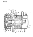
- Fig. 2 is a sectional side view of the compressor, in which reference numeral 11 designates a front plate of side plate, 12 designates a rear plate, 13 designates a front casing, 14 designates a rotary shaft, 15 designates a shell, 16 designates an annular suction conduit formed between the front casing 13 and the front plate 11, 17 designates a suction piping joint, 18 designates a suction conduit shown by the chain line, 19 designates a disc for clutch means, and 20 designate a pulley for clutch means.
- reference numeral 11 designates a front plate of side plate
- 12 designates a rear plate
- 13 designates a front casing
- 14 designates a rotary shaft
- 15 designates a shell
- 16 designates an annular suction conduit formed between the front casing 13 and the front plate 11
- 17 designates a suction piping joint
- 18 designates a suction conduit shown by the chain line
- 19 designates a disc for clutch means
- 20 designate a pull
- the compressor as shown in Fig. 1, having the cylinder 1 not-circular in the inner surface in section requires a plurality of pairs of suction bores and discharge bores.
- the compressor having a cylinder of the inner surface about elliptic in section discharges a refrigerant compressed in the right-hand and left-hand blade chambers 2a and 2b through two discharge bores 7a and 7b into a common space formed of cylinder 1 and shell 15.
- annular suction conduit 16 communicating in common with two suction bores 6a and 6b and the piping joint 17 provided at the front casing 13 connects the conduit 16 with an external refrigerant supply source (an exit of an evaporator).
- Such construction need only provide each one suction and piping joint even in a multirobe type compressor having two or more cylinder chambers.
- Such sliding vane type rotary compressor can be small- sized and simple in construction rather than the reciprocating compressor complex in construction and of many parts, thereby having recently been used for the - car cooler compressor.
- the rotary compressor has the following problems in comparison with the reciprocating compressor.
- a control valve for changing an opening area of communicating conduit is provided at the conduit communicating with the suction bores 6a and 6b at the rotary compressor, the opening area being restricted during the high speed rotation to utilize the suction loss for performing capacity control.
- the control valve should extra be attached, thereby having created the problem in that the compressor is complex in construction and expensive to produce.
- Another method, which uses a fluid clutch or planetary gears not to increase the number of rotations more than the predetermined value has hitherto been proposed for eliminating the excessive capacity of compressor during the high speed driving.
- the former method is larger in energy loss caused by friction heating on the relative-moving surface and the latter is added with a planetary gear mechanism of many parts to be larger in size and configuration, thereby being difficult to put in practical use because the tendency of energy saving recently increasingly requires simplification and miniaturization of compressor.
- This invention has expanded application of the above to a general compressor.
- this invention has designed a concrete construction of compressor comprising a not-circular cylinder when subjected to capacity control.
- An object of the invention is to provide a compressor having two laterally symmetrical chambers (two robes) in a space formed by a rotor and an elliptic cylinder, providing at least four or more vanes disposed separately within the rotor, and forming the suction ports and suction grooves so that the effective suction area changes in about two stages during the suction stroke, thereby operating the compressor with low torque without lowering the refrigerating capacity during the low speed driving and obtaining an effective suppression effect during the high speed driving.
- the compressor of the invention comprises a rotor, vanes contained slidably therein, a not-circular cylinder containing therein the rotor, side plates fixed to both sides of cylinder and sealing spaces in blade chambers formed of the vanes, rotor and cylinder at both sides of blade chamber, suction bores, and discharge bores, thereby utilizing a suction loss caused by pressure within the blade chamber lower than that of refrigerant supply source during the suction stroke so as to suppress the refrigerating capacity of the compressor during the high speed driving, and is characterized in that an effective area of each passage from the suction bore to the blade chamber is adapted to change in at least two stages to thereby be made smaller in the second half of the suction stroke than in the first half of the same.
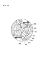
- Fig. 3 is a sectional front view of an embodiment of a compressor of the invention, in which reference numeral 50 designates a cylinder, 51A designates a blade chamber A, 51B designates a blade chamber B, 52 designates vanes disposed into a rotor 53 spaced circumferentially thereof at five equal intervals, 54A and 54B designate suction bores, 55A and 55B designate suction nozzles, 56A and 56B designate suction grooves formed at the inner periphery of cylinder 50, 57A and 57B designate discharge bores, 58A and 58B designate discharge valve holders, 59A and 59B designate fixing bolts at the suction side, 60A and 60B designate fixing bolts at the discharge side, and 61A and 61B designate cutouts formed at the positions where the suction side and discharge side are separate laterally from each other.
- reference numeral 50 designates a cylinder
- 51A designates a blade chamber A
- 51B designates a
- a sliding vane compressor comprising a cylinder other than the round one is to be hereinafter called the multirobe type compressor.
- Fig. 4-(b) shows a condition just before the termination of suction stroke, in which the refrigerant is supplied to the downstream side blade chamber 62a from between the vane 64b and the suction groove 56A.
- the port position angle 8 2 represents an angle between the top portion 70A at the cylinder 50 and the center of suction port 54A, the travelling angle ⁇ 1 of the cylinder groove in the control zone representing an angle of travelling of vane 64b along the suction 56A until the suction stroke terminates.
- the multi- robe type compressor is used to change step the effective suction area during the suction stroke, thereby having enabled realization of the compressor which is operable at low speed, is less in volumetric efficiency loss, saves power consumption, and has an effective suppression effect on the refrigerating capacity during the high speed driving only.
- the multi-robe type compressor is smaller in total weight of refrigerant allotted to one blade chamber in comparison with the compressor of round cylinder, thereby being advantageous in the high speed durability with respect to fluid compression or excess compression. It will be detailed in Item (II) why the stepped change of suction area makes effective the capacity control characteristic, but nextly, the compressor of multi-robe type of three vanes and four vanes will be compared with that of the aforesaid five vanes in the following description.
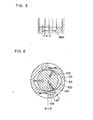
- Fig. 6 shows a construction of the three vane compressor, in which reference numeral 100 designates a rotor, 101 designates a cylinder, 102 designates a suction port, 103 designates a vane a, 104 designates a vane b, and 105 designates a blade chamber A.
- a travelling angle ⁇ 1 of vane b 104 following the vane a 103 is only 8.6° with respect to the cylinder groove, thereby being difficult to construct the effective suction area in a stepped manner during the suction stroke.
- Fig. 7 shows a construction of the four vane compressor, in which reference numeral 200 designates a rotor, 201 designates a cylinder, 202 designates a suction port, 202a designates a vane a, 203 designates a vane b, and 204 designates a blade chamber A.
- Fig. 8 shows a pattern of effective suction area obtainable by the respective compressors different in numbers of vanes.
- Fig. 9 and Table 2 show in the patterns (a) to (f) the effective suction area a with respect to the travelling angle of vane, where the effective suction area has been arranged by the capacity control parameter K 2 in order to carry out relative comparison of characteristics of various compressors (K 2 is to be discussed below).
- the patterns (b) to (f) shows the effective suction area made larger in the first half of suction stroke and smaller in the second half ofthe same.
- the patterns (b) to (g) corresponds to the present invention aiming at reducing torque during the low speed driving.
- the transient characteristic of pressure in the blade chamber is given by the following energy equation: where G: mass flow of refrigerant, Va: blade chamber volume, A: thermal equivalent of work, Cp: specific heat at constant pressure, T A : refrigerant temperature at the supply side, k: ratio of specific heat, R: gas constant, C V : specific heat in constant volume, Pa: pressure in blade chamber, Q: quantity of heat, y a : specific weight of refrigerant in blade chamber, and Ta: refrigerant temperature in blade chamber.
- G mass flow of refrigerant
- Va blade chamber volume
- A thermal equivalent of work
- Cp specific heat at constant pressure
- T A refrigerant temperature at the supply side
- k ratio of specific heat
- R gas constant
- C V specific heat in constant volume
- Pa pressure in blade chamber
- Q quantity of heat
- y a specific weight of refrigerant in blade chamber
- Ta refrigerant temperature in blade chamber.
- the first term at the left side represents the thermal energy of refrigerant taken into the blade chamber through the suction bore at the unit time
- the second term at the same represents work of refrigerant pressure with respect to the exterior at the unit time
- the third term at the same represents thermal energy flowing into the blade chamber from the exterior through the outer wall
- the right side represents an increment in the internal energy of system at the unit time.
- a mass flow of refrigerant passing through the suction bore is applicable with the theory of nozzle, whereby the equation: is obtained. Therefore, the equations (3) and (4) are solved to obtain the transient characteristic of pressure Pa in the blade chamber.
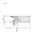
- Fig. 10 shows the transient characteristics of pressure in the blade chamber in a case of the effective suction area (c) in Fig. 9 obtained by using the number of rotations as the parameter.
- np the pressure drop rate
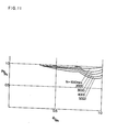
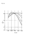
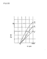
- Fig. 13 is a graph showing a characteristic of the pressure drop rate with respect to the number of rotations when the effective suction areas are different respectively (in Figs. 9-(a) to -(f)). Namely,
- the pressure drop rate may be considered to be about equal to that for the gross weight of refrigerant filled in the blade chamber at the termination of suction stroke. Accordingly, the compressor having the pressure drop rate with respect to the number of rotations of the characteristic as shown in Fig. 13-(c), even when viewed from the control amount only of refrigerant, is known to obtain the refrigerating capacity nearly conforming to the ideal one as follows:
- the reciprocating compressor of self suppression effect for the refrigerating capacity is characterized in that its suction loss is minimum at low speed rotation, but the rotary compressor of the invention has the characteristic not inferior to the reciprocating one.
- the rotary compressor obtains the refrigerating capacity suppressing effect equal to or more than that of conventional reciprocating compressor.
- the embodiment of the present invention is characterized, besides the above effects in Items i to iii, in that the multi-robe type compressor of not-circular cylinder, even when used, can obtain lower power consumption at the low speed rotation.
- the drive torque of compressor includes the following items: .
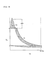
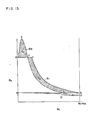
- a curve N 1 described by a, b, c and d shows a standard polytropic suction compression stroke.
- a curve N 2 described a, b', e, g and d applies the capacity control, the curves N 1 and N 2 showing the effective suction area constant during the suction stroke, for example, the PV chart of effective area in Fig. 9-(a).
- the pressure Pa in the blade chamber at the beginning point of compression stroke lowers as the number of rotations increases.
- a curve N 3 corresponds to the PV chart in Figs. 9-(b) to (f) where the effective suction area is two-stepped, in which an area S l : power loss in the suction stroke, that_S 2 : decrement of compression power by the capacity control effect, and that 8 3 : loss of excessive compression power.
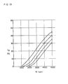
- Figs. 17 and 18 show the suction loss and excessive compression loss of the respective items (a) to (f) with respect to the number of rotations, from which it is seen that the smaller the effective suction area during the suction stroke is, the larger the suction loss becomes, and reversely the excessive compression loss becomes larger.
- the effective suction area is made stepped to enable the rotor to rotate at low torque and low speed keeping moderate the capacity control effect.
- the stepped construction of effective suction area, as abovementioned, is difficult for the three vane type, whereby the embodiment of five vanes is the best.
- the embodiment of four to five vanes was proper because the number of vanes increased more than the need has increased a mechanical sliding loss between the vane and the cylinder.
- volume Va of blade chamber is the function of rotor diameter Rr or the cylinder configuration or the like, so that a method will be proposed which uses the following approximate functions to arrange the equations (3) and (4) to catch the correlation between the respective parameters and the capacity control effect.
- Va ( ⁇ ) Vo ⁇ f( ⁇ )...(6).
- a ratio of specific heat in the equation (10) is the constant depending only on the kind of refrigerant.
- the effective suction area a is the function of vane travelling angle ⁇ of the dimensionless quantity, whereby the parameter K l also becomes the function of ⁇ .
- R and T A in the equation (13) are set not by the construction of compressor, but under the same conditions, whereby the capacity control parameter can be re-defined as follows:
- K 2 1 and K 22 are defined as follows by use of the effective suction areas a l and a 2 in the first half of suction stroke and in the second half of the same respectively:
- the effective area in the first half of suction stroke in other words, the parameter K 22 in the second half is included between (a) and (f) in a practical range as
- N 2 1800 to 2200 rpm.
- the effective suction area is obtained from the product of sectional area depending on a geometric configuration of suction passage and coefficient of contraction.
- the embodiment of the compressor of the invention could be constructed to simultaneously satisfy the equations 17 and 19 and sufficiently obtain the capacity control in low torque during the low speed driving and also even at the high speed driving.
- FIG. 22 A modified embodiment of the invention is shown in Fig. 22, in which reference numeral 300 designates a rotor, 301 designates a cylinder, 302 designates vanes, 303 designates suction bores, 304 designates suction grooves, 305 designates set screws at the suction side, 306 designates set screws at the discharge side, and 307 designates suction nozzles.
- the multi-robe type compressor having the effective suction area applied with the stepped change has been proposed of its construction. It is effective for leakage of refrigerant from the high pressure ride into the blade chamber during the suction stroke to enlarge the effective suction area in the first half, thereby largely contributing to an improvement in the volumetric efficiency during the low speed driving.
Landscapes
- Engineering & Computer Science (AREA)
- Mechanical Engineering (AREA)
- General Engineering & Computer Science (AREA)
- Rotary Pumps (AREA)
Abstract
Applications Claiming Priority (4)
| Application Number | Priority Date | Filing Date | Title |
|---|---|---|---|
| JP3482382A JPS58152191A (ja) | 1982-03-04 | 1982-03-04 | 圧縮機 |
| JP34823/82 | 1982-03-04 | ||
| JP46666/82 | 1982-03-23 | ||
| JP4666682A JPS58162789A (ja) | 1982-03-23 | 1982-03-23 | 圧縮機 |
Publications (3)
| Publication Number | Publication Date |
|---|---|
| EP0101745A1 true EP0101745A1 (fr) | 1984-03-07 |
| EP0101745A4 EP0101745A4 (fr) | 1984-07-18 |
| EP0101745B1 EP0101745B1 (fr) | 1987-05-20 |
Family
ID=26373676
Family Applications (1)
| Application Number | Title | Priority Date | Filing Date |
|---|---|---|---|
| EP83900803A Expired EP0101745B1 (fr) | 1982-03-04 | 1983-03-03 | Compresseur rotatif |
Country Status (4)
| Country | Link |
|---|---|
| US (1) | US4536141A (fr) |
| EP (1) | EP0101745B1 (fr) |
| DE (1) | DE3371675D1 (fr) |
| WO (1) | WO1983003123A1 (fr) |
Cited By (1)
| Publication number | Priority date | Publication date | Assignee | Title |
|---|---|---|---|---|
| CN110546384A (zh) * | 2017-04-28 | 2019-12-06 | 株式会社三国 | 叶片泵 |
Families Citing this family (5)
| Publication number | Priority date | Publication date | Assignee | Title |
|---|---|---|---|---|
| US4789317A (en) * | 1987-04-23 | 1988-12-06 | Carrier Corporation | Rotary vane oil pump and method of operating |
| JPH02125992A (ja) * | 1988-11-04 | 1990-05-14 | Diesel Kiki Co Ltd | 圧縮機 |
| US9267504B2 (en) | 2010-08-30 | 2016-02-23 | Hicor Technologies, Inc. | Compressor with liquid injection cooling |
| US8794941B2 (en) | 2010-08-30 | 2014-08-05 | Oscomp Systems Inc. | Compressor with liquid injection cooling |
| CN109538478A (zh) * | 2018-11-27 | 2019-03-29 | 王廷华 | 一种压缩机 |
Citations (5)
| Publication number | Priority date | Publication date | Assignee | Title |
|---|---|---|---|---|
| DE884683C (de) * | 1951-07-31 | 1953-07-30 | Werner Rietschle | Drehkolbengeblaese |
| JPS5155411U (fr) * | 1974-10-28 | 1976-04-28 | ||
| GB1501474A (en) * | 1975-07-16 | 1978-02-15 | Uniscrew Ltd | Rotary compressors |
| EP0049030A1 (fr) * | 1980-09-25 | 1982-04-07 | Matsushita Electric Industrial Co., Ltd. | Compresseur rotatif à palettes coulissantes |
| EP0064356A1 (fr) * | 1981-04-24 | 1982-11-10 | Matsushita Electric Industrial Co., Ltd. | Compresseur |
Family Cites Families (3)
| Publication number | Priority date | Publication date | Assignee | Title |
|---|---|---|---|---|
| US3565558A (en) * | 1969-01-31 | 1971-02-23 | Airborne Mfg Co | Rotary pump with sliding vanes |
| JPS55151190A (en) * | 1979-05-11 | 1980-11-25 | Nissan Motor Co Ltd | Movable vane type rotary compressor |
| JPS57126590A (en) * | 1981-01-29 | 1982-08-06 | Matsushita Electric Ind Co Ltd | Compressor |
-
1983
- 1983-03-03 WO PCT/JP1983/000067 patent/WO1983003123A1/fr active IP Right Grant
- 1983-03-03 DE DE8383900803T patent/DE3371675D1/de not_active Expired
- 1983-03-03 EP EP83900803A patent/EP0101745B1/fr not_active Expired
- 1983-03-03 US US06/554,293 patent/US4536141A/en not_active Expired - Lifetime
Patent Citations (5)
| Publication number | Priority date | Publication date | Assignee | Title |
|---|---|---|---|---|
| DE884683C (de) * | 1951-07-31 | 1953-07-30 | Werner Rietschle | Drehkolbengeblaese |
| JPS5155411U (fr) * | 1974-10-28 | 1976-04-28 | ||
| GB1501474A (en) * | 1975-07-16 | 1978-02-15 | Uniscrew Ltd | Rotary compressors |
| EP0049030A1 (fr) * | 1980-09-25 | 1982-04-07 | Matsushita Electric Industrial Co., Ltd. | Compresseur rotatif à palettes coulissantes |
| EP0064356A1 (fr) * | 1981-04-24 | 1982-11-10 | Matsushita Electric Industrial Co., Ltd. | Compresseur |
Non-Patent Citations (1)
| Title |
|---|
| See also references of WO8303123A1 * |
Cited By (2)
| Publication number | Priority date | Publication date | Assignee | Title |
|---|---|---|---|---|
| CN110546384A (zh) * | 2017-04-28 | 2019-12-06 | 株式会社三国 | 叶片泵 |
| CN110546384B (zh) * | 2017-04-28 | 2021-03-23 | 株式会社三国 | 叶片泵 |
Also Published As
| Publication number | Publication date |
|---|---|
| EP0101745A4 (fr) | 1984-07-18 |
| WO1983003123A1 (fr) | 1983-09-15 |
| EP0101745B1 (fr) | 1987-05-20 |
| DE3371675D1 (en) | 1987-06-25 |
| US4536141A (en) | 1985-08-20 |
Similar Documents
| Publication | Publication Date | Title |
|---|---|---|
| EP0059834B1 (fr) | Compresseur avec contrôle de la capacité de réfrigération | |
| US3885402A (en) | Optimized point of injection of liquid refrigerant in a helical screw rotary compressor for refrigeration use | |
| US3756753A (en) | Two stage screw rotor machines | |
| US4770615A (en) | Screw compressor with scavenging port | |
| US4737090A (en) | Movable vane compressor | |
| EP0101745A1 (fr) | Compresseur rotatif | |
| JPH10141270A (ja) | 2段気体圧縮機 | |
| US4544337A (en) | Rotary compressor with two or more suction parts | |
| US5372489A (en) | Two stage vane type compressor | |
| EP0064356B1 (fr) | Compresseur | |
| US3671154A (en) | Epitrochoidal compressor | |
| US4509905A (en) | Compressor with extended area between suction port and suction groove | |
| US11708832B2 (en) | Cooled dry vacuum screw pump | |
| JPH0147635B2 (fr) | ||
| US4413963A (en) | Self-controllable capacity compressor | |
| JPH024796B2 (fr) | ||
| CN219754799U (zh) | 涡旋压缩机以及制冷设备 | |
| JPS6330516B2 (fr) | ||
| JPH0320556Y2 (fr) | ||
| JPS6157955B2 (fr) | ||
| JPH024794B2 (fr) | ||
| JPS6258080A (ja) | ベ−ン型圧縮機 | |
| JPH04237890A (ja) | 可変容量型圧縮機 | |
| JPS62142887A (ja) | 回転圧縮機 | |
| JPS5920595A (ja) | コンプレツサ |
Legal Events
| Date | Code | Title | Description |
|---|---|---|---|
| PUAI | Public reference made under article 153(3) epc to a published international application that has entered the european phase |
Free format text: ORIGINAL CODE: 0009012 |
|
| 17P | Request for examination filed |
Effective date: 19831104 |
|
| AK | Designated contracting states |
Designated state(s): DE FR GB |
|
| GRAA | (expected) grant |
Free format text: ORIGINAL CODE: 0009210 |
|
| AK | Designated contracting states |
Kind code of ref document: B1 Designated state(s): DE FR GB |
|
| REF | Corresponds to: |
Ref document number: 3371675 Country of ref document: DE Date of ref document: 19870625 |
|
| ET | Fr: translation filed | ||
| PLBE | No opposition filed within time limit |
Free format text: ORIGINAL CODE: 0009261 |
|
| STAA | Information on the status of an ep patent application or granted ep patent |
Free format text: STATUS: NO OPPOSITION FILED WITHIN TIME LIMIT |
|
| 26N | No opposition filed | ||
| PGFP | Annual fee paid to national office [announced via postgrant information from national office to epo] |
Ref country code: GB Payment date: 19950220 Year of fee payment: 13 |
|
| PGFP | Annual fee paid to national office [announced via postgrant information from national office to epo] |
Ref country code: DE Payment date: 19950222 Year of fee payment: 13 |
|
| PGFP | Annual fee paid to national office [announced via postgrant information from national office to epo] |
Ref country code: FR Payment date: 19950309 Year of fee payment: 13 |
|
| PG25 | Lapsed in a contracting state [announced via postgrant information from national office to epo] |
Ref country code: GB Effective date: 19960303 |
|
| GBPC | Gb: european patent ceased through non-payment of renewal fee |
Effective date: 19960303 |
|
| PG25 | Lapsed in a contracting state [announced via postgrant information from national office to epo] |
Ref country code: FR Effective date: 19961129 |
|
| PG25 | Lapsed in a contracting state [announced via postgrant information from national office to epo] |
Ref country code: DE Effective date: 19961203 |
|
| REG | Reference to a national code |
Ref country code: FR Ref legal event code: ST |