EP0101435B1 - Kontinuierlich hergestellter aufblasbarer schlauch und dessen herstellungsverfahren - Google Patents
Kontinuierlich hergestellter aufblasbarer schlauch und dessen herstellungsverfahren Download PDFInfo
- Publication number
- EP0101435B1 EP0101435B1 EP82900667A EP82900667A EP0101435B1 EP 0101435 B1 EP0101435 B1 EP 0101435B1 EP 82900667 A EP82900667 A EP 82900667A EP 82900667 A EP82900667 A EP 82900667A EP 0101435 B1 EP0101435 B1 EP 0101435B1
- Authority
- EP
- European Patent Office
- Prior art keywords
- hose
- textile
- butt
- ribbons
- ribbon
- Prior art date
- Legal status (The legal status is an assumption and is not a legal conclusion. Google has not performed a legal analysis and makes no representation as to the accuracy of the status listed.)
- Expired
Links
- 238000000034 method Methods 0.000 title claims description 11
- 239000004753 textile Substances 0.000 claims abstract description 34
- 210000001503 joint Anatomy 0.000 claims abstract description 16
- 239000012530 fluid Substances 0.000 claims abstract description 3
- 239000000463 material Substances 0.000 claims description 5
- 238000003475 lamination Methods 0.000 abstract description 6
- 239000012237 artificial material Substances 0.000 abstract 1
- 238000005452 bending Methods 0.000 description 10
- 239000011248 coating agent Substances 0.000 description 5
- 238000000576 coating method Methods 0.000 description 5
- 238000004519 manufacturing process Methods 0.000 description 4
- XEEYBQQBJWHFJM-UHFFFAOYSA-N Iron Chemical compound [Fe] XEEYBQQBJWHFJM-UHFFFAOYSA-N 0.000 description 2
- 230000000694 effects Effects 0.000 description 2
- 229920002647 polyamide Polymers 0.000 description 2
- 229920002635 polyurethane Polymers 0.000 description 2
- 238000010008 shearing Methods 0.000 description 2
- 229920000742 Cotton Polymers 0.000 description 1
- 239000004952 Polyamide Substances 0.000 description 1
- 239000000853 adhesive Substances 0.000 description 1
- 230000001070 adhesive effect Effects 0.000 description 1
- 230000008878 coupling Effects 0.000 description 1
- 238000010168 coupling process Methods 0.000 description 1
- 238000005859 coupling reaction Methods 0.000 description 1
- 230000000855 fungicidal effect Effects 0.000 description 1
- 239000000417 fungicide Substances 0.000 description 1
- 230000002070 germicidal effect Effects 0.000 description 1
- 229910052742 iron Inorganic materials 0.000 description 1
- 238000010409 ironing Methods 0.000 description 1
- 239000002184 metal Substances 0.000 description 1
- 229910052751 metal Inorganic materials 0.000 description 1
- 239000003973 paint Substances 0.000 description 1
- 229920000728 polyester Polymers 0.000 description 1
- 229920002689 polyvinyl acetate Polymers 0.000 description 1
- 239000011118 polyvinyl acetate Substances 0.000 description 1
- 239000004800 polyvinyl chloride Substances 0.000 description 1
- 229920000915 polyvinyl chloride Polymers 0.000 description 1
- 230000008439 repair process Effects 0.000 description 1
- 238000009958 sewing Methods 0.000 description 1
- 238000005507 spraying Methods 0.000 description 1
- 229920001169 thermoplastic Polymers 0.000 description 1
- 229920001187 thermosetting polymer Polymers 0.000 description 1
- 239000004416 thermosoftening plastic Substances 0.000 description 1
- XLYOFNOQVPJJNP-UHFFFAOYSA-N water Substances O XLYOFNOQVPJJNP-UHFFFAOYSA-N 0.000 description 1
- 238000009941 weaving Methods 0.000 description 1
Images

Classifications
-
- B—PERFORMING OPERATIONS; TRANSPORTING
- B29—WORKING OF PLASTICS; WORKING OF SUBSTANCES IN A PLASTIC STATE IN GENERAL
- B29C—SHAPING OR JOINING OF PLASTICS; SHAPING OF MATERIAL IN A PLASTIC STATE, NOT OTHERWISE PROVIDED FOR; AFTER-TREATMENT OF THE SHAPED PRODUCTS, e.g. REPAIRING
- B29C53/00—Shaping by bending, folding, twisting, straightening or flattening; Apparatus therefor
- B29C53/36—Bending and joining, e.g. for making hollow articles
-
- F—MECHANICAL ENGINEERING; LIGHTING; HEATING; WEAPONS; BLASTING
- F16—ENGINEERING ELEMENTS AND UNITS; GENERAL MEASURES FOR PRODUCING AND MAINTAINING EFFECTIVE FUNCTIONING OF MACHINES OR INSTALLATIONS; THERMAL INSULATION IN GENERAL
- F16L—PIPES; JOINTS OR FITTINGS FOR PIPES; SUPPORTS FOR PIPES, CABLES OR PROTECTIVE TUBING; MEANS FOR THERMAL INSULATION IN GENERAL
- F16L11/00—Hoses, i.e. flexible pipes
- F16L11/02—Hoses, i.e. flexible pipes made of fibres or threads, e.g. of textile
Definitions
- the present invention concerns an inflatable hose for the transport of gas and fluids, including the method of producing same.
- the invention also concerns the production of hoses for garden and hobby purposes, where special demands are made on the design and dimension of the hose.
- Hoses of the above mentioned type must by definition have the following qualities:
- the hoses In order to meet the above mentioned demands, the hoses must have comparatively thin walls. This has the effect that an upper limit must be set forthe wall thickness compared to the external diameter of the hose.
- the invention concerns the production of a special type of thin-walled hoses, where the hose thickness (1) constitutes from 1 to 10% of the external diameter (D) of the hose, when the hose is completely outstretched.
- Previously known hoses with extremely thin walls are fitted with an outer textile hose and an inner hose of another dense material.
- the inner hose can either be loose, NO-A-132.770, or be fixed to the outer wall.
- Hoses produced in the above mentioned manner are comparatively expensive, as they must be joined, for instance by sewing. Besides, if they are to be fitted with a loose inner hose, this must be passed into them. Accordingly, it is impossible to produce the hoses continuously if the above mentioned method is used.
- the tensile stress of the hose wall will be between the measured shearing stress of the laminate and its tensile stress.
- the strength of the hose wall will increase in relation to the size of the laminated, overlapping part of the hose wall.
- the overlapping zone can be adjusted so that it constitutes between 0.1-50.0% of the external circumference of the hose.
- the US-patent shows a hose which overlaps by 17% between the joints. For obvious reasons the overlapping zone cannot constitute more than 50% of the external circumference of the hose.
- the object of the present invention has been to produce a hose with the above mentioned qualities and where at the same time the joints remain diametrically against each other each on one half of the hose between the bending zones of the hose, i.e. with an overlap of 50% between the textile layers.
- the reason for this is to enable the textile layers to move freely in relation to each other and thereby to slide over each other until they meet butt and butt in the folding device.
- the textile layers are flattened and passed continuously into a press and lamination unit under the influence of pressure and heat in such a way that the joints remain each on one half of the hose between the bending zones of the hose.
- the textile fibres are also exposed to molecular structural changes, which causes the textile molecules to orient in a new manner.
- At least two opposite sets are formed in the hose wall, and this has the effect that the hose folds up when it is not outstretched.
- the sets in the hose wall impose a flattened shape on the hose when it is uninflated. This makes the hose easy to wind up and furthermore, it prevents it from twisting when it is wound on to the reel.
- folding means folding an even surface so that a sharp angle is formed in the bending zone
- folding means folding an even surface in such a way that it assumes the shape of for instance a cylinder.
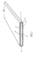
- Fig. 1 shows a preferred design of this when two textile ribbons that are coated on one side are used, and where the ribbons are folded around each other and where the overlap constitutes 50% of the circumference of the hose.
- the textile ribbons that are coated on one side are indicated by (1' and I") and the coating by (2).
- the butt and butt joints are indicated by (3' and 3") and the sets in the bending zone of the hose by (4).
- the textile is of a non-rotting material like polyamide and polyester, or a fungicide or germicide is added, for instance Sanitized@, if the material is of cotton, linen or other natural fibres.
- At least some of the threads of the textile must be oriented in the longitudinal direction of the hose. This is achieved by weaving the threads 90° in relation to each other, i.e. 50% of the threads are placed lengthwise and 50% are placed 90° crosswise in the longitudinal direction of the hose.
- the threads of the textile ribbon can either be twisted or not. Usually twisted threads are used.
- the thread weight will normally be between 20-150 deniers (2,22-16,66 tex).
- the textile ribbons can be coated on one or both sides.
- a coating for the said purpose will be on the basis of polyurethan, but polyvinylacetate, polyvinylchloride or another thermoplastic or thermosetting material can also be used for the purpose. The reason for this is that the coating must be diffusionproof and be adhesive when it is heated.
- Fig. 2 shows the production of ribbons of the same type as those described according to Fig. 1.
- the ribbons that are coated on one side (1' and 1") are passed together into a guide unit (6), where the textile layers are folded one on top of the other.
- the folded ribbons are flattened in a heated press section (7), whereby the ribbons are laminated (glued together).
- the feeding of the ribbons is done in a known manner by pulling the ribbons through the folding device.
- the ribbon that is to form the inner layer (1') is folded from the top in such a way that it is shaped like a reversed U, thus t1. See section B-B, Fig. 2.
- the outer ribbon (1") is folded around this from below, so that this also is shaped like an open U, thus U.
- the inner ribbon (1') is closed in a butt and butt joint (3'). See section C-C, Fig. 2.
- Fig. 2 shows a press device (7) where the folded ribbons (1' and 1 ") are squeezed between two parallel metal press ribbons. These can be heated in a known manner.
- Hoses that are produced according to the above description have, when being tried out, proved to be very well suited for the purpose. Another feature of such hoses is that they are easily mended when they have been perforated. The repairs are done most easily by ironing the hose with a hot iron, whereby the perforation is made impervious.
Landscapes
- Engineering & Computer Science (AREA)
- General Engineering & Computer Science (AREA)
- Mechanical Engineering (AREA)
- Textile Engineering (AREA)
- Rigid Pipes And Flexible Pipes (AREA)
- Materials For Medical Uses (AREA)
- Laminated Bodies (AREA)
Claims (2)
Priority Applications (1)
| Application Number | Priority Date | Filing Date | Title |
|---|---|---|---|
| AT82900667T ATE23397T1 (de) | 1982-02-18 | 1982-02-18 | Kontinuierlich hergestellter aufblasbarer schlauch und dessen herstellungsverfahren. |
Applications Claiming Priority (1)
| Application Number | Priority Date | Filing Date | Title |
|---|---|---|---|
| PCT/NO1982/000008 WO1983002989A1 (en) | 1982-02-18 | 1982-02-18 | Continuously produced inflatable hose including the mehtod of producing same |
Publications (2)
| Publication Number | Publication Date |
|---|---|
| EP0101435A1 EP0101435A1 (de) | 1984-02-29 |
| EP0101435B1 true EP0101435B1 (de) | 1986-11-05 |
Family
ID=19907187
Family Applications (1)
| Application Number | Title | Priority Date | Filing Date |
|---|---|---|---|
| EP82900667A Expired EP0101435B1 (de) | 1982-02-18 | 1982-02-18 | Kontinuierlich hergestellter aufblasbarer schlauch und dessen herstellungsverfahren |
Country Status (5)
| Country | Link |
|---|---|
| EP (1) | EP0101435B1 (de) |
| AT (1) | ATE23397T1 (de) |
| DE (1) | DE3274146D1 (de) |
| DK (1) | DK478183D0 (de) |
| WO (1) | WO1983002989A1 (de) |
Families Citing this family (2)
| Publication number | Priority date | Publication date | Assignee | Title |
|---|---|---|---|---|
| FR2614671B1 (fr) * | 1987-04-30 | 1990-11-30 | Caoutchouc Manuf Plastique | Tuyau flexible capable d'accepter de faibles rayons de courbure et procede pour sa fabrication |
| DE8811045U1 (de) * | 1988-09-01 | 1990-01-04 | Houben Kunststofftechnik GmbH, 4060 Viersen | Druckschlauch |
Family Cites Families (6)
| Publication number | Priority date | Publication date | Assignee | Title |
|---|---|---|---|---|
| US2580665A (en) * | 1952-01-01 | Method for forming paper can bodies | ||
| US651425A (en) * | 1899-07-05 | 1900-06-12 | John A Mcconnell | Pipe-covering. |
| US1469519A (en) * | 1920-06-28 | 1923-10-02 | John T Lister | Hose |
| US2424315A (en) * | 1944-03-09 | 1947-07-22 | Columbus Coated Fabrics Corp | Fabric tube |
| US2468493A (en) * | 1945-07-16 | 1949-04-26 | Arrowhead Rubber Company | Duct |
| BE754793A (fr) * | 1969-08-14 | 1971-02-15 | America Esna Corp | Ameliorations des (ou relatives aux) canalisations souples |
-
1982
- 1982-02-18 WO PCT/NO1982/000008 patent/WO1983002989A1/en not_active Ceased
- 1982-02-18 DE DE8282900667T patent/DE3274146D1/de not_active Expired
- 1982-02-18 EP EP82900667A patent/EP0101435B1/de not_active Expired
- 1982-02-18 AT AT82900667T patent/ATE23397T1/de not_active IP Right Cessation
-
1983
- 1983-10-17 DK DK4781/83A patent/DK478183D0/da not_active Application Discontinuation
Also Published As
| Publication number | Publication date |
|---|---|
| DK478183A (da) | 1983-10-17 |
| DK478183D0 (da) | 1983-10-17 |
| ATE23397T1 (de) | 1986-11-15 |
| WO1983002989A1 (en) | 1983-09-01 |
| DE3274146D1 (en) | 1986-12-11 |
| EP0101435A1 (de) | 1984-02-29 |
Similar Documents
| Publication | Publication Date | Title |
|---|---|---|
| RU2189316C2 (ru) | Удлиняемый листовой элемент (варианты), способ изготовления удлиняемого листового элемента (варианты) | |
| US6708729B1 (en) | Fiber reinforced composite liner for lining an existing conduit and method of manufacture | |
| US20050028881A1 (en) | Fiber reinforced composite liner for lining an existing conduit and method of manufacture | |
| US4308896A (en) | Fabric reinforced hose | |
| US20030113489A1 (en) | Fiber reinforced cured in place liner for lining an existing conduit and method of manufacture | |
| JPS5833098B2 (ja) | 管状裏打材の製造方法 | |
| JPH05505228A (ja) | 側壁に隣接した軸線方向の繊維を有する複合管状部材 | |
| KR19980071864A (ko) | 관 라이닝재 및 그 제조방법 | |
| US20210041043A1 (en) | Method of Lining Pipe with High Strength Liner, High Strength Liner, and Pipe Lined with High Strength Liner | |
| EP0101435B1 (de) | Kontinuierlich hergestellter aufblasbarer schlauch und dessen herstellungsverfahren | |
| AU544504B2 (en) | Continuously produced inflatable hose including the method ofproducing same | |
| CA1198380A (en) | Continuously produced inflatable hose including the method of producing same | |
| JP4545399B2 (ja) | 更生材およびその製造方法 | |
| US11173634B2 (en) | Electromagnetic radiation curable pipe liner and method of making and installing the same | |
| JP6975550B2 (ja) | 管路のライニング材 | |
| NZ201351A (en) | Inflatable hose and manufacture thereof | |
| RU2097196C1 (ru) | Способ изготовления санирующего рукава для трубопроводов | |
| US2011452A (en) | Manufacturing paper tubes and the like | |
| JP6878135B2 (ja) | 管路のライニング材およびその使用方法 | |
| US537318A (en) | Hose and method of making same | |
| JP2001219471A (ja) | 管ライニング材とその製造方法及び管ライニング工法 | |
| KR20060123468A (ko) | 제지용 직물의 이음부 형성 방법 및 장치, 그리고 이음된제지용 직물 | |
| JPS63249629A (ja) | 複合管状体 | |
| US31552A (en) | Thomas j | |
| JPS5919115A (ja) | 膨脹可能なホ−スおよび膨脹可能なホ−スを製造する方法 |
Legal Events
| Date | Code | Title | Description |
|---|---|---|---|
| PUAI | Public reference made under article 153(3) epc to a published international application that has entered the european phase |
Free format text: ORIGINAL CODE: 0009012 |
|
| 17P | Request for examination filed |
Effective date: 19831004 |
|
| AK | Designated contracting states |
Kind code of ref document: A1 Designated state(s): AT BE DE FR GB NL SE |
|
| RAP1 | Party data changed (applicant data changed or rights of an application transferred) |
Owner name: HEGER PLASTIC A/S |
|
| GRAA | (expected) grant |
Free format text: ORIGINAL CODE: 0009210 |
|
| AK | Designated contracting states |
Kind code of ref document: B1 Designated state(s): AT BE DE FR GB NL SE |
|
| PG25 | Lapsed in a contracting state [announced via postgrant information from national office to epo] |
Ref country code: NL Effective date: 19861105 |
|
| REF | Corresponds to: |
Ref document number: 23397 Country of ref document: AT Date of ref document: 19861115 Kind code of ref document: T |
|
| REF | Corresponds to: |
Ref document number: 3274146 Country of ref document: DE Date of ref document: 19861211 |
|
| ET | Fr: translation filed | ||
| BECN | Be: change of holder's name |
Effective date: 19861105 |
|
| RAP2 | Party data changed (patent owner data changed or rights of a patent transferred) |
Owner name: HEGER PLAST A/S |
|
| PG25 | Lapsed in a contracting state [announced via postgrant information from national office to epo] |
Ref country code: AT Effective date: 19870218 |
|
| PG25 | Lapsed in a contracting state [announced via postgrant information from national office to epo] |
Ref country code: SE Effective date: 19870219 |
|
| NLV1 | Nl: lapsed or annulled due to failure to fulfill the requirements of art. 29p and 29m of the patents act | ||
| PLBE | No opposition filed within time limit |
Free format text: ORIGINAL CODE: 0009261 |
|
| STAA | Information on the status of an ep patent application or granted ep patent |
Free format text: STATUS: NO OPPOSITION FILED WITHIN TIME LIMIT |
|
| BERE | Be: lapsed |
Owner name: HEGER PLAST A/S Effective date: 19870228 |
|
| 26N | No opposition filed | ||
| PG25 | Lapsed in a contracting state [announced via postgrant information from national office to epo] |
Ref country code: FR Free format text: LAPSE BECAUSE OF NON-PAYMENT OF DUE FEES Effective date: 19871030 |
|
| PG25 | Lapsed in a contracting state [announced via postgrant information from national office to epo] |
Ref country code: DE Effective date: 19871103 |
|
| REG | Reference to a national code |
Ref country code: FR Ref legal event code: ST |
|
| GBPC | Gb: european patent ceased through non-payment of renewal fee | ||
| PG25 | Lapsed in a contracting state [announced via postgrant information from national office to epo] |
Ref country code: GB Free format text: LAPSE BECAUSE OF NON-PAYMENT OF DUE FEES Effective date: 19881122 |
|
| PG25 | Lapsed in a contracting state [announced via postgrant information from national office to epo] |
Ref country code: BE Effective date: 19890228 |
|
| EUG | Se: european patent has lapsed |
Ref document number: 82900667.5 Effective date: 19880215 |