EP0101293A2 - Flexibles Auspuffventil mit Innenkühlung - Google Patents
Flexibles Auspuffventil mit Innenkühlung Download PDFInfo
- Publication number
- EP0101293A2 EP0101293A2 EP83304604A EP83304604A EP0101293A2 EP 0101293 A2 EP0101293 A2 EP 0101293A2 EP 83304604 A EP83304604 A EP 83304604A EP 83304604 A EP83304604 A EP 83304604A EP 0101293 A2 EP0101293 A2 EP 0101293A2
- Authority
- EP
- European Patent Office
- Prior art keywords
- exhaust valve
- valve
- exhaust
- round
- stem
- Prior art date
- Legal status (The legal status is an assumption and is not a legal conclusion. Google has not performed a legal analysis and makes no representation as to the accuracy of the status listed.)
- Withdrawn
Links
- 238000002485 combustion reaction Methods 0.000 claims 1
- 239000004215 Carbon black (E152) Substances 0.000 abstract description 5
- 229930195733 hydrocarbon Natural products 0.000 abstract description 5
- 150000002430 hydrocarbons Chemical class 0.000 abstract description 5
- 238000001816 cooling Methods 0.000 abstract description 4
- XLYOFNOQVPJJNP-UHFFFAOYSA-N water Substances O XLYOFNOQVPJJNP-UHFFFAOYSA-N 0.000 description 16
- 241000722921 Tulipa gesneriana Species 0.000 description 8
- 230000005494 condensation Effects 0.000 description 5
- 238000009833 condensation Methods 0.000 description 5
- 239000007789 gas Substances 0.000 description 5
- 238000009792 diffusion process Methods 0.000 description 4
- 238000001704 evaporation Methods 0.000 description 4
- 230000008020 evaporation Effects 0.000 description 4
- 230000009467 reduction Effects 0.000 description 4
- 238000007789 sealing Methods 0.000 description 4
- 238000003466 welding Methods 0.000 description 3
- VTYYLEPIZMXCLO-UHFFFAOYSA-L Calcium carbonate Chemical compound [Ca+2].[O-]C([O-])=O VTYYLEPIZMXCLO-UHFFFAOYSA-L 0.000 description 2
- CURLTUGMZLYLDI-UHFFFAOYSA-N Carbon dioxide Chemical compound O=C=O CURLTUGMZLYLDI-UHFFFAOYSA-N 0.000 description 2
- PXHVJJICTQNCMI-UHFFFAOYSA-N Nickel Chemical compound [Ni] PXHVJJICTQNCMI-UHFFFAOYSA-N 0.000 description 2
- BRPQOXSCLDDYGP-UHFFFAOYSA-N calcium oxide Chemical compound [O-2].[Ca+2] BRPQOXSCLDDYGP-UHFFFAOYSA-N 0.000 description 2
- 239000000292 calcium oxide Substances 0.000 description 2
- ODINCKMPIJJUCX-UHFFFAOYSA-N calcium oxide Inorganic materials [Ca]=O ODINCKMPIJJUCX-UHFFFAOYSA-N 0.000 description 2
- 229910002092 carbon dioxide Inorganic materials 0.000 description 2
- 239000002826 coolant Substances 0.000 description 2
- 230000006866 deterioration Effects 0.000 description 2
- 239000012530 fluid Substances 0.000 description 2
- 230000006698 induction Effects 0.000 description 2
- 239000000463 material Substances 0.000 description 2
- 238000010926 purge Methods 0.000 description 2
- 238000010791 quenching Methods 0.000 description 2
- 230000000171 quenching effect Effects 0.000 description 2
- 230000008646 thermal stress Effects 0.000 description 2
- 235000005749 Anthriscus sylvestris Nutrition 0.000 description 1
- 235000004412 Jasminum grandiflorum Nutrition 0.000 description 1
- 240000005067 Jasminum grandiflorum Species 0.000 description 1
- 229910045601 alloy Inorganic materials 0.000 description 1
- 239000000956 alloy Substances 0.000 description 1
- 230000004888 barrier function Effects 0.000 description 1
- 229910000019 calcium carbonate Inorganic materials 0.000 description 1
- 239000001569 carbon dioxide Substances 0.000 description 1
- 238000010438 heat treatment Methods 0.000 description 1
- 229910001026 inconel Inorganic materials 0.000 description 1
- 239000007788 liquid Substances 0.000 description 1
- 230000007774 longterm Effects 0.000 description 1
- 238000003754 machining Methods 0.000 description 1
- 239000000155 melt Substances 0.000 description 1
- 238000000034 method Methods 0.000 description 1
- 229910052759 nickel Inorganic materials 0.000 description 1
- 238000003908 quality control method Methods 0.000 description 1
- 230000003068 static effect Effects 0.000 description 1
- 230000035882 stress Effects 0.000 description 1
Images

Classifications
-
- F—MECHANICAL ENGINEERING; LIGHTING; HEATING; WEAPONS; BLASTING
- F01—MACHINES OR ENGINES IN GENERAL; ENGINE PLANTS IN GENERAL; STEAM ENGINES
- F01L—CYCLICALLY OPERATING VALVES FOR MACHINES OR ENGINES
- F01L3/00—Lift-valve, i.e. cut-off apparatus with closure members having at least a component of their opening and closing motion perpendicular to the closing faces; Parts or accessories thereof
- F01L3/12—Cooling of valves
- F01L3/14—Cooling of valves by means of a liquid or solid coolant, e.g. sodium, in a closed chamber in a valve
Definitions
- unburned HC comprises a significant automotive emission problem
- the exact origin of unburned. HC is, still today, a subject of controversy.
- the origin of unburned HC was primarily from a quenching boundary layer; but it has now been shown both theoretically and experimentally that the quenching boundary layer is depleted by diffusion during the expansion stroke to such a degree that it must account for less than 4 percent of unburned HC emissions. It has been known for a decade (since the work of Tabazinsky and Keck at MIT) that the concentration of unburned HC in the exhaust is not homogeneous.
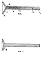
- Tulip Section 1 which is shaped so as to have significant ability to conform to the unround seat on which Sealing Surface 2 must seal.
- Tulip Section 1 is several orders of magnitude more flexible than the tulip section of conventional exhaust valves, which is typically a plug absolutely incapable of conforming to valve seat out-of-round. It should be clear to those skilled in the automotive arts that Tulip Section 1, partly because of its increased gas side surface area but mainly because of its reduced sections, comprises a cooling problem which will require an internally-cooled valve stem if expensive materials, such as inconel, are to be avoided.
- Tulip Section 1 is welded to Tubular Stem 4 at 3, preferably by means of a friction weld. It is much cheaper to friction weld a tubular stem to the tulip section rather than to forge the tulip and stem into one piece and then gun drill the stem, as is the current practice for internally-cooled valves.
- the internal chamber of Tubular Stem 4 will be sealed extremely well by Plug 6 if Plug 6 is first plated by an alloy such as pure nickel which lends itself to diffusion-welding. Plug 6 is tightly pressfit into Tubular Stem 4 and then passed through an induction coil for rapid induction heating and welding. In the internal chamber of the Tubular Stem 4 is Water 5 which serves as a coolant.
- the Water 5 inside Tubular Stem 4 be in a chambel sealed well enough to contain it for extended periods, and it is also important that the chamber in which the water is contained is devoid of non-condensible gases which reduces the efficiency of the evaporation/condensation heat transfer process.
- This can be achieved by putting the water in the chamber in the form of ice, accompanied by some calcium oxide and purging the chamber with carbon dioxide prior to welding. This done, Plug 6 is pressfit into Tube 4 and then rapidly induction-diffusion welded to form a seal. When the ice melts, the calcium oxide in the water will react with the C0 2 gas in the chamber to form calcium carbonate, leaving water and water vapor as the only fluids in the chamber.
- the water in the chamber 4 will form an extremely effective heat transfer arrangement capable of maintaining Tubular Stem 4 in a substantially isothermal condition. It is important that there be room in the chamber for water to expand as it is heated. Ideally, the contents of the chamber should be about half liquid and half gas when at a temperature just below the critical point of water. Under these conditions, the heat transfer through the valve stem via the evaporation/condensation cycle is quite efficient.
- the size of the hole in the valve stem need not be large (it may, for example, be as small as 1/8 of an inch) because the-viscosity of water becomes quite low at the temperatures at which the evaporation/condensation heat transfer must occur.
- the end of the valve stem has a Section 7 which may be integral with Plug 6 adapted to the valve keepers which is welded to Stem 4 by diffusion or friction.
- FIG. 2 shows a conventional exhaust valve for the purposes of comparison.
- Tulip Section 8 is so stiff as to preclude conformance of the valve to an out-of-round seat.
- Figure 3 shows a comparison of measured leakage in a steady state rig with a stock type exhaust valve on a set out-of-round by .002" compared to a flexible exhaust valve substantially as shown in Figure 1.
- Points on the lower curve are for the flexible valve; the higher leakages are for the stock exhaust valve. Leakage is far less with the flexible valve.
- Other data (not shown) has indicated that the flexible valve's ability to conform to seat out-of-round much in excess of .002" is limited.
- the combination of a flexible internally-cooled exhaust valve with good quality control on valve seat roundness should substantially reduce exhaust leakage, improve HC emissions and improve engine life.
Landscapes
- Engineering & Computer Science (AREA)
- Mechanical Engineering (AREA)
- General Engineering & Computer Science (AREA)
- Lift Valve (AREA)
- Valve Device For Special Equipments (AREA)
- Valve-Gear Or Valve Arrangements (AREA)
Applications Claiming Priority (2)
| Application Number | Priority Date | Filing Date | Title |
|---|---|---|---|
| US40749382A | 1982-08-12 | 1982-08-12 | |
| US407493 | 1982-08-12 |
Publications (2)
| Publication Number | Publication Date |
|---|---|
| EP0101293A2 true EP0101293A2 (de) | 1984-02-22 |
| EP0101293A3 EP0101293A3 (de) | 1985-01-16 |
Family
ID=23612319
Family Applications (1)
| Application Number | Title | Priority Date | Filing Date |
|---|---|---|---|
| EP83304604A Withdrawn EP0101293A3 (de) | 1982-08-12 | 1983-08-09 | Flexibles Auspuffventil mit Innenkühlung |
Country Status (3)
| Country | Link |
|---|---|
| EP (1) | EP0101293A3 (de) |
| JP (1) | JPS5954714A (de) |
| BR (1) | BR8304324A (de) |
Cited By (1)
| Publication number | Priority date | Publication date | Assignee | Title |
|---|---|---|---|---|
| US4790272A (en) * | 1987-10-15 | 1988-12-13 | Woolenweber William E | Non-circular poppet valves for internal combustion engine cylinder assemblies |
Family Cites Families (2)
| Publication number | Priority date | Publication date | Assignee | Title |
|---|---|---|---|---|
| DE1188864B (de) * | 1959-06-03 | 1965-03-11 | Maschf Augsburg Nuernberg Ag | Ventilsteuerung fuer Brennkraftmaschinen, insbesondere mit Tulpenventil |
| DE2727006A1 (de) * | 1977-06-15 | 1978-12-21 | Kloeckner Humboldt Deutz Ag | Tellerventil mit innenkuehlung, insbesondere auslassventil fuer hubkolbenbrennkraftmaschinen |
-
1983
- 1983-08-09 EP EP83304604A patent/EP0101293A3/de not_active Withdrawn
- 1983-08-11 BR BR8304324A patent/BR8304324A/pt unknown
- 1983-08-12 JP JP14792483A patent/JPS5954714A/ja active Pending
Cited By (1)
| Publication number | Priority date | Publication date | Assignee | Title |
|---|---|---|---|---|
| US4790272A (en) * | 1987-10-15 | 1988-12-13 | Woolenweber William E | Non-circular poppet valves for internal combustion engine cylinder assemblies |
Also Published As
| Publication number | Publication date |
|---|---|
| EP0101293A3 (de) | 1985-01-16 |
| BR8304324A (pt) | 1984-03-20 |
| JPS5954714A (ja) | 1984-03-29 |
Similar Documents
| Publication | Publication Date | Title |
|---|---|---|
| US7323043B2 (en) | Storage container associated with a thermal energy management system | |
| CN102331203B (zh) | 一种用于汽车刹车片的热管 | |
| US6019081A (en) | Cooled pre-combustion chamber assembly | |
| US3983696A (en) | Combustion engine having at least one outlet passage | |
| GB2504517A (en) | A sleeve with integrated heat pipes for seating engine components in a cylinder head | |
| KR840005790A (ko) | 고온 유체 공급 튜브 장치 및 진공유지 방법 | |
| US3822680A (en) | Isothermal valve seat for internal combustion engine | |
| EP0101293A2 (de) | Flexibles Auspuffventil mit Innenkühlung | |
| CN110388510B (zh) | 具有冷却功能的高温阀的控制系统及控制方法 | |
| JP3757166B2 (ja) | 熱交換器及びこれを形成する方法 | |
| JPS6336403B2 (de) | ||
| WO2001033066A1 (en) | Exhaust port structure of internal combustion engine | |
| US2009045A (en) | Method of making valves | |
| US2362622A (en) | Injection engine | |
| EP1091104B1 (de) | Zusammenbau einer gekühlten Vorkammer | |
| JPH0223767Y2 (de) | ||
| US4478042A (en) | Cylinder liner-regenerator unit for a hot gas engine | |
| RU32526U1 (ru) | Теплоизолированная колонна | |
| US2086420A (en) | Engine valve | |
| JP2971685B2 (ja) | 熱交換器およびその製造方法 | |
| Smith Jr | A Metal Bellows Expansion Engine | |
| Jones | Fatigue behavior of exhaust valve alloys | |
| EP0049941A1 (de) | Mittel zum Vermeiden von Wärmeströmung zur Komponentoberfläche der thermodynamischen Kolbenmaschinen | |
| JPS629184A (ja) | 熱交換器 | |
| US4708165A (en) | High pressure stepped clearance seal valve in a cryogenic refrigeration system |
Legal Events
| Date | Code | Title | Description |
|---|---|---|---|
| PUAI | Public reference made under article 153(3) epc to a published international application that has entered the european phase |
Free format text: ORIGINAL CODE: 0009012 |
|
| AK | Designated contracting states |
Designated state(s): DE FR GB IT SE |
|
| PUAL | Search report despatched |
Free format text: ORIGINAL CODE: 0009013 |
|
| AK | Designated contracting states |
Designated state(s): DE FR GB IT SE |
|
| 17P | Request for examination filed |
Effective date: 19850709 |
|
| STAA | Information on the status of an ep patent application or granted ep patent |
Free format text: STATUS: THE APPLICATION IS DEEMED TO BE WITHDRAWN |
|
| 18D | Application deemed to be withdrawn |
Effective date: 19860318 |
|
| RIN1 | Information on inventor provided before grant (corrected) |
Inventor name: SHOWALTER, MERLE ROBERT |