EP0101293A2 - Internally cooled flexible exhaust valve - Google Patents
Internally cooled flexible exhaust valve Download PDFInfo
- Publication number
- EP0101293A2 EP0101293A2 EP83304604A EP83304604A EP0101293A2 EP 0101293 A2 EP0101293 A2 EP 0101293A2 EP 83304604 A EP83304604 A EP 83304604A EP 83304604 A EP83304604 A EP 83304604A EP 0101293 A2 EP0101293 A2 EP 0101293A2
- Authority
- EP
- European Patent Office
- Prior art keywords
- exhaust valve
- valve
- exhaust
- round
- stem
- Prior art date
- Legal status (The legal status is an assumption and is not a legal conclusion. Google has not performed a legal analysis and makes no representation as to the accuracy of the status listed.)
- Withdrawn
Links
Images

Classifications
-
- F—MECHANICAL ENGINEERING; LIGHTING; HEATING; WEAPONS; BLASTING
- F01—MACHINES OR ENGINES IN GENERAL; ENGINE PLANTS IN GENERAL; STEAM ENGINES
- F01L—CYCLICALLY OPERATING VALVES FOR MACHINES OR ENGINES
- F01L3/00—Lift-valve, i.e. cut-off apparatus with closure members having at least a component of their opening and closing motion perpendicular to the closing faces; Parts or accessories thereof
- F01L3/12—Cooling of valves
- F01L3/14—Cooling of valves by means of a liquid or solid coolant, e.g. sodium, in a closed chamber in a valve
Definitions
- unburned HC comprises a significant automotive emission problem
- the exact origin of unburned. HC is, still today, a subject of controversy.
- the origin of unburned HC was primarily from a quenching boundary layer; but it has now been shown both theoretically and experimentally that the quenching boundary layer is depleted by diffusion during the expansion stroke to such a degree that it must account for less than 4 percent of unburned HC emissions. It has been known for a decade (since the work of Tabazinsky and Keck at MIT) that the concentration of unburned HC in the exhaust is not homogeneous.
- Tulip Section 1 which is shaped so as to have significant ability to conform to the unround seat on which Sealing Surface 2 must seal.
- Tulip Section 1 is several orders of magnitude more flexible than the tulip section of conventional exhaust valves, which is typically a plug absolutely incapable of conforming to valve seat out-of-round. It should be clear to those skilled in the automotive arts that Tulip Section 1, partly because of its increased gas side surface area but mainly because of its reduced sections, comprises a cooling problem which will require an internally-cooled valve stem if expensive materials, such as inconel, are to be avoided.
- Tulip Section 1 is welded to Tubular Stem 4 at 3, preferably by means of a friction weld. It is much cheaper to friction weld a tubular stem to the tulip section rather than to forge the tulip and stem into one piece and then gun drill the stem, as is the current practice for internally-cooled valves.
- the internal chamber of Tubular Stem 4 will be sealed extremely well by Plug 6 if Plug 6 is first plated by an alloy such as pure nickel which lends itself to diffusion-welding. Plug 6 is tightly pressfit into Tubular Stem 4 and then passed through an induction coil for rapid induction heating and welding. In the internal chamber of the Tubular Stem 4 is Water 5 which serves as a coolant.
- the Water 5 inside Tubular Stem 4 be in a chambel sealed well enough to contain it for extended periods, and it is also important that the chamber in which the water is contained is devoid of non-condensible gases which reduces the efficiency of the evaporation/condensation heat transfer process.
- This can be achieved by putting the water in the chamber in the form of ice, accompanied by some calcium oxide and purging the chamber with carbon dioxide prior to welding. This done, Plug 6 is pressfit into Tube 4 and then rapidly induction-diffusion welded to form a seal. When the ice melts, the calcium oxide in the water will react with the C0 2 gas in the chamber to form calcium carbonate, leaving water and water vapor as the only fluids in the chamber.
- the water in the chamber 4 will form an extremely effective heat transfer arrangement capable of maintaining Tubular Stem 4 in a substantially isothermal condition. It is important that there be room in the chamber for water to expand as it is heated. Ideally, the contents of the chamber should be about half liquid and half gas when at a temperature just below the critical point of water. Under these conditions, the heat transfer through the valve stem via the evaporation/condensation cycle is quite efficient.
- the size of the hole in the valve stem need not be large (it may, for example, be as small as 1/8 of an inch) because the-viscosity of water becomes quite low at the temperatures at which the evaporation/condensation heat transfer must occur.
- the end of the valve stem has a Section 7 which may be integral with Plug 6 adapted to the valve keepers which is welded to Stem 4 by diffusion or friction.
- FIG. 2 shows a conventional exhaust valve for the purposes of comparison.
- Tulip Section 8 is so stiff as to preclude conformance of the valve to an out-of-round seat.
- Figure 3 shows a comparison of measured leakage in a steady state rig with a stock type exhaust valve on a set out-of-round by .002" compared to a flexible exhaust valve substantially as shown in Figure 1.
- Points on the lower curve are for the flexible valve; the higher leakages are for the stock exhaust valve. Leakage is far less with the flexible valve.
- Other data (not shown) has indicated that the flexible valve's ability to conform to seat out-of-round much in excess of .002" is limited.
- the combination of a flexible internally-cooled exhaust valve with good quality control on valve seat roundness should substantially reduce exhaust leakage, improve HC emissions and improve engine life.
Abstract
A flexible exhaust valve capable of conforming to a valve seat slightly out-of-round is disclosed. This valve, which includes internal cooling, will produce an excellent exhaust seal when used in combination with an exhaust valve seat that is machined round within about .001 inches. The improved seal is expected to reduce emissions of unburned hydrocarbon and improve engine life.
Description
- Although unburned HC comprises a significant automotive emission problem, the exact origin of unburned. HC is, still today, a subject of controversy. Until recently, it was believed that the origin of unburned HC was primarily from a quenching boundary layer; but it has now been shown both theoretically and experimentally that the quenching boundary layer is depleted by diffusion during the expansion stroke to such a degree that it must account for less than 4 percent of unburned HC emissions. It has been known for a decade (since the work of Tabazinsky and Keck at MIT) that the concentration of unburned HC in the exhaust is not homogeneous. There is a large concentration of unburned HC at the beginning of the exhaust stroke, a relatively very low (perhaps in reality zero) concentration of HC during the middle part of the exhaust stroke, and a significant concentration of unburned HC emissions towards the end. It is the belief of the inventor that the first mass of unburned HC really comprises unburned hydrocarbon due to leakage of the exhaust valve seal. It is fairly well established that the last mass of hydrocarbon is due to roll-up vortex fluid mechanics in the cylinder. It is the purpose of the present invention to produce an exhaust seal which does not leak.
- Current exhaust valves do leak in service. The exhaust valves themselves have evolved into very stiff objects incapable of conformal sealing due to considerations of fatigue control, and the exhaust valve seats themselves are frequently considerably out-of-round. Automotive Engine Associates has conducted at Southwest Research Institute a roundness test of a large number of exhaust valve seats on more than 100 2.3 L Ford engines, and has also measured a fair number of exhaust valve seats on other engines. The exhaust valve seats measured were, with few exceptions, sufficiently out-of-round to produce significant leakage of the exhaust valve seal. Tests using a static leakage measure were conducted with conventional exhaust valves and seats. Leakage rates sufficiently high to account for all or a large fraction of the unburned hydrocarbon from the engine were found. The Automotive Engine Associates team then tested valve shapes which would tend to conform to valve seat out-of-round. Significant reductions in leakage past the exhaust seals were found; however, it was discovered that, even with the most flexible, structurally sound valve shape, the excellent sealing of the exhaust valve was not compatible with standard exhaust seat roundness. Moreover, it was established that the majority of exhaust valve seat out-of-round is due to machining and hardening errors, and not to thermal stresses or stresses set up in the assembly of the engine. A substantially better seal was obtained by combining exhaust valve seats which were .001" out-of-round (but preferably .0005" or less out-of-round) with a flexible exhaust valve. This valve can be long-lived and made of conventional exhaust valve materials if carefully internally-cooled. It is believed that the combination of a flexible, carefully cooled exhaust valve and an exhaust seat machined to be nearly round can produce a more than order of magnitude reduction in exhaust leakage, and consequently a significant reduction in unburned hydrocarbon from engines. In addition, reduction in exhaust leakage is expected to reduce deterioration of the exhaust seals, thereby lenthening the life of the engine and preventing long-term deterioration of emissions control.
-
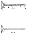
- Figure 1 is a cross sectional view of the internally cooled flexible exhaust valve of the present invention.
- Figure 2 shows a cross section of a typical exhaust valve for comparison.
- Figure 3 shows the results of leakage tests with the flexible valve on a seat with out-of-round less than .002" compared to a stock exhaust valve on this same seat.
- See Figure 1. Valve Seat Surface 2 is supported by nearly conical shaped Tulip Section 1 which is shaped so as to have significant ability to conform to the unround seat on which Sealing
Surface 2 must seal. Tulip Section 1 is several orders of magnitude more flexible than the tulip section of conventional exhaust valves, which is typically a plug absolutely incapable of conforming to valve seat out-of-round. It should be clear to those skilled in the automotive arts that Tulip Section 1, partly because of its increased gas side surface area but mainly because of its reduced sections, comprises a cooling problem which will require an internally-cooled valve stem if expensive materials, such as inconel, are to be avoided. - Tulip Section 1 is welded to
Tubular Stem 4 at 3, preferably by means of a friction weld. It is much cheaper to friction weld a tubular stem to the tulip section rather than to forge the tulip and stem into one piece and then gun drill the stem, as is the current practice for internally-cooled valves. The internal chamber of TubularStem 4 will be sealed extremely well byPlug 6 ifPlug 6 is first plated by an alloy such as pure nickel which lends itself to diffusion-welding.Plug 6 is tightly pressfit intoTubular Stem 4 and then passed through an induction coil for rapid induction heating and welding. In the internal chamber of the TubularStem 4 isWater 5 which serves as a coolant. The use of water as an internal valve stem coolant has been tested for a number of years. Fairly extensive tests were run at Eaton Corporation (see SAE 730055), the results of which were spotty, and it is now believed that the reasons for the previous unreliability of water cooling were: 1.) The possibility of pinhole leaks through which the water could escape, destroying the cooling. 2.) The fact that no effort was made to purge out non-condensible gases from the stem so as to eliminate condensation diffusion barriers which reduce heat transfer of evaporation and condensation by an order of magnitude. It is important that the Water 5 insideTubular Stem 4 be in a chambel sealed well enough to contain it for extended periods, and it is also important that the chamber in which the water is contained is devoid of non-condensible gases which reduces the efficiency of the evaporation/condensation heat transfer process. This can be achieved by putting the water in the chamber in the form of ice, accompanied by some calcium oxide and purging the chamber with carbon dioxide prior to welding. This done,Plug 6 is pressfit intoTube 4 and then rapidly induction-diffusion welded to form a seal. When the ice melts, the calcium oxide in the water will react with the C02 gas in the chamber to form calcium carbonate, leaving water and water vapor as the only fluids in the chamber. Once this is done, the water in thechamber 4 will form an extremely effective heat transfer arrangement capable of maintainingTubular Stem 4 in a substantially isothermal condition. It is important that there be room in the chamber for water to expand as it is heated. Ideally, the contents of the chamber should be about half liquid and half gas when at a temperature just below the critical point of water. Under these conditions, the heat transfer through the valve stem via the evaporation/condensation cycle is quite efficient. The size of the hole in the valve stem need not be large (it may, for example, be as small as 1/8 of an inch) because the-viscosity of water becomes quite low at the temperatures at which the evaporation/condensation heat transfer must occur. - The end of the valve stem has a
Section 7 which may be integral withPlug 6 adapted to the valve keepers which is welded toStem 4 by diffusion or friction. - Figure 2 shows a conventional exhaust valve for the purposes of comparison. Those who are mechanically skilled will recognize that the shape of
Tulip Section 8 is so stiff as to preclude conformance of the valve to an out-of-round seat. - Figure 3 shows a comparison of measured leakage in a steady state rig with a stock type exhaust valve on a set out-of-round by .002" compared to a flexible exhaust valve substantially as shown in Figure 1. Points on the lower curve are for the flexible valve; the higher leakages are for the stock exhaust valve. Leakage is far less with the flexible valve. Other data (not shown) has indicated that the flexible valve's ability to conform to seat out-of-round much in excess of .002" is limited. For seats that are within .001", near perfect sealing results. Calculation indicates that if seats are manufactured within .001" of round, the total expected out-of-round due to mechanical and thermal stresses will be less than ..001" out-of-round. The combination of a flexible internally-cooled exhaust valve with good quality control on valve seat roundness should substantially reduce exhaust leakage, improve HC emissions and improve engine life.
Claims (1)
1. In an internal . combustion engine, the combination of an exhaust valve seat with .002" of roundness, an exhaust valve flexibly designed to accommodate out-of-round as described, and means to internally cool the valve stem of said exhaust valve.
Applications Claiming Priority (2)
| Application Number | Priority Date | Filing Date | Title |
|---|---|---|---|
| US40749382A | 1982-08-12 | 1982-08-12 | |
| US407493 | 1982-08-12 |
Publications (2)
| Publication Number | Publication Date |
|---|---|
| EP0101293A2 true EP0101293A2 (en) | 1984-02-22 |
| EP0101293A3 EP0101293A3 (en) | 1985-01-16 |
Family
ID=23612319
Family Applications (1)
| Application Number | Title | Priority Date | Filing Date |
|---|---|---|---|
| EP83304604A Withdrawn EP0101293A3 (en) | 1982-08-12 | 1983-08-09 | Internally cooled flexible exhaust valve |
Country Status (3)
| Country | Link |
|---|---|
| EP (1) | EP0101293A3 (en) |
| JP (1) | JPS5954714A (en) |
| BR (1) | BR8304324A (en) |
Cited By (1)
| Publication number | Priority date | Publication date | Assignee | Title |
|---|---|---|---|---|
| US4790272A (en) * | 1987-10-15 | 1988-12-13 | Woolenweber William E | Non-circular poppet valves for internal combustion engine cylinder assemblies |
Citations (2)
| Publication number | Priority date | Publication date | Assignee | Title |
|---|---|---|---|---|
| DE1188864B (en) * | 1959-06-03 | 1965-03-11 | Maschf Augsburg Nuernberg Ag | Valve control for internal combustion engines, especially with a tulip valve |
| DE2727006A1 (en) * | 1977-06-15 | 1978-12-21 | Kloeckner Humboldt Deutz Ag | IC piston engine exhaust valve - has interconnected cooling chambers in welded shaft, and disc with radial bores to periphery |
-
1983
- 1983-08-09 EP EP83304604A patent/EP0101293A3/en not_active Withdrawn
- 1983-08-11 BR BR8304324A patent/BR8304324A/en unknown
- 1983-08-12 JP JP14792483A patent/JPS5954714A/en active Pending
Patent Citations (2)
| Publication number | Priority date | Publication date | Assignee | Title |
|---|---|---|---|---|
| DE1188864B (en) * | 1959-06-03 | 1965-03-11 | Maschf Augsburg Nuernberg Ag | Valve control for internal combustion engines, especially with a tulip valve |
| DE2727006A1 (en) * | 1977-06-15 | 1978-12-21 | Kloeckner Humboldt Deutz Ag | IC piston engine exhaust valve - has interconnected cooling chambers in welded shaft, and disc with radial bores to periphery |
Non-Patent Citations (1)
| Title |
|---|
| MACHINE DESIGN, vol. 37, no. 4, 18th February 1965, page 190, Cleveland, USA; * |
Cited By (1)
| Publication number | Priority date | Publication date | Assignee | Title |
|---|---|---|---|---|
| US4790272A (en) * | 1987-10-15 | 1988-12-13 | Woolenweber William E | Non-circular poppet valves for internal combustion engine cylinder assemblies |
Also Published As
| Publication number | Publication date |
|---|---|
| JPS5954714A (en) | 1984-03-29 |
| BR8304324A (en) | 1984-03-20 |
| EP0101293A3 (en) | 1985-01-16 |
Similar Documents
| Publication | Publication Date | Title |
|---|---|---|
| US7323043B2 (en) | Storage container associated with a thermal energy management system | |
| US3911875A (en) | Cooled exhaust valve for an internal combustion engine | |
| CN102331203B (en) | Heat pipe applied to brake pad and production method thereof | |
| GB2504517A (en) | A sleeve with integrated heat pipes for seating engine components in a cylinder head | |
| JP2006518021A (en) | Cold-agent through cold end pressure vessel | |
| US3822680A (en) | Isothermal valve seat for internal combustion engine | |
| US4372377A (en) | Heat pipes containing alkali metal working fluid | |
| EP0101293A2 (en) | Internally cooled flexible exhaust valve | |
| JP3757166B2 (en) | Heat exchanger and method of forming the same | |
| JPS6336403B2 (en) | ||
| WO2001033066A1 (en) | Exhaust port structure of internal combustion engine | |
| US2362622A (en) | Injection engine | |
| EP1091104B1 (en) | Cooled pre-combustion chamber assembly | |
| JPH0223767Y2 (en) | ||
| JP2006300415A (en) | Heat exchanger device | |
| JPS628678B2 (en) | ||
| US2124362A (en) | Air insulated valve and guide for internal combustion engines | |
| JPH06174334A (en) | Heat exchanger and manufacture thereof | |
| Smith Jr | A Metal Bellows Expansion Engine | |
| JPS629184A (en) | Heat exchanger | |
| Jones | Fatigue behavior of exhaust valve alloys | |
| EP0049941A1 (en) | Means of preventing heat of working fluid from flowing into component surfaces of thermodynamic piston engines | |
| US848886A (en) | Cooling device for combustion-engines. | |
| JPS60175754A (en) | Heat accumulator unit | |
| JONES | Aluminum/ammonia heat pipe gas generation and long term system impact for the Space Telescope's Wide Field Planetary Camera |
Legal Events
| Date | Code | Title | Description |
|---|---|---|---|
| PUAI | Public reference made under article 153(3) epc to a published international application that has entered the european phase |
Free format text: ORIGINAL CODE: 0009012 |
|
| AK | Designated contracting states |
Designated state(s): DE FR GB IT SE |
|
| PUAL | Search report despatched |
Free format text: ORIGINAL CODE: 0009013 |
|
| AK | Designated contracting states |
Designated state(s): DE FR GB IT SE |
|
| 17P | Request for examination filed |
Effective date: 19850709 |
|
| STAA | Information on the status of an ep patent application or granted ep patent |
Free format text: STATUS: THE APPLICATION IS DEEMED TO BE WITHDRAWN |
|
| 18D | Application deemed to be withdrawn |
Effective date: 19860318 |
|
| RIN1 | Information on inventor provided before grant (corrected) |
Inventor name: SHOWALTER, MERLE ROBERT |