EP0100562B1 - Vorrichtung zur Herstellung von Röntgenbildern von Körpern - Google Patents
Vorrichtung zur Herstellung von Röntgenbildern von Körpern Download PDFInfo
- Publication number
- EP0100562B1 EP0100562B1 EP83107916A EP83107916A EP0100562B1 EP 0100562 B1 EP0100562 B1 EP 0100562B1 EP 83107916 A EP83107916 A EP 83107916A EP 83107916 A EP83107916 A EP 83107916A EP 0100562 B1 EP0100562 B1 EP 0100562B1
- Authority
- EP
- European Patent Office
- Prior art keywords
- ray
- detectors
- detector
- measuring points
- line
- Prior art date
- Legal status (The legal status is an assumption and is not a legal conclusion. Google has not performed a legal analysis and makes no representation as to the accuracy of the status listed.)
- Expired
Links
- 230000005855 radiation Effects 0.000 claims description 4
- 229910000679 solder Inorganic materials 0.000 description 3
- 238000005070 sampling Methods 0.000 description 2
- 238000007689 inspection Methods 0.000 description 1
- 230000000149 penetrating effect Effects 0.000 description 1
- 239000007787 solid Substances 0.000 description 1
Images

Classifications
-
- G—PHYSICS
- G01—MEASURING; TESTING
- G01N—INVESTIGATING OR ANALYSING MATERIALS BY DETERMINING THEIR CHEMICAL OR PHYSICAL PROPERTIES
- G01N23/00—Investigating or analysing materials by the use of wave or particle radiation, e.g. X-rays or neutrons, not covered by groups G01N3/00 – G01N17/00, G01N21/00 or G01N22/00
- G01N23/02—Investigating or analysing materials by the use of wave or particle radiation, e.g. X-rays or neutrons, not covered by groups G01N3/00 – G01N17/00, G01N21/00 or G01N22/00 by transmitting the radiation through the material
- G01N23/04—Investigating or analysing materials by the use of wave or particle radiation, e.g. X-rays or neutrons, not covered by groups G01N3/00 – G01N17/00, G01N21/00 or G01N22/00 by transmitting the radiation through the material and forming images of the material
- G01N23/043—Investigating or analysing materials by the use of wave or particle radiation, e.g. X-rays or neutrons, not covered by groups G01N3/00 – G01N17/00, G01N21/00 or G01N22/00 by transmitting the radiation through the material and forming images of the material using fluoroscopic examination, with visual observation or video transmission of fluoroscopic images
Definitions
- the invention relates to a device for generating X-ray images of bodies according to the preamble of patent claim 1.
- FR-A-2 352 296 A device with essential features of this type is described in FR-A-2 352 296. This device is used for medical examinations, the x-ray generator rotating with the detector line around the body. It is also known to arrange the detector line on a wall of a rectangular test room. However, this results in non-linear distortions in the distances, which increase with the distance from the perpendicular to the detector line.
- the object on which the present invention is based is to compensate for the nonlinear distortions in a device according to the preamble of patent claim 1, components and devices which are as common as possible are to be used.
- the invention is based on the knowledge that the change in the angle of the incident x-ray beam to the perpendicular from the x-ray generator to the straight line passing through the two adjacent measuring points is decisive for the degree of non-linear distortion.
- This relationship applies both to straight detector lines and to any curved detector lines which deviate from the shape of an arc, the center of which lies in the X-ray organizer. Even discontinuities in the profile of the detector lines do not disturb this relationship.
- Changing the distances between the measuring points also has the advantage that all other components and devices, in particular the monitor, can be commercially available components.
- the knowledge that the distance between two adjacent measuring points is proportional to the reciprocal of the cosine of the angle of the incident X-ray beam to the perpendicular from the X-ray generator to the straight line running through the two neighboring measuring points enables the distances between adjacent measuring points to be determined independently of the course of the detector line.
- the profile of the detector line can also contain discontinuities.
- a i means the distance between the measuring points with the numbers i and i + 1.
- the distance A o can be determined on the monitor after a predetermined number of pixels per line and according to the dimensions of the device.
- r j 1, it specifies the distance between two measuring points when the solder from the X-ray generator runs on the connecting line between the two measuring points through one of these two measuring points.
- Detector lines are advantageously guided along all walls that can be reached by the X-rays after passing through the test room.
- the device advantageously contains detector lines which contain detectors at a uniform spacing, not all detectors being used as measuring points for generating image points and the mutual spacing being determined by a corresponding selection of the detectors used.
- This embodiment has the advantage that series-made detector lines with constant distances from detectors can be used. Several pre-made detector lines can be arranged one behind the other and used to display only one line during playback on the monitor.
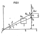
- X-rays 3 and 7 emanate from an X-ray generator 1.
- the x-ray generator 1 is to be regarded as a point-shaped x-ray radiation source. After penetrating the body 2, an x-ray beam 7 reaches the x-ray detector D i at a distance r i .
- This Röhtgenstrahl 7 forms the angle 8i with the solder from the X-ray generator 1 on the connecting line 8 between the X-ray detectors D i and D i + 1 .
- the differential area d m of the body 2 is imaged on the surface element d ' m without disturbing nonlinear distortion.
- the deviation of the angle of the beam 3 to the surface element d ' m from a right angle does not result in a non-linear distortion if the angle 8 between adjacent X-rays 3 and 7 is constant.
- the surface element d ' m forms the angle ⁇ i with the detector line 9.
- the distance A between the detector D i and the detector D i + 1 is proportional to the reciprocal of the cosine ⁇ ii A i is also proportional to the distance r j of the detector D i from the X-ray generator 1. This gives the formula
- the angle between the X-rays 3 and 7 is automatically taken into account.
- the position of the measuring points on arbitrarily shaped detector lines is determined in a simple manner by drawing a circle with the radius 1 around the X-ray generator, by starting from a beam from the X-ray generator to a first measuring point by applying the proportionality factor A o to the direction of the beam next measuring point and
- the corresponding angular range of the unit circle can also be divided by the number of pixel spacings provided. The rays through the resulting points on the unit circle immediately show the position of the measuring points on the detector lines.
- FIGS. 2 and 3 show a prefabricated detector line 4 with X-ray detectors D1, D2, which are arranged at uniform mutual distances in the detector line.
- the hatched detectors D1 are used as measuring points.
- Detectors D2, which are not hatched, are not used as measuring points.
- an inventive linearization of the image on the monitor is approximately achieved.
- Prefabricated and therefore inexpensive detector lines can be used, the selection of the detectors D2 used as measuring points can be matched to the respective device without the detector line 4 having to be changed.
- FIG. 3 shows the use of a detector line 4, which is composed of smaller sections 13, 14 and thereby contains a point of discontinuity.
- the section 14 is offset towards the X-ray generator 1, so that a smaller number of detectors D2 not required is necessary than in the example of FIG. 2, in which the parts of the detector line 4 which are relatively distant from the X-ray generator 1 already have a relatively large number of detectors not used D2 included.
- This example is particularly advantageous for the inspection of objects which have a smaller extent in their upper part than in their lower part.
- the equation A A o . applies to the two sections 13, 14 of the detector line 4.
- the plumb line 11, 12 which is based on the straight lines defined by the parts 13 and 14 must be used to determine the distances A. will.
- the solders 11, 12 coincide in their direction in the example shown and advantageously lie in the lower limit of the test space.
- an image can always be achieved on a commercially available monitor with the same line spacing without the disruptive nonlinear distortions.
- the distances can be adapted to different embodiments of the device, for example to different distances of the detector line from the X-ray generator.
- a simple configuration of the control is achieved in that the sampling frequency is modulated so that the total time for a single complete sampling of all detector lines remains unchanged.
- detector lines 4 instead of the detector lines 4 with the same distances between the individual detectors D1, D2, detector lines without detectors D2 not used can also be used if the detectors D1 used are arranged in different mutual distances corresponding to the above-mentioned equation for A.
Landscapes
- Health & Medical Sciences (AREA)
- Analytical Chemistry (AREA)
- General Physics & Mathematics (AREA)
- Nuclear Medicine, Radiotherapy & Molecular Imaging (AREA)
- Radiology & Medical Imaging (AREA)
- Physics & Mathematics (AREA)
- Life Sciences & Earth Sciences (AREA)
- Chemical & Material Sciences (AREA)
- Engineering & Computer Science (AREA)
- Multimedia (AREA)
- Biochemistry (AREA)
- General Health & Medical Sciences (AREA)
- Immunology (AREA)
- Pathology (AREA)
- Analysing Materials By The Use Of Radiation (AREA)
- Apparatus For Radiation Diagnosis (AREA)
- Measurement Of Radiation (AREA)
- X-Ray Techniques (AREA)
- Radiation-Therapy Devices (AREA)
Description
- Die Erfindung betrifft eine Vorrichtung zur Erzeugung von Röntgenbildern von Körpern gemäß dem Oberbegriff des Patentanspruches 1.
- Eine Vorrichtung mit wesentlichen Merkmalen dieser Art ist in der FR-A-2 352 296 beschrieben. Diese Vorrichtung dient für medizinische Untersuchungen, wobei sich der Röntgengenerator mit der Detektorzeile um den Körper dreht. Es ist ferner bekannt die Detektorzeile an einer Wand eines rechteckförmigen Prüfraumes anzuordnen. Dabei ergeben sich aber nichtlineare Verzerrungen der Abstände, die mit dem Abstand vom Lot auf die Detektorzeile größer werden.
- Die Aufgabe, die der vorliegenden Erfindung zugrundeliegt, besteht in einer Kompensation der nichtlinearen Verzerrungen bei einer Vorrichtung gemäß dem Oberbegriff des Patentanspruchs 1, wobei möglichst weitgehend übliche Bauteile bzw. Geräte eingesetzt werden sollen.
- Diese Aufgabe wird durch die kennzeichnenden Merkmale des Anspruches 1 gelöst.
- Der Erfindung liegt die Erkenntnis zugrunde, daß die Änderung des Winkels des auftreffenden Röntgenstrahls zum Lot vom Röntgenstrahlgenerator auf die durch die beiden benachbarten Meßpunkte verlaufende Gerade für das Maß der nichtlinearen Verzerrung ausschlaggebend ist. Diese Beziehung gilt sowohl für gerade Detektorzeilen als auch für beliebige gekrümmte Detektorzeilen, welche von der form eines Kreisbogens, dessen Mittelpunkt im Röntgenganerator liegt, abweichen. Auch Unstetigkeitsstellen im Profil der Detektorzeilen stören diese Beziehung nicht.
- Die Änderung der Abstände der Meßpunkte hat außerdem den Vorteil, daß alle übrigen Bauteile und Geräte, insbesondere auch der Monitor, handelsübliche Bauteile sein können.
- Die Erkenntnis, daß der Abstand zweier benachbarter Meßpunkte dem Kehrwert des Kosinus des Winkels des auftreffenden Röntgenstrahles zum Lot vom Röntgengenerator auf die durch die beiden benachbarten Meßpunkte verlaufende Gerade proportional ist, ermöglicht die Bestimmung der Abstände benachbarter Meßpunkte unabhängig vom Verlauf der Detektorzeile. Das Profil der Detektorzeile kann auch Unstetigkeitsstellen beinhalten.
- Die Bemessungsregel des Patentbegehrens kann auch formelhaft geschrieben werden:
- Ai = AO

- Hierbei bedeutet Ai den Abstand zwischen den Meßpunkten mit den Nummern i und i + 1. Der Abstand Ao kann nach dem einer vorgegebenen Anzahl von Bildpunkten je Zeile auf dem Monitor nach den Abmessungen des Gerätes bestimmt werden. Er gibt bei rj = 1 den Abstand zweier Meßpunkte an, wenn das Lot vom Röntgengenerator auf die Verbinddungslinie zwischen den beiden Meßpunkten durch einen von diesen beiden Meßpunkten läuft.
- Vorteilhaft sind Detektorzeilen an allen von der Röntgenstrahlung nach Durchlaufen des Prüfraums erreichbaren Wänden entlanggeführt.
- Vorteilhaft enthält die Vorrichtung Detektorzeilen, welche in gleichmäßigem Abstand Detektoren enthalten, wobei nicht alle Detektoren als Meßpunkte zur Erzeugung von Bildpunkten eingesetzt werden und wobei der gegenseitige Abstand durch eine entsprechende Auswahl der eingesetzten Detektoren festgelegt wird. Diese Ausführungsform hat den Vorteil, daß seriemäßig vorgefertigte Detektorzeilen mit konstanten Abständen von Detektoren eingesetzt werden können. Dabei können mehrere vorgefertigte Detektorzeilen hintereinander angeordnet und zur Darstellung nur einer Zeile bei der Wiedergabe auf dem Monitor eingesetzt werden.
- Die Erfindung wird nun anhand von zwei Figuren näher erläutert.
- Fig. 1 zeigt die Korrektur der nichtlinearen Verzerrungen schematisch.
- Fig. 2 und Fig. 3 zeigen, Beispiele einer erfindungsgemäßen Vorrichtung schematisch.
- Von einem Röntgengenerator 1 gehen Röntgenstrahlen 3 und 7 aus. Der Röntgengenerator 1 ist als punktförmige Röntgenstrahlungsquelle zu betrachten. Ein Röntgenstrahl 7 erreicht nach dem Durchdringen des Körpers 2 den Röntgendetektor Di im Abstand ri. Dieser Röhtgenstrahl 7 bildet mit dem Lot vom Röntgengenerator 1 auf die Verbindungsgerade 8 zwischen den Röntgendetektoren Di und Di+1 den Winkel 8i.
- Der differenzielle Bereich dm des Körpers 2 wird auf dem Flächenelement d'm ohne störende nichtlineare Verzerrung abgebildet. Die Abweichung des Winkels des Strahls 3 zum Flächenelement d'm von einem rechten Winkel ergibt keine nichtlineare Verzeichnung, wenn der Winkel 8 zwischen benachbarten Röntgenstrahlen 3 und 7 konstant ist.
- Das Flächenelement d'm bildet mit der Detektorzeile 9 den Winkel αi. Der Abstand A zwischen dem Detektor Di und dem Detektor Di+1 ist proportional dem Kehrwert des Kosinus δii Ai ist außerdem dem Abstand rj des Detektors Di vom Röntgengenerator 1 proportional. Daraus ergibt sich die Formel
- Ai ~
- Als Proportionalitätsfaktor wird zweckmäßig ein Ao festgelegt, welches den gewünschten Abstand für r; = 1 und 8i = 0 darstellt. Dabei wird der Winkel zwischen den Röntgenstrahlen 3 und 7 automatisch berücksichtigt. Die Lage der Meßpunkte auf beliebig geformten Detektorzeilen wird auf einfache Weise zeichnerisch ermittelt, indem um den Röntgengenerator ein Kreis mit dem Radius 1 geschlagen wird, indem ausgehend von einem Strahl vom Röntgengenerator zu einem ersten Meßpunkt durch Antragen des Proportionalitätsfaktors Ao die Richtung des Strahls zum nächsten Meßpunkt festgelegt und
- indem der Strahl bis zur Detektorzeile verlängert wird. Der Schnittpunkt stellt den neuen Meßpunkt dar. Sofern der zu erfassende Raumwinkel festliegt, kann auch der entsprechende Winkelbereich des Einheitskreises durch die vorgesehene Zahl der Bildpunktabstände dividiert werden. Die Strahlen durch die so entstehenden Punkte auf dem Einheitskreis ergeben auf den Detektorzeilen unmittelbar die Lage der Meßpunkte.
- Die Fig. 2 und 3 zeigen eine vorgefertigte Detektorzeile 4 mit Röntgendetektoren D1, D2, welche in gleichmäßigen gegenseitigen Abständen in der Detektorzeile angeordnet sind. Die schraffiert dargestellten Detektoren D1 sind als Meßpunkte eingesetzt. Die nicht schraffiert dargestellten Detektoren D2 sind nicht als Meßpunkte eingesetzt. Durch die Auswahl der Detektoren D1 ist eine erfindungsgemäße Linearisierung des Bildes auf dem Monitor näherungsweise erreicht. Es können vorgefertigte und daher billige Detektorzeilen verwendet werden, die Auswahl der als Meßpunkte eingesetzten Detektoren D2 kann auf das jeweilige Gerät abgestimmt werden, ohne daß die Detektorzeile 4 geändert werden müßte.
- Das Beispiel von Fig. 3 zeigt den Einsatz einer Detektorzeile 4, die aus kleineren Teilstücken 13, 14 zusammengesetzt ist und dadurch eine Unstetigkeitsstelle beinhaltet. Das Teilstück 14 ist zur Röntgengenerator 1 hin versetzt, so daß eine geringere Zahl von nicht eingesetzten Detektoren D2 notwendig ist als beim Beispiel von Fig. 2, bei dem die von dem Röntgengenarator 1 relativ weit entfernte Teile der Detektorzeile 4 bereits relativ viele nicht eingesetzte Detektoren D2 enthalten. Dieses Beispiel ist insbesondere für die Prüfung von Gegenständen vorteilhaft, welche in ihrem oberen Teil eine geringere Ausdehnung besitzen, als in ihrem unteren Teil.
- Die Gleichung A = Ao .

- Unabhängig von der form der Detektorzeilen ist stets mit der erfindungsgemäßen Dimensionierung auf einem handelsüblichen Monitor mit gleichen Zeilenabständen ein Bild ohne die störenden nichtlinearen Verzerrungen zu erreichen. Dabei ist eine Anpassung der Abstände an verschiedenen Ausführungsformen der Vorrichtung, beispielsweise an unterschiedliche Abstände der Detektorzeile zum Röntgengenerator möglich. Bei dieser Ausführungsform wird eine einfache Ausgestaltung der Ansteuerung erreicht, indem die Abtastfrequenz so moduliert wird, daß die Gesamtzeit für eine einmalige vollständige Abtastung aller Detektorzeilen unverändert bleibt.
- Anstelle der Detektorzeilen 4 mit gleichen Abständen zwischen den einzelnen Detektoren D1, D2 können auch Detektorzeilen ohne nicht eingesetzte Detektoren D2 verwendet werden, wenn die eingesetzten Detektoren D1 in unterschiedlichen, der genannten Gleichung für A entsprechenden gegenseitigen Abständen angeordnet sind.
Claims (3)
Priority Applications (1)
| Application Number | Priority Date | Filing Date | Title |
|---|---|---|---|
| AT83107916T ATE26393T1 (de) | 1982-08-11 | 1983-08-10 | Vorrichtung zur herstellung von roentgenbildern von koerpern. |
Applications Claiming Priority (2)
| Application Number | Priority Date | Filing Date | Title |
|---|---|---|---|
| DE3229914 | 1982-08-11 | ||
| DE3229914 | 1982-08-11 |
Publications (2)
| Publication Number | Publication Date |
|---|---|
| EP0100562A1 EP0100562A1 (de) | 1984-02-15 |
| EP0100562B1 true EP0100562B1 (de) | 1987-04-08 |
Family
ID=6170628
Family Applications (1)
| Application Number | Title | Priority Date | Filing Date |
|---|---|---|---|
| EP83107916A Expired EP0100562B1 (de) | 1982-08-11 | 1983-08-10 | Vorrichtung zur Herstellung von Röntgenbildern von Körpern |
Country Status (6)
| Country | Link |
|---|---|
| US (1) | US4748645A (de) |
| EP (1) | EP0100562B1 (de) |
| AT (1) | ATE26393T1 (de) |
| DE (1) | DE3370758D1 (de) |
| ES (1) | ES524842A0 (de) |
| WO (1) | WO1990005487A1 (de) |
Families Citing this family (5)
| Publication number | Priority date | Publication date | Assignee | Title |
|---|---|---|---|---|
| EP0253060B1 (de) * | 1986-07-14 | 1990-05-30 | Heimann GmbH | Röntgenscanner |
| JPH0795100B2 (ja) * | 1986-09-24 | 1995-10-11 | 株式会社日立メデイコ | X線荷物検査装置 |
| US5699400A (en) * | 1996-05-08 | 1997-12-16 | Vivid Technologies, Inc. | Operator console for article inspection systems |
| US8768032B2 (en) | 2012-07-06 | 2014-07-01 | Morpho Detection, Llc | Method for correction of artifacts from edge detectors in compact geometry CT |
| US9417340B2 (en) | 2012-07-06 | 2016-08-16 | Morpho Detection, Llc | Compact geometry CT system |
Family Cites Families (12)
| Publication number | Priority date | Publication date | Assignee | Title |
|---|---|---|---|---|
| GB1478123A (en) * | 1973-08-18 | 1977-06-29 | Emi Ltd | Tomography |
| DE2430021A1 (de) * | 1974-06-22 | 1976-01-08 | Philips Patentverwaltung | Optisches verfahren zur entzerrung von bildverstaerker-bildern |
| GB1572445A (en) * | 1976-03-18 | 1980-07-30 | Emi Ltd | Radiography |
| US4129783A (en) * | 1976-05-06 | 1978-12-12 | General Electric Company | High speed computerized tomography imaging system |
| IL51490A (en) * | 1976-05-06 | 1979-05-31 | Gen Electric | High speed tomography using multiple x-ray sources |
| DE2622177A1 (de) * | 1976-05-19 | 1977-12-01 | Philips Patentverwaltung | Anordnung zur ermittlung der absorption einer strahlung in einer ebene eines koerpers |
| DE2741732C2 (de) * | 1977-09-16 | 1985-01-24 | Siemens AG, 1000 Berlin und 8000 München | Schichtgerät zur Herstellung von Transversalschichtbildern |
| DE2744226C2 (de) * | 1977-09-30 | 1985-06-27 | Siemens AG, 1000 Berlin und 8000 München | Schichtgerät zur Herstellung von Transversalschichtbildern |
| DE2814242C3 (de) * | 1978-04-03 | 1981-07-09 | Siemens AG, 1000 Berlin und 8000 München | Schichtgerät zur Herstellung von Transversalschichtbildern |
| US4504962A (en) * | 1978-12-22 | 1985-03-12 | Emi Limited | Computerized tomography |
| DE2946442C2 (de) * | 1979-11-17 | 1984-02-23 | Philips Patentverwaltung Gmbh, 2000 Hamburg | Verfahren und Vorrichtung zur Rekonstruktion von Schichtbildern eines dreidimensionalen Objektes mit Hilfe einer veränderbaren Abbildungsmatrix |
| JPS5786745A (en) * | 1980-11-19 | 1982-05-29 | Toshiba Corp | Multichannel x-ray detector |
-
1983
- 1983-08-10 EP EP83107916A patent/EP0100562B1/de not_active Expired
- 1983-08-10 DE DE8383107916T patent/DE3370758D1/de not_active Expired
- 1983-08-10 US US06/598,294 patent/US4748645A/en not_active Expired - Fee Related
- 1983-08-10 WO PCT/EP1983/000213 patent/WO1990005487A1/de not_active Ceased
- 1983-08-10 ES ES524842A patent/ES524842A0/es active Granted
- 1983-08-10 AT AT83107916T patent/ATE26393T1/de not_active IP Right Cessation
Also Published As
| Publication number | Publication date |
|---|---|
| ATE26393T1 (de) | 1987-04-15 |
| WO1990005487A1 (de) | 1990-05-31 |
| US4748645A (en) | 1988-05-31 |
| EP0100562A1 (de) | 1984-02-15 |
| DE3370758D1 (en) | 1987-05-14 |
| ES8404768A1 (es) | 1984-05-01 |
| ES524842A0 (es) | 1984-05-01 |
Similar Documents
| Publication | Publication Date | Title |
|---|---|---|
| DE3586134T2 (de) | Roentgenaufnahmegeraet mit schlitzblende, enthaltend einzeln steuerbare absorptionselemente zusammenwirkend mit der schlitzblende. | |
| DE3586996T2 (de) | Verfahren und geraet zu roentgenstrahlenuntersuchung. | |
| DE2945057C2 (de) | Verfahren zur Verminderung von Bildfehlern in mit Hilfe einer durchdringenden Strahlung hergestellten Schichtbildern eines dreidimensionalen Objektes | |
| DE2614083B2 (de) | Röntgenschichtgerät zur Herstellung von Transversalschichtbildern | |
| DE2613809A1 (de) | Roentgenschichtgeraet zur herstellung von transversal-schichtbildern | |
| DE2718804B2 (de) | ||
| EP0100562B1 (de) | Vorrichtung zur Herstellung von Röntgenbildern von Körpern | |
| DE3687122T2 (de) | Datensammelverfahren fuer roentgenstrahltomographen. | |
| EP0065803A2 (de) | Streustrahlen-Untersuchungsanordnung | |
| DE2105493A1 (de) | Strahlungsorptionsfiltervornchtung fur Gerate zur Strahlungsaufzeichnung | |
| DE4223430C1 (de) | Computertomograph mit Mitteln zur Darstellung von Schattenbildern | |
| EP0500996B1 (de) | Röntgendiagnostikeinrichtung mit einer Primärstrahlenblende | |
| DE2520194A1 (de) | Infrarot-objektiv | |
| EP0623884A2 (de) | Verfahren zur quantitativen Bestimmung der Verzerrungen von Röntgenaufnahmen und Anordnung zur Druchführung des Verfahrens | |
| EP0174456A2 (de) | Verfahren und Vorrichtung zur Ermittlung der Abmessungen eines Gegenstandes auf fotografischem Wege | |
| DE3437203C2 (de) | ||
| EP1000408A1 (de) | Computertomographie-verfahren mit helixförmiger abtastung eines untersuchungsbereichs | |
| EP0077939A1 (de) | Vorrichtung zum Durchleuchten von Körpern mit Röntgenstrahlung | |
| DE2814242A1 (de) | Schichtgeraet zur herstellung von transversalschichtbildern | |
| EP0027291B1 (de) | Vorrichtung zur Erzeugung von Schichtbildern aus Vielfachperspektivbildern mit unterschiedlichem Überlagerungsgrad | |
| DE2537333A1 (de) | Verfahren zum herstellen eines koerperschnittbildes und anordnung zur durchfuehrung des verfahrens | |
| DE2635042C3 (de) | Verfahren und Vorrichtung zur Feststellung von Rissen auf der Oberfläche eines Werkstücks | |
| WO1996027144A1 (de) | Autostereoskopisches bildschirmgerät | |
| DE317148C (de) | ||
| WO1999036885A1 (de) | Computertomographie-verfahren mit helixförmiger abtastung eines untersuchungsbereichs |
Legal Events
| Date | Code | Title | Description |
|---|---|---|---|
| PUAI | Public reference made under article 153(3) epc to a published international application that has entered the european phase |
Free format text: ORIGINAL CODE: 0009012 |
|
| AK | Designated contracting states |
Designated state(s): AT BE CH DE FR GB IT LI LU NL SE |
|
| 17P | Request for examination filed |
Effective date: 19840809 |
|
| GRAA | (expected) grant |
Free format text: ORIGINAL CODE: 0009210 |
|
| AK | Designated contracting states |
Kind code of ref document: B1 Designated state(s): AT BE CH DE FR GB IT LI LU NL SE |
|
| REF | Corresponds to: |
Ref document number: 26393 Country of ref document: AT Date of ref document: 19870415 Kind code of ref document: T |
|
| REF | Corresponds to: |
Ref document number: 3370758 Country of ref document: DE Date of ref document: 19870514 |
|
| ET | Fr: translation filed | ||
| ITF | It: translation for a ep patent filed | ||
| ET1 | Fr: translation filed ** revision of the translation of the patent or the claims | ||
| PLBE | No opposition filed within time limit |
Free format text: ORIGINAL CODE: 0009261 |
|
| STAA | Information on the status of an ep patent application or granted ep patent |
Free format text: STATUS: NO OPPOSITION FILED WITHIN TIME LIMIT |
|
| 26N | No opposition filed | ||
| ITTA | It: last paid annual fee | ||
| PGFP | Annual fee paid to national office [announced via postgrant information from national office to epo] |
Ref country code: GB Payment date: 19920717 Year of fee payment: 10 |
|
| PGFP | Annual fee paid to national office [announced via postgrant information from national office to epo] |
Ref country code: AT Payment date: 19920722 Year of fee payment: 10 |
|
| PGFP | Annual fee paid to national office [announced via postgrant information from national office to epo] |
Ref country code: SE Payment date: 19920814 Year of fee payment: 10 Ref country code: BE Payment date: 19920814 Year of fee payment: 10 |
|
| PGFP | Annual fee paid to national office [announced via postgrant information from national office to epo] |
Ref country code: LU Payment date: 19920820 Year of fee payment: 10 |
|
| PGFP | Annual fee paid to national office [announced via postgrant information from national office to epo] |
Ref country code: FR Payment date: 19920821 Year of fee payment: 10 |
|
| PGFP | Annual fee paid to national office [announced via postgrant information from national office to epo] |
Ref country code: NL Payment date: 19920831 Year of fee payment: 10 |
|
| PGFP | Annual fee paid to national office [announced via postgrant information from national office to epo] |
Ref country code: DE Payment date: 19921023 Year of fee payment: 10 |
|
| PGFP | Annual fee paid to national office [announced via postgrant information from national office to epo] |
Ref country code: CH Payment date: 19921120 Year of fee payment: 10 |
|
| EPTA | Lu: last paid annual fee | ||
| PG25 | Lapsed in a contracting state [announced via postgrant information from national office to epo] |
Ref country code: LU Free format text: LAPSE BECAUSE OF NON-PAYMENT OF DUE FEES Effective date: 19930810 Ref country code: GB Effective date: 19930810 Ref country code: AT Effective date: 19930810 |
|
| PG25 | Lapsed in a contracting state [announced via postgrant information from national office to epo] |
Ref country code: SE Effective date: 19930811 |
|
| PG25 | Lapsed in a contracting state [announced via postgrant information from national office to epo] |
Ref country code: LI Effective date: 19930831 Ref country code: CH Effective date: 19930831 Ref country code: BE Effective date: 19930831 |
|
| BERE | Be: lapsed |
Owner name: HEIMANN G.M.B.H. Effective date: 19930831 |
|
| PG25 | Lapsed in a contracting state [announced via postgrant information from national office to epo] |
Ref country code: NL Effective date: 19940301 |
|
| GBPC | Gb: european patent ceased through non-payment of renewal fee |
Effective date: 19930810 |
|
| NLV4 | Nl: lapsed or anulled due to non-payment of the annual fee | ||
| PG25 | Lapsed in a contracting state [announced via postgrant information from national office to epo] |
Ref country code: FR Effective date: 19940429 |
|
| REG | Reference to a national code |
Ref country code: CH Ref legal event code: PL |
|
| PG25 | Lapsed in a contracting state [announced via postgrant information from national office to epo] |
Ref country code: DE Effective date: 19940503 |
|
| REG | Reference to a national code |
Ref country code: FR Ref legal event code: ST |
|
| EUG | Se: european patent has lapsed |
Ref document number: 83107916.5 Effective date: 19940310 |