EP0100376A2 - Werkzeug für Metallbearbeitung - Google Patents
Werkzeug für Metallbearbeitung Download PDFInfo
- Publication number
- EP0100376A2 EP0100376A2 EP82110670A EP82110670A EP0100376A2 EP 0100376 A2 EP0100376 A2 EP 0100376A2 EP 82110670 A EP82110670 A EP 82110670A EP 82110670 A EP82110670 A EP 82110670A EP 0100376 A2 EP0100376 A2 EP 0100376A2
- Authority
- EP
- European Patent Office
- Prior art keywords
- metal working
- fluid
- tool
- structural component
- substantially planar
- Prior art date
- Legal status (The legal status is an assumption and is not a legal conclusion. Google has not performed a legal analysis and makes no representation as to the accuracy of the status listed.)
- Withdrawn
Links
Images



Classifications
-
- B—PERFORMING OPERATIONS; TRANSPORTING
- B23—MACHINE TOOLS; METAL-WORKING NOT OTHERWISE PROVIDED FOR
- B23B—TURNING; BORING
- B23B27/00—Tools for turning or boring machines; Tools of a similar kind in general; Accessories therefor
- B23B27/10—Cutting tools with special provision for cooling
-
- B—PERFORMING OPERATIONS; TRANSPORTING
- B23—MACHINE TOOLS; METAL-WORKING NOT OTHERWISE PROVIDED FOR
- B23B—TURNING; BORING
- B23B27/00—Tools for turning or boring machines; Tools of a similar kind in general; Accessories therefor
- B23B27/14—Cutting tools of which the bits or tips or cutting inserts are of special material
- B23B27/16—Cutting tools of which the bits or tips or cutting inserts are of special material with exchangeable cutting bits or cutting inserts, e.g. able to be clamped
- B23B27/1625—Cutting tools of which the bits or tips or cutting inserts are of special material with exchangeable cutting bits or cutting inserts, e.g. able to be clamped with plate-like cutting inserts of special shape clamped by a clamping member acting almost perpendicularly on the chip-forming plane
- B23B27/1629—Cutting tools of which the bits or tips or cutting inserts are of special material with exchangeable cutting bits or cutting inserts, e.g. able to be clamped with plate-like cutting inserts of special shape clamped by a clamping member acting almost perpendicularly on the chip-forming plane in which the clamping member breaks the chips
-
- B—PERFORMING OPERATIONS; TRANSPORTING
- B23—MACHINE TOOLS; METAL-WORKING NOT OTHERWISE PROVIDED FOR
- B23B—TURNING; BORING
- B23B51/00—Tools for drilling machines
-
- B—PERFORMING OPERATIONS; TRANSPORTING
- B23—MACHINE TOOLS; METAL-WORKING NOT OTHERWISE PROVIDED FOR
- B23B—TURNING; BORING
- B23B51/00—Tools for drilling machines
- B23B51/0006—Drills with cutting inserts
- B23B51/0007—Drills with cutting inserts with exchangeable cutting insert
-
- B—PERFORMING OPERATIONS; TRANSPORTING
- B23—MACHINE TOOLS; METAL-WORKING NOT OTHERWISE PROVIDED FOR
- B23B—TURNING; BORING
- B23B2250/00—Compensating adverse effects during turning, boring or drilling
- B23B2250/12—Cooling and lubrication
Definitions
- This invention relates generally to tools for metal working. More particularly, the invention relates to metal working tools having an improved capability for conducting heat away from the netal working regions thereof.
- Various metal working tool s having the strength and hardness necessary to machine high strength metals and alloys such as titanium, Inconels, and other high strength materials are commercially available.
- One group of such tools commonly known as carbide tool or carbide cutting inserts, are characterized by having relatively low then.ial conductivity (i.e. Kt o ⁇ 100).
- Exemplary of such cutting inserts is a TPG 432F grade 883 carbide cutting insert manufactured by the Carballoy Systems Division of the General Electric Company which was modified for use in the preferred embodiment of the present invention.
- Such insert comprises approximately 95% tungsten and 5% cobalt. According to Bauneister & Marks "Standard Handbook for Mechanical Engineers", 7th Ed. McGraw-Hill Book Co.
- Kt o thermal conductivity
- the following metals are identified therein as relatively good thermal conductors(i.e. Kt o >100): Unfortunately, as mentioned herei nabove, the materials which have relatively high thermal conductivity do not have the necessary strength and hardness to machine high strength metals or alloys.
- Another object of the invention is to provide a metal working tool having improved means for directing the flow of coolant fluid to the metal working region/workpiece interface.
- Another object of the invention is to provide a bimetallic metal working tool.
- a further object of the invention is to provide a metal working tool having an internal fluid cooling system which operates as a heat exchanger to conduct heat away from the metal working region thereof.
- Another object of the invention is to provide a tool capable of machining high strength metals and superalloys.
- Another object of the invention is to provide metal working tools having longer life than present-day tools.
- Still another object of the invention is s to provide a tool with superior cutting capabilities thus providing a means to extend the service life of lathes, milling machines and the like.
- Another object of the invention is to provide a tool useful in through-the-tool electrical resistance hot machining operations.
- a metal working tool for use in a lathe or the like and comprising a seat, a cutting insert and a chipbreaker is provided with a novel arrangement of internal passages for directing coolant fluid to the metal working edge/workpiece interface.
- fluid in an internal fluid passage passes proximate the metal working region of the insert thereby conducting heat therefrom.
- the cutting insert structure comprises an outer structural component having at least one metal working edge and a central cavity for receiving an inner structural component having greater thermal conductivity than the outer structural component. The outer and inner structural components are interconnected to assure good thermal communication therebetween.
- electric current is passed between the tool and the workpiece shear zone in order to heat the shear zone thereby improving the machinability of the workpiece.
- Another embodiment of the invention provides a bimetallic fluted metal working tool having a first metallic structural component defining at least one cutting edge. A second structural component having greater thermal conductivity than the first structural component is bonded to the flute of the tool for efficiently conducting heat from the working region thereof.
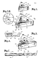
- a metal working tool generally designated 10 for use in a lathe or the like.
- Tool 10 coup rises three components, designated seat 12, cutting insert 14 and chipbreaker 16.
- the three components 12,14 and 16 are held together by the upper and lower lips 18,20, respectively, of clamping means 22.
- Cutting insert 1 4 may comprise a high strength metal or, in certain applications, other materials, such as ceramic or the like.
- Fig. 2 presents an exploded view of tool 10 depicting each of the components 12,14 and 16 thereof.
- Fig. 2 also depicts a novel fluia cooling system for tool 10 wherein coolant fluid is supplied to tool 10 via conduit 24 which engages fluid passage 25 passing through lower lip 20.
- Seat 12 is a substantially triangular planar structure affixed to lower lip 20 by bolt 19. Although bolt 19 is used in the preferred embodiment, any conventional securing means will suffice. Fluid passage 21 extends through bolt 19 and communicates with both seat fluid supply passage 26 extending from fluid intake port 28 in the lower surface (nut visible) of seat 12 and conduit 24. Seat fluid supply passage 26 extends to fluid outlet port 30 in the upper surface 32 of seat 12. Seat fluid passage 26 also communicates with seat fluid discharge passage 34 which supplies coolant fluid to fluid exit port 36 located in the flank 38 of seat 12.
- Cutting insert 14 is a substantially triangular planar structure having an insert fluid supply passage 40 extending from fluid intake port 42 located in the lower surface thereof (not visible) to outlet port 44 located in the upper surface 46 thereof.
- Intake port 42 is generally disposed to receive coolant fluid from fluid outlet port 30.
- Insert fluid supply passage 40 also communicates with insert fluid discharge passage 48 which supplies coolant fluid to fluid exit port 50 located in the flank 52 of cutting insert 14.
- upper surface 46 and flank 52 join to form edge 54.
- upper surface 46 joins flank 52' (not shown) to form edge 54'
- upper surface 46 joins flank 52" (not shown) to form edge 54".
- These edges 54, 54' and 54" are the upper edges of insert 14.
- a portion of each edge 54, 54' and 54" is a metal working edge, generally designated 56, 56' and 56", respectively.
- Metal working edges 56, 56' and 56" lie within the respective metal working regions generally designated 55, 55' and 55".
- Metal working regions 55, 55' and 55" encompass portions of the upper surface 46 and flanks 52, 52' and 52" forming metal working edges 56, 56' and 56".
- Metal working region 55 is further depicted in Fig. 2c.
- Chipbreaker 16 is a substantially triangular planar structure having a chamber 58 centrally disposed therewithin to receive fluid from outlet port 44.
- Chamber 58 is a depression extending partially through chipbreaker 16 and may be of any convenient geometry.
- Chipbreaker fluid discharge passages 60,61 communicate with chamber 58 and with exit ports 62,63, respectively. It should be recognized that although two passages 60,61 are shown, one or more of such passages may be used.
- the present invention provides a novel arrangement of fluid passages and fluid exit ports to direct coolant fluid streams proximate metal working region 55.
- pressurized coolant flows from a coolant source (not shown) through conduit 24 and fluid passages 25 and 21 into intake port 28 and seat fluid supply passage 26.
- a portion of the fluid flowing through seat fluid supply passage 26 is diverted into seat fluid discharge passage 34 and expelled through fluid exit port 36.
- Seat fluid supply passage 34 and fluid exit port 3 b are oriented so that the central axis s thereof projects proximate metal working region 55.
- fluid ejected from fluid exit port 36 is directed proximate metal working region 55 to conduct heat therefrom.
- Fig. 2a is a horizontal cross section of cutting insert 14 showing the orientation of insert fluid discharge passages 48, 48' and 48" and of exit ports 50, 50' and 50". As can be seen, this orientation is such that the fluid stream emanating from exit port 50 will be projected across a portion of flank 52.
- Fig. 2b is a cross sectional view, broken away, along line 2B-2B of cutting insert 14 further depicting the orientation of insert fluid discharge passage 48.
- insert fluid discharge passage 48 may communicate with insert fluid supply passage 40 proximate the lower surface 41 of cutting insert 14 and project upwardly through the interior of cutting insert 14 to exit port 50.
- fluid passing through insert fluid discharge passage 48 and fluid exit port 50 will be expelled in a stream directed upward and approximately across flank 5t proximate metal working region 55.
- a second portion of the fluid flowing through insert fluid discharge passage 40 flows through outlet port 44 into chamber 58 of chipbreaker 16.
- coolant fluid is directed via chipbreaker fluid discharge passages 60,61 to exit ports 62,63, respectively.
- Chipbreaker fluid discharge passages 60,61 and exit ports 62,63 are oriented so that the projected central axes thereof pass proximate working region 55.
- a fluid stream is directed along the upper surface 46 of insert 14 to metal working edge 56, providing still another stream of coolant fluid proximate metal working region 55.
- Fig. 2 discloses not only metal working edges 56, 56' and 5b" but also insert fluid discharge passages 48, 48' and 48" leading to fluid exit ports 50, 50' and 50".
- clamping means 22 is constructed so that the fluid exit ports associated with the unused metal working edges are blocked to prevent fluid flow therethrough.
- the discussion hereinabove is equally applicable to any of the metal working regiops 55, 55' or 55" and the insert fluid discharge passage and exit port associated therewith.
- a novel bimetallic structure for insert 14 has been invented for use with the aforementioned fluid cooling system.
- This preferred embodiment depicted in Fig. 3 comprises a bimetallic substantially planar metal working insert 14' having a peripheral outer structural component b 6 encompassing an inner structural component 68.
- Outer structural component 66 is made from a material such as carbide or tungsten or the like suitable for machining metal.
- Inner structural component 68 is made from a material having good thermal conductivity such as copper, silver, or the like.
- the invention provides a cutting insert 14' having the cutting ability of carbide with enhanced ability to conduct heat from the working region 55 thereof.
- a centrally located cavity 70 of convenient geometry is provided in outer structural conponent 66. This may be provided by electric discharge machining, casting or other suitable means.
- Inner structural component 68 is then provided by electroforming copper or other suitable material into cavity 70.
- two mutually opposed cavities 70,70' may be formed in the lower 41 and upper 46 surfaces of outer structural component 66 as depicted in Fig. 4. Copper or other thermally conductive material may then be electroformed therewithin in a conventional manner.
- electroforming is the preferred means for forming inner structural component 68, other conventional means for attaching inner structural component 68 to outer structural component 66 are also acceptable.
- Another embodiment of the invention provides for cavity 70 to extend completely through outer structural component 66.
- An inner structural component of copper or other highly thermally conductive material 68 may then be brazed or otherwise bonded therewithin to form an integral planar cutting insert 14'.
- the novel bimetallic structure of the preferred embodiment provides that the higher thermal conductivity of the inner structural component 68 serves to conduct heat away from the metal working region 55 more readily than was possible with prior art inserts, thereby increasing the life and versatility of the cutting insert 14'. Since the invention provides a more efficient metal working tool, the forces exerted upon a workpiece may be reduced in a given metal working operation, thereby serving to increase the service life of lathes and other machines wherein the invention is util ized.
- the bimetallic structure of cutting insert 14' is compatible with the coolant fluid system described hereinbefore and depicted in both Fig. 3 and Fig. 5.
- inner structural conponent 68 is electroformed into cavity 70
- the electroforming process is completed to provide an integral, bimetallic cutting insert 14' wherein the appropriate fluid passages and ports are then created.
- bimetallic cutting insert 14' utilizes the fluid cooling system described hereinabove, the enhanced utility of insert 14' is not limited to such application and bimetallic insert 14' will provide enhanced means for conducting heat away from working region 55 regardless of whether internal fluid cooling is used.
- Fig. 6 depicts another aspect of the preferred embodiment.
- tool 10 is utilized for electrical resistance hot machining.
- a variable current source 86 capable of supplyi ng high current (AC or DC) on the order of 1000 amperes at approximately 1 volt has first 88 and second 90 electrodes connected, respectively, to clamping means 22 and to workpiece 84.
- first 88 and second 90 electrodes connected, respectively, to clamping means 22 and to workpiece 84.
- heat built up in metal working region 55 is effectively dissipated by structural element 68 and by the fluid cooling system as described hereinabove.
- Heat built up in shear zone 82 is not so effectively dissipated since such high strength materials typically are relatively poor heat conductors and since the shear zone thereof is not bathed by fluid.
- the temperature of shear zone 82 rises above that of metal working region 55.
- the machinability of workpiece 84 is thus enhanced without the degree of tool wear experienced in prior-art through-the-tool electrical resistance hot machining techniques.
- Fig. 7 depicts another embodiment of the present invention.
- a bimetallic fluted drill bit generally designated 72 having metal working region 73, lands 74 and flute 76 associated therewith.
- the flute 76 is designed primarily to carry away chips rather than to cut, it may be plated with a relatively soft but highly thermally conductive material such as copper or the tike. This provides the tool 72 with an enhanced capability to conduct heat away from the working region 73.
- copper coating 78 may extend the entire length of flute 76 and onto shank 80 for optimal heat dissipating qualities.
- the original metal working qualities of drill bit 72 are thus retained and the heat dissipating qualities thereof significantly enhanced.
- the aforedescribed embodiment is not limited to drill bits but is equally applicable to any fluted machining tool such as broache;, taps, milling cutters, reamers and the like.
- the bimetallic structure may comprise a highly conductive body affixed to a metal cutting tip.
- novel fluid cooling system disclosed herein is useful with metallic cutting tools or cutting inserts comprised of virtually any heat conducting material, and is not limited to the bimetallic structure defined herein.
Landscapes
- Engineering & Computer Science (AREA)
- Mechanical Engineering (AREA)
- Cutting Tools, Boring Holders, And Turrets (AREA)
- Auxiliary Devices For Machine Tools (AREA)
- Drilling Tools (AREA)
Applications Claiming Priority (2)
| Application Number | Priority Date | Filing Date | Title |
|---|---|---|---|
| US40501282A | 1982-08-04 | 1982-08-04 | |
| US405012 | 1982-08-04 |
Publications (2)
| Publication Number | Publication Date |
|---|---|
| EP0100376A2 true EP0100376A2 (de) | 1984-02-15 |
| EP0100376A3 EP0100376A3 (de) | 1984-08-29 |
Family
ID=23601932
Family Applications (1)
| Application Number | Title | Priority Date | Filing Date |
|---|---|---|---|
| EP82110670A Withdrawn EP0100376A3 (de) | 1982-08-04 | 1982-11-18 | Werkzeug für Metallbearbeitung |
Country Status (5)
| Country | Link |
|---|---|
| EP (1) | EP0100376A3 (de) |
| JP (1) | JPS5942205A (de) |
| AU (1) | AU9091882A (de) |
| DK (1) | DK75283A (de) |
| NO (1) | NO156819C (de) |
Cited By (33)
| Publication number | Priority date | Publication date | Assignee | Title |
|---|---|---|---|---|
| EP0138031A3 (en) * | 1983-10-14 | 1986-07-30 | Rockwell International Corporation | Metal-working tool using electrical heating |
| US4695208A (en) * | 1985-11-14 | 1987-09-22 | Yankoff Gerald K | Tool holder |
| WO1991012913A1 (en) * | 1990-02-26 | 1991-09-05 | Cleveland State University | A cutting insert, a tool holder therefor and a method of machining with fluid jet assistance |
| EP0599393A1 (de) * | 1992-11-20 | 1994-06-01 | Plansee Tizit Gesellschaft M.B.H. | Schneidwerkzeug |
| US5340242A (en) * | 1992-09-25 | 1994-08-23 | Kennametal Inc. | Chip-breaking toolholder with adjustable orifice cap |
| EP0636442A1 (de) * | 1993-07-30 | 1995-02-01 | Iscar Ltd. | Ein Metallschneidewerkzeug |
| US5439327A (en) * | 1991-09-27 | 1995-08-08 | Iscar Ltd. | Metal cutting tool |
| US5775854A (en) * | 1991-09-27 | 1998-07-07 | Iscar Ltd. | Metal cutting tool |
| US5901623A (en) * | 1994-08-09 | 1999-05-11 | The Edison Materials Technology Center | Cryogenic machining |
| DE19903276A1 (de) * | 1999-01-28 | 2000-08-10 | Maier Kg Andreas | Spanabhebendes Werkzeug und Verfahren zu seiner Herstellung |
| WO2008014933A1 (de) | 2006-07-29 | 2008-02-07 | Hartmetall-Werkzeugfabrik Paul Horn Gmbh | Werkzeugsystem |
| WO2008088627A1 (en) * | 2007-01-18 | 2008-07-24 | Kennametal Inc. | Metal cutting system for effective coolant delivery |
| US7625157B2 (en) | 2007-01-18 | 2009-12-01 | Kennametal Inc. | Milling cutter and milling insert with coolant delivery |
| CN102350536A (zh) * | 2007-01-18 | 2012-02-15 | 钴碳化钨硬质合金公司 | 具有冷却剂传送的铣削镶片以及铣刀 |
| US8596935B2 (en) | 2010-10-08 | 2013-12-03 | TDY Industries, LLC | Cutting tools and cutting inserts including internal cooling |
| US8840342B2 (en) | 2010-09-02 | 2014-09-23 | Kennametal Inc. | Finishing cutting insert |
| EP2373452A4 (de) * | 2009-01-06 | 2015-01-07 | Kennametal Inc | Schneideeinsatz mit kühlmittelausgabe sowie verfahren zur herstellung des schneideeinsatzes |
| US9101985B2 (en) | 2007-01-18 | 2015-08-11 | Kennametal Inc. | Cutting insert assembly and components thereof |
| US9180650B2 (en) | 2010-10-08 | 2015-11-10 | Kennametal Inc. | Cutting tool including an internal coolant system and fastener for a cutting tool including an internal coolant system |
| EP2946857A1 (de) * | 2014-05-19 | 2015-11-25 | Sandvik Intellectual Property AB | Drehwerkzeughalter und Schneidwerkzeugeinsatz |
| CN106270585A (zh) * | 2016-09-19 | 2017-01-04 | 上海理工大学 | 带过渡曲面的内循环冷却刀具及冷却方法 |
| EP2691202B1 (de) | 2011-03-28 | 2017-12-20 | Hartmetall-Werkzeugfabrik Paul Horn GmbH | Halter zur spanenden Bearbeitung eines Werkstücks sowie ein Werkstück mit einem solchen Halter mit seitlichen Kühlmittelaustritten. |
| US20170368612A1 (en) * | 2015-01-23 | 2017-12-28 | Mitsubishi Materials Corporation | Tool holder |
| US9895755B2 (en) | 2014-12-09 | 2018-02-20 | Kennametal Inc. | Cutting insert with internal coolant passages and method of making same |
| US10007246B2 (en) | 2014-12-02 | 2018-06-26 | Caterpillar Inc. | Machining tool utilizing a supercritical coolant |
| JP2018134722A (ja) * | 2017-02-23 | 2018-08-30 | 株式会社豊田中央研究所 | 切削工具 |
| US10413977B2 (en) * | 2015-11-12 | 2019-09-17 | 5Me Ip, Llc | Temperature management for a cryogenically cooled boring tool |
| US10654116B2 (en) * | 2017-10-25 | 2020-05-19 | Tungaloy Corporation | Cutting insert, metal spacer and holder |
| US11440101B2 (en) * | 2018-04-30 | 2022-09-13 | Hartmetall-Werkzeugfabrik Paul Horn Gmbh | Tool for machining a workpiece |
| US11648613B2 (en) | 2017-10-12 | 2023-05-16 | Hartmetall-Werkzeugfabrik Paul Hom GmbH | Holder for a broaching tool |
| US11673239B2 (en) | 2020-02-13 | 2023-06-13 | Milwaukee Electric Tool Corporation | Tool bit having a bimetal tip |
| DE102022107054A1 (de) | 2022-03-25 | 2023-09-28 | Gühring KG | Werkzeug |
| US12172220B2 (en) | 2019-02-08 | 2024-12-24 | National University Corporation Tokai National Higher Education And Research System | Cutting insert and cutting tool |
Families Citing this family (3)
| Publication number | Priority date | Publication date | Assignee | Title |
|---|---|---|---|---|
| SE510284C2 (sv) * | 1996-11-18 | 1999-05-10 | Sandvik Ab | Invändigt kylbart skär för spånavskiljande bearbetning |
| JP5743272B2 (ja) * | 2011-08-30 | 2015-07-01 | 住友電工ハードメタル株式会社 | 逃げ面内部給油孔付き超高圧焼結体工具 |
| JP6314636B2 (ja) * | 2014-05-08 | 2018-04-25 | 株式会社デンソー | 切削加工装置 |
Family Cites Families (4)
| Publication number | Priority date | Publication date | Assignee | Title |
|---|---|---|---|---|
| DE504275C (de) * | 1926-12-14 | 1930-08-04 | Alexander Jgnatieff | Waermeableitungseinrichtung an Werkzeugen |
| AT218821B (de) * | 1958-12-20 | 1961-12-27 | Spanabhebendes Werkzeug | |
| FR1279749A (fr) * | 1961-01-16 | 1961-12-22 | Refroidissement des outils coupants par combinaison de deux buses réglables horizontale et verticale projetant un lubrifiant refroidisseur sous le copeau | |
| SE429934B (sv) * | 1979-02-07 | 1983-10-10 | Sandvik Ab | Skerverktyg med inbyggd kylmedietillforsel |
-
1982
- 1982-11-18 EP EP82110670A patent/EP0100376A3/de not_active Withdrawn
- 1982-11-26 AU AU90918/82A patent/AU9091882A/en not_active Abandoned
- 1982-12-17 NO NO824261A patent/NO156819C/no unknown
-
1983
- 1983-02-22 DK DK75283A patent/DK75283A/da not_active Application Discontinuation
- 1983-07-27 JP JP58136009A patent/JPS5942205A/ja active Pending
Cited By (47)
| Publication number | Priority date | Publication date | Assignee | Title |
|---|---|---|---|---|
| EP0138031A3 (en) * | 1983-10-14 | 1986-07-30 | Rockwell International Corporation | Metal-working tool using electrical heating |
| US4695208A (en) * | 1985-11-14 | 1987-09-22 | Yankoff Gerald K | Tool holder |
| WO1991012913A1 (en) * | 1990-02-26 | 1991-09-05 | Cleveland State University | A cutting insert, a tool holder therefor and a method of machining with fluid jet assistance |
| US5439327A (en) * | 1991-09-27 | 1995-08-08 | Iscar Ltd. | Metal cutting tool |
| US5775854A (en) * | 1991-09-27 | 1998-07-07 | Iscar Ltd. | Metal cutting tool |
| US5340242A (en) * | 1992-09-25 | 1994-08-23 | Kennametal Inc. | Chip-breaking toolholder with adjustable orifice cap |
| EP0599393A1 (de) * | 1992-11-20 | 1994-06-01 | Plansee Tizit Gesellschaft M.B.H. | Schneidwerkzeug |
| EP0636442A1 (de) * | 1993-07-30 | 1995-02-01 | Iscar Ltd. | Ein Metallschneidewerkzeug |
| US5901623A (en) * | 1994-08-09 | 1999-05-11 | The Edison Materials Technology Center | Cryogenic machining |
| DE19903276A1 (de) * | 1999-01-28 | 2000-08-10 | Maier Kg Andreas | Spanabhebendes Werkzeug und Verfahren zu seiner Herstellung |
| WO2008014933A1 (de) | 2006-07-29 | 2008-02-07 | Hartmetall-Werkzeugfabrik Paul Horn Gmbh | Werkzeugsystem |
| US8137034B2 (en) | 2006-07-29 | 2012-03-20 | Hartmetall-Werkzeugfabrik Paul Horn Gmbh | Tool system |
| WO2008088627A1 (en) * | 2007-01-18 | 2008-07-24 | Kennametal Inc. | Metal cutting system for effective coolant delivery |
| US7625157B2 (en) | 2007-01-18 | 2009-12-01 | Kennametal Inc. | Milling cutter and milling insert with coolant delivery |
| CN102350536A (zh) * | 2007-01-18 | 2012-02-15 | 钴碳化钨硬质合金公司 | 具有冷却剂传送的铣削镶片以及铣刀 |
| RU2445189C2 (ru) * | 2007-01-18 | 2012-03-20 | Кеннаметал Инк. | Металлорежущая система для эффективной подачи охлаждающей текучей среды |
| CN101600569B (zh) * | 2007-01-18 | 2013-04-24 | 钴碳化钨硬质合金公司 | 用于冷却剂有效传送的金属切削系统 |
| CN102350536B (zh) * | 2007-01-18 | 2013-10-02 | 钴碳化钨硬质合金公司 | 具有冷却剂传送的铣削镶片以及铣刀 |
| CN102350537B (zh) * | 2007-01-18 | 2013-10-02 | 钴碳化钨硬质合金公司 | 具有冷却剂传送的铣削镶片以及铣刀 |
| US9108253B2 (en) | 2007-01-18 | 2015-08-18 | Kennametal Inc. | Roughing cutting insert |
| US9101985B2 (en) | 2007-01-18 | 2015-08-11 | Kennametal Inc. | Cutting insert assembly and components thereof |
| EP2373452A4 (de) * | 2009-01-06 | 2015-01-07 | Kennametal Inc | Schneideeinsatz mit kühlmittelausgabe sowie verfahren zur herstellung des schneideeinsatzes |
| US9095913B2 (en) | 2010-09-02 | 2015-08-04 | Kennametal Inc. | Cutting inserts |
| US8840342B2 (en) | 2010-09-02 | 2014-09-23 | Kennametal Inc. | Finishing cutting insert |
| US8596935B2 (en) | 2010-10-08 | 2013-12-03 | TDY Industries, LLC | Cutting tools and cutting inserts including internal cooling |
| US9180650B2 (en) | 2010-10-08 | 2015-11-10 | Kennametal Inc. | Cutting tool including an internal coolant system and fastener for a cutting tool including an internal coolant system |
| EP2691202B1 (de) | 2011-03-28 | 2017-12-20 | Hartmetall-Werkzeugfabrik Paul Horn GmbH | Halter zur spanenden Bearbeitung eines Werkstücks sowie ein Werkstück mit einem solchen Halter mit seitlichen Kühlmittelaustritten. |
| CN105081376A (zh) * | 2014-05-19 | 2015-11-25 | 山特维克知识产权股份有限公司 | 车刀刀架和切削刀具刀片 |
| EP2946857B1 (de) | 2014-05-19 | 2019-10-16 | Sandvik Intellectual Property AB | Drehwerkzeughalter und Schneidwerkzeugeinsatz |
| US9925596B2 (en) | 2014-05-19 | 2018-03-27 | Sandvik Intellectual Property Ab | Turning tool holder and cutting tool insert |
| EP2946857A1 (de) * | 2014-05-19 | 2015-11-25 | Sandvik Intellectual Property AB | Drehwerkzeughalter und Schneidwerkzeugeinsatz |
| CN105081376B (zh) * | 2014-05-19 | 2018-09-18 | 山特维克知识产权股份有限公司 | 车刀刀架和切削刀具刀片 |
| US10007246B2 (en) | 2014-12-02 | 2018-06-26 | Caterpillar Inc. | Machining tool utilizing a supercritical coolant |
| US9895755B2 (en) | 2014-12-09 | 2018-02-20 | Kennametal Inc. | Cutting insert with internal coolant passages and method of making same |
| US20170368612A1 (en) * | 2015-01-23 | 2017-12-28 | Mitsubishi Materials Corporation | Tool holder |
| US10307827B2 (en) * | 2015-01-23 | 2019-06-04 | Mitsubishi Materials Corporation | Tool holder |
| US10413977B2 (en) * | 2015-11-12 | 2019-09-17 | 5Me Ip, Llc | Temperature management for a cryogenically cooled boring tool |
| CN106270585A (zh) * | 2016-09-19 | 2017-01-04 | 上海理工大学 | 带过渡曲面的内循环冷却刀具及冷却方法 |
| CN106270585B (zh) * | 2016-09-19 | 2018-05-22 | 上海理工大学 | 带过渡曲面的内循环冷却刀具及冷却方法 |
| JP2018134722A (ja) * | 2017-02-23 | 2018-08-30 | 株式会社豊田中央研究所 | 切削工具 |
| US11648613B2 (en) | 2017-10-12 | 2023-05-16 | Hartmetall-Werkzeugfabrik Paul Hom GmbH | Holder for a broaching tool |
| US10654116B2 (en) * | 2017-10-25 | 2020-05-19 | Tungaloy Corporation | Cutting insert, metal spacer and holder |
| US11440101B2 (en) * | 2018-04-30 | 2022-09-13 | Hartmetall-Werkzeugfabrik Paul Horn Gmbh | Tool for machining a workpiece |
| US12172220B2 (en) | 2019-02-08 | 2024-12-24 | National University Corporation Tokai National Higher Education And Research System | Cutting insert and cutting tool |
| US11673239B2 (en) | 2020-02-13 | 2023-06-13 | Milwaukee Electric Tool Corporation | Tool bit having a bimetal tip |
| US12122019B2 (en) | 2020-02-13 | 2024-10-22 | Milwaukee Electric Tool Corporation | Tool bit having a bimetal tip |
| DE102022107054A1 (de) | 2022-03-25 | 2023-09-28 | Gühring KG | Werkzeug |
Also Published As
| Publication number | Publication date |
|---|---|
| EP0100376A3 (de) | 1984-08-29 |
| NO156819B (no) | 1987-08-24 |
| JPS5942205A (ja) | 1984-03-08 |
| AU9091882A (en) | 1984-02-09 |
| DK75283A (da) | 1984-02-05 |
| DK75283D0 (da) | 1983-02-22 |
| NO156819C (no) | 1987-12-02 |
| NO824261L (no) | 1984-02-06 |
Similar Documents
| Publication | Publication Date | Title |
|---|---|---|
| US4535216A (en) | Metal-working tool using electrical heating | |
| JPS5942205A (ja) | 金属加工用工具 | |
| Narutaki et al. | Study on machining of titanium alloys | |
| US8596935B2 (en) | Cutting tools and cutting inserts including internal cooling | |
| US4340327A (en) | Tool support and drilling tool | |
| US4072438A (en) | Insert type drill and insert therefor | |
| CN103097057B (zh) | 具有内部冷却剂递送的切削镶片和使用其的切削组件 | |
| US4302135A (en) | Rotary cutting tool | |
| WO2012047456A1 (en) | Cutting tool with a coolant system and fastener therefor | |
| JPH03234408A (ja) | スローアウェイ式ドリル | |
| US2641047A (en) | Cutting tool | |
| US2848790A (en) | Coolant directing cutting tool assembly | |
| JPH032347A (ja) | 窒素含有サーメット合金 | |
| CN112453508A (zh) | 一种复合材料孔加工pcd钻铣倒角刀具 | |
| EP1609551A1 (de) | Führungsleisten für Bohrköpfe | |
| CN211489684U (zh) | 一种用于加工含能材料的可调式多切削刃车削刀具 | |
| US10792738B2 (en) | Cutting tool and method of manufacturing machined product | |
| CN211727535U (zh) | 带水滴状断屑凸台的超硬螺纹加工刀片 | |
| US4555204A (en) | Metal-working tools with augmented conductivity | |
| US3249985A (en) | Cutting tool | |
| CN111347087A (zh) | 一种带有自动排屑功能的钻头 | |
| CN219541795U (zh) | 一种多台阶式钻镗刀 | |
| CN223277203U (zh) | 一种强度优秀的可转位车削刀片 | |
| CN222643391U (zh) | 焊接合金式排屑铰刀 | |
| JP2018134722A (ja) | 切削工具 |
Legal Events
| Date | Code | Title | Description |
|---|---|---|---|
| PUAI | Public reference made under article 153(3) epc to a published international application that has entered the european phase |
Free format text: ORIGINAL CODE: 0009012 |
|
| AK | Designated contracting states |
Designated state(s): BE CH DE FR GB IT LI NL SE |
|
| PUAL | Search report despatched |
Free format text: ORIGINAL CODE: 0009013 |
|
| AK | Designated contracting states |
Designated state(s): BE CH DE FR GB IT LI NL SE |
|
| 17P | Request for examination filed |
Effective date: 19850220 |
|
| 17Q | First examination report despatched |
Effective date: 19860213 |
|
| STAA | Information on the status of an ep patent application or granted ep patent |
Free format text: STATUS: THE APPLICATION IS DEEMED TO BE WITHDRAWN |
|
| 18D | Application deemed to be withdrawn |
Effective date: 19860624 |
|
| RIN1 | Information on inventor provided before grant (corrected) |
Inventor name: CASSIDENTI, MICHAEL LEROY |