EP0100264B1 - Dispositif pour la charge avec compression de solides dans un réceptacle - Google Patents
Dispositif pour la charge avec compression de solides dans un réceptacle Download PDFInfo
- Publication number
- EP0100264B1 EP0100264B1 EP83401436A EP83401436A EP0100264B1 EP 0100264 B1 EP0100264 B1 EP 0100264B1 EP 83401436 A EP83401436 A EP 83401436A EP 83401436 A EP83401436 A EP 83401436A EP 0100264 B1 EP0100264 B1 EP 0100264B1
- Authority
- EP
- European Patent Office
- Prior art keywords
- jack
- blade
- connection
- panel
- elements
- Prior art date
- Legal status (The legal status is an assumption and is not a legal conclusion. Google has not performed a legal analysis and makes no representation as to the accuracy of the status listed.)
- Expired
Links
- 239000011343 solid material Substances 0.000 title description 2
- 230000006835 compression Effects 0.000 claims description 17
- 238000007906 compression Methods 0.000 claims description 17
- 239000000463 material Substances 0.000 claims description 16
- 230000009471 action Effects 0.000 claims description 5
- 230000001154 acute effect Effects 0.000 claims description 3
- 210000003141 lower extremity Anatomy 0.000 claims description 2
- 210000001364 upper extremity Anatomy 0.000 claims 2
- 210000003414 extremity Anatomy 0.000 claims 1
- 101001017827 Mus musculus Leucine-rich repeat flightless-interacting protein 1 Proteins 0.000 description 10
- 238000000034 method Methods 0.000 description 4
- 230000008901 benefit Effects 0.000 description 3
- 239000007787 solid Substances 0.000 description 3
- 238000010276 construction Methods 0.000 description 2
- 230000000694 effects Effects 0.000 description 2
- 150000001875 compounds Chemical class 0.000 description 1
- 238000011109 contamination Methods 0.000 description 1
- 230000006866 deterioration Effects 0.000 description 1
- 238000006073 displacement reaction Methods 0.000 description 1
- 239000010791 domestic waste Substances 0.000 description 1
- 230000006872 improvement Effects 0.000 description 1
- 238000009434 installation Methods 0.000 description 1
- 230000014759 maintenance of location Effects 0.000 description 1
- 210000000056 organ Anatomy 0.000 description 1
- 230000008569 process Effects 0.000 description 1
- 230000003014 reinforcing effect Effects 0.000 description 1
- 230000033764 rhythmic process Effects 0.000 description 1
- 230000001360 synchronised effect Effects 0.000 description 1
- 230000007704 transition Effects 0.000 description 1
- 239000002699 waste material Substances 0.000 description 1
Images

Classifications
-
- B—PERFORMING OPERATIONS; TRANSPORTING
- B65—CONVEYING; PACKING; STORING; HANDLING THIN OR FILAMENTARY MATERIAL
- B65F—GATHERING OR REMOVAL OF DOMESTIC OR LIKE REFUSE
- B65F3/00—Vehicles particularly adapted for collecting refuse
- B65F3/14—Vehicles particularly adapted for collecting refuse with devices for charging, distributing or compressing refuse in the interior of the tank of a refuse vehicle
- B65F3/20—Vehicles particularly adapted for collecting refuse with devices for charging, distributing or compressing refuse in the interior of the tank of a refuse vehicle with charging pistons, plates, or the like
- B65F3/207—Vehicles particularly adapted for collecting refuse with devices for charging, distributing or compressing refuse in the interior of the tank of a refuse vehicle with charging pistons, plates, or the like guided by tracks, channels, slots or the like provided on the vehicle
Definitions
- the invention relates to an improved device for loading, with compression, different solids in a receptacle. It relates in particular to the loading of materials, in particular garbage or waste, domestic or industrial, into a bucket.
- the new device is applicable to different containers or dumpsters, fixed or mobile, and, more specifically, to refuse collection vehicles.
- the devices of the type concerned by the present invention comprise mobile means, generally known by the name of shovel or flap, for pushing the materials into the receptacle; these means, mounted in a loading hopper, are moved by motor means placed symmetrically on either side, in the width direction, of the flap.
- guides were provided for these mobile means of thrust, so as to impose the desired trajectory on the latter, during work.
- US Patent No. 3220586 where the guides have an inclined portion and a horizontal, and define the operation of the flap in a 3- time.
- U improvement was carried out thereafter, according to publication No. 2436092 of the French patent application: the shutter and its jacks are integral with a sliding beam on a uniformly curved guide, and the operating cycle is 4 times .
- the present invention provides significant advantages over the corresponding prior art, both with regard to the construction of the device and the effectiveness thereof.
- the invention allows, in fact, the loading with high compression of solid materials of all kinds, of high hourly tonnage, with a device much lighter than those of known devices; thus can orr gain, for example, 30% on the weight of the device while treating the same hourly weight of household waste, with an equivalent compression or even stronger than in the past.
- Another advantage of the device according to the invention lies in the fact that it is possible to load materials into the hopper at any time, during operation, which resembles the device to continuous devices.
- the invention gives excellent results in the operation of the loading means with compression according to a 4-stroke cycle, but it can be applied as well to a milker of different rhythm.
- the mobile means for pushing and compressing the materials to be loaded are constituted by two elements, both moving in lateral guides and articulated to each other, so as to allow their translation along the guides, as well as their reciprocal pivoting.
- the mounting is such that, during operation, these means move simultaneously, both, in a triangular configuration with respect to the means which produce this movement.
- the device for loading materials according to the invention is of the type with compression in a receptacle from a hopper, comprising two compression elements formed by an upper element and a lower element, which can pivot one by relative to the other, around a common pivot axis, located at the lower part of the upper element, these two elements being able each moreover to pivot around a sliding axis in lateral guides, this axis being, for the upper element, located at the upper end thereof; first drive means, for example jacks moving all of the two elements in the lateral guides, and second drive means, in particular jacks making one element pivot relative to the other, these second drive means being connected to the upper end of the upper element (such a device is known from DE-A N o 2908208).
- This device is characterized in that the first and second drive means are attached to the upper end of the lower element by an articulation which slides in the lateral guides, and that the pivot axis common to the two elements is located outside lateral guides.
- Each of the two elements, forming the mobile loading means has a roller in the guide, at its upper end; while the articulation between them is outside the planes passing through the guides, in particular below these planes.
- this last articulation connects the lower extremity of the upper element to the body of the lower element between approximately 1 / 3and 1 ⁇ 2 of the length of the latter counted from its upper end.
- the drive means most often jacks, are, according to the invention, two in number arranged at the sides of the atheros of the mobile loading elements.
- all the two pairs of motor means are connected to the upper end or head of the lower loading element; one of these pairs has its opposite end connected to the upper end of the upper element, on the guide path, while the opposite end of the second pair of motor means is articulated at the top of the wall of the device, especially on the hopper door articulation.
- the loading elements are solid panels, the front face of which, that is to say that which faces the interior of the receptacle, preferably has a profile suitable for the pushing and compression work to be carried out.
- the lower element constitutes a solid panel only in its lower part, below its articulation with the upper element.
- the top of this lower element is notched, which makes it possible to load the hopper even during the operation of the device.
- the preferred shape of the lower element is such that the section thereof by a vertical plane, parallel to the plane passing through the guides, is substantially triangular.
- the upper element it is advantageous that it has a stepped profile, reinforcing this element and helping to retain the treated materials, when the hopper is opened.
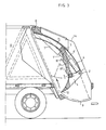
- FIG. 3 shows a set of two elements, 1 and 6, for loading, moving in the guide 11, with their jacks 4 and 7, all mounted in a hopper of conventional type 9, closed at the top by flanks 14. These organs are found in all the figures, but are best visible in FIG. 3. From fig. 5 it is understood that there is in fact a pair of guides 11, a pair of jacks 4 and one of jacks 7, as well as a pair of each of the joints. However, for the simplification of the description, we speak of only one of each of these bodies.
- the invention has this originality, compared to the known technique, that the two thrust and compression elements, 1 and 6, are articulated to each other outside of the guide 11, at 3, while the two jacks 4 and 7 are both attached to the same joint 2 at the upper end of the element 1.
- the new structure includes the guide or raceway 11, curved in the embodiment shown, but which may be straight; in this guide, at 5, rolls a roller carried by the upper edge of the movable panel 6, which constitutes the upper element of the compression loading means.
- the flap 1 has a general U-shape: its active part 1 a-1 b, which pushes the materials from the right to the left according to FIGS. 1, 2, 3, 4, 7 and 8, is carried by two arms 1 c and 1 ′ c visible in FIG. 6. These arms rotate around the axis 3 which hinges them on the compression element 6; they also pivot around the axes 2,2 ′, on the guides 11, where the jacks 4 and 7 are attached. This results in an empty space 15 above the axis 3, through which materials can be introduced. in the hopper, regardless of the position of the flap 1.
- the active part 1 a-1 b of the shutter 1 is preferably of a box construction which allows high forces to be exerted by means of a light weight shutter.
- the height of the arms 1 c and 1'c is generally about 0.75 to 4 times that of the active part 1 a-1 b, and preferably 1 to 3 times.
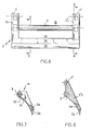
- fig. 8 being a vertical section of the arm 1'c and of the active parts 1 a-1 b, by the plane Z-Z, makes it possible to see both the arm 1'c and the part 1 a-1 b in section (hatched).
- the bottom of the panel 6 is articulated in 3 to the flap 1, which gives a compound loading assembly, 1 -6, deformable under the action of the associated jacks.
- the top 5 of the panel 6 is connected to the head 2 of the shutter 1 by a jack 4; the rod 4 'of this jack is articulated at 5 and the cylinder at 2. In this way, as the two ends, 2 and 5, of the jack 4 are located in the path 11, this jack remains always aligned parallel to a tangent to the path 11.
- a second cylinder, 7, is mounted between the side 14 of the hopper and the head 2 of the flap 1.
- the end of the cylinder 7 is articulated at 8 on the side of the device, while the rod 7 'of this cylinder is connected to the upper end 2 of the shutter 1, that is to say at the same point where the bottom of the cylinder of the first jack 4 is articulated.
- the assembly thus formed of flap 1, panel 6, and jack 4, constitutes a triangle, deformable under the action of jack 4, for each of the positions determined by jack 3, when the latter immobilizes the joint 2.
- the jacks are preferably hydraulic for a device on a vehicle, but can be electric, especially in a fixed installation.
- the preferred profile of the flap 1 is substantially a triangle with an obtuse angle at the top 3, and an acute angle at the lower end 12.
- the obtuse angle is preferably about 100 to 125 °, while that of the end 12 measures 10 to 35 °.
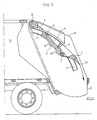
- the elements 1 and 6 occupy their highest place on the raceway or guide 11, that is to say that the rollers of the joints 2 and 5 respectively are in their highest positions.
- the jacks 4 and 7 are completely retracted, which means that the flap 1 and the panel 6 are aligned along the guide 11, one in the extension of the other; the angle between 1 and 6 is here the smallest of all that these elements can make between them during work.
- the situation according to fig. 1 is the start of the first stage of the operating cycle. This time lies in the expansion of the pressing cylinder 7 which pushes the joint 2 down the shirt 11. This results in the displacement of the assembly 1-4-6 backwards and downwards, as indicated in the arrow starting from the end 12 in FIG. 1.
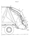
- the first step of the cycle consists in passing the assembly 1-4-6 in the position of fig. 2, that is to say until the end 12 of the shutter 1 arrives at the bottom of the hopper 9.
- the inlet of the receptacle 13 is closed by the panel 6 and the shutter 1 , as shown in fig. 2.
- due to the special shape of the shutter 1, described above there remains a free passage 15 between the axis 2 and the active part 1a-1b of the shutter 1.
- the presence of the free space 15 is an originality of the invention; it brings the advantage of being able to continue loading the hopper even during the stage of FIG. 2, which - in the devices of the known technique - corresponds to the charging stop.
- the second stage of the operating cycle is the transition from the situation according to fig. 2 to that of FIG. 3.
- the rod 7 'of the jack 7 being fully extended, it is left in this state, to maintain the joint 2 in place of FIG. 2.
- Actuate the actuator 4, the rod 4 'of which then pushes upwards the articulation 5, which drives upwards the upper edge of the panel 6.
- the triangle 1 -4-6 is in the process of deformation and produces the work of loading the materials from the hopper 9 into the receptacle 13: the shutter 1 pivots around the joint 2 in the direction of the needles a watch along the path indicated by an arrow drawn near the bottom of the hopper 9 (fig.
- the third stage of the cycle begins from the moment when the elements of the device have reached the position of FIG. 3.
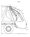
- the rod 7 'of the jack 7 is then retracted, the jack 4 remaining expanded: the two elements, 1 and 6, are then moved upwards, in the direction of the inlet of the receptacle 13, like the shows the arrow in fig. 3. It is the compression phase which takes place, while the assembly tends towards the position of FIG. 4.
- the rod 7 ′ of the jack 7 being retracted, the configuration of FIG. 4, or the end of loading with compression.
- the rod 4 ′ of the jack 4 is retracted, which causes the shutter 1 to pivot around the articulation 2 in the opposite direction to that of the second cycle time; the trajectory of the flap 1 is shown by an arrow in FIG. 4. This is the fourth time in the cycle, returning to the rest and opening position in fig. 1.
- the jacks 4 and 7 are mounted on the sides of the device, outside the hopper 9.
Landscapes
- Engineering & Computer Science (AREA)
- Mechanical Engineering (AREA)
- Refuse Collection And Transfer (AREA)
- Refuse-Collection Vehicles (AREA)
- Auxiliary Devices For And Details Of Packaging Control (AREA)
- Processing Of Solid Wastes (AREA)
- Basic Packing Technique (AREA)
- Filling Or Emptying Of Bunkers, Hoppers, And Tanks (AREA)
- Vehicle Cleaning, Maintenance, Repair, Refitting, And Outriggers (AREA)
Priority Applications (1)
| Application Number | Priority Date | Filing Date | Title |
|---|---|---|---|
| CA000441696A CA1220012A (en) | 1983-07-12 | 1983-11-22 | Process and means for the construction of wood dwellings |
Applications Claiming Priority (2)
| Application Number | Priority Date | Filing Date | Title |
|---|---|---|---|
| FR8212876 | 1982-07-23 | ||
| FR8212876A FR2537554B1 (fr) | 1982-07-23 | 1982-07-23 | Dispositif pour la charge avec compression de solides dans un receptacle |
Publications (2)
| Publication Number | Publication Date |
|---|---|
| EP0100264A1 EP0100264A1 (fr) | 1984-02-08 |
| EP0100264B1 true EP0100264B1 (fr) | 1986-01-29 |
Family
ID=9276253
Family Applications (1)
| Application Number | Title | Priority Date | Filing Date |
|---|---|---|---|
| EP83401436A Expired EP0100264B1 (fr) | 1982-07-23 | 1983-07-12 | Dispositif pour la charge avec compression de solides dans un réceptacle |
Country Status (14)
| Country | Link |
|---|---|
| US (1) | US4551055A (es) |
| EP (1) | EP0100264B1 (es) |
| JP (1) | JPS5974801A (es) |
| AU (1) | AU565401B2 (es) |
| BE (1) | BE897326A (es) |
| BR (1) | BR8303927A (es) |
| CA (1) | CA1234077A (es) |
| DE (2) | DE100264T1 (es) |
| ES (1) | ES8403825A1 (es) |
| FR (1) | FR2537554B1 (es) |
| IN (1) | IN158824B (es) |
| IT (1) | IT1194330B (es) |
| MX (1) | MX157336A (es) |
| ZA (1) | ZA835309B (es) |
Cited By (1)
| Publication number | Priority date | Publication date | Assignee | Title |
|---|---|---|---|---|
| ITVR20100095A1 (it) * | 2010-05-05 | 2011-11-06 | Novarini S R L | Dispositivo di compattazione di rifiuti, particolarmente per vasche per raccolta rifiuti di veicoli e simili |
Families Citing this family (8)
| Publication number | Priority date | Publication date | Assignee | Title |
|---|---|---|---|---|
| SE463259B (sv) | 1988-02-15 | 1990-10-29 | Norba Ab | Anordning foer att under komprimering inmata material i en behaallare |
| IT1241065B (it) * | 1990-02-27 | 1993-12-29 | Bergomi | Tramoggia di carico e compattazione per cassoni per la raccolta dei rifiuti |
| US5190433A (en) * | 1991-09-05 | 1993-03-02 | Mcneilus Truck And Manufacturing, Inc. | Structure for center of gravity enhancement for rear loading compactor |
| US20040071537A1 (en) * | 2002-07-15 | 2004-04-15 | Mcneilus Truck And Manufacturing, Inc. | Refuse packer with retractable loading hopper |
| US6799934B1 (en) * | 2003-03-14 | 2004-10-05 | Mcneilus Truck And Manufacturing, Inc. | Rear loader variable packing density system |
| CA2439861A1 (en) * | 2003-09-05 | 2005-03-05 | Fanotech Enviro Inc. | Non-linear reciprocating packing mechanism for refuse collection vehicle |
| US7588408B2 (en) * | 2005-11-30 | 2009-09-15 | Fanotech Enviro Inc. | Waste packing apparatus and waste collection vehicle |
| US10781042B2 (en) * | 2016-07-14 | 2020-09-22 | Superior Pak Holdings Pty Ltd | Ejection blade for a compaction chamber of a waste collection vehicle |
Family Cites Families (7)
| Publication number | Priority date | Publication date | Assignee | Title |
|---|---|---|---|---|
| US3662908A (en) * | 1970-06-05 | 1972-05-16 | Leach Corp | Vehicle loader |
| US3940006A (en) * | 1972-06-19 | 1976-02-24 | Sargent Industries, Inc. | Refuse hopper |
| US3899091A (en) * | 1972-06-19 | 1975-08-12 | Sargent Industries | Refuse collection apparatus |
| DE2709141A1 (de) * | 1977-03-03 | 1978-09-07 | Pfitzenmeier & Rau | Beschickungseinrichtung fuer muellsammelfahrzeuge |
| FR2430905A1 (fr) * | 1978-07-12 | 1980-02-08 | Ctia | Perfectionnements aux recepteurs de matieres solides |
| DE2908208A1 (de) * | 1979-03-02 | 1980-09-04 | Schoerling Waggonbau | Muellfahrzeug mit hinter dem sammelbehaelter gelegenem einfuellraum und einem trogfoermigen vorverdichtungsraum |
| US4460307A (en) * | 1982-08-02 | 1984-07-17 | Dempster Systems Inc. | Refuse collection vehicle compaction apparatus |
-
1982
- 1982-07-23 FR FR8212876A patent/FR2537554B1/fr not_active Expired
-
1983
- 1983-07-12 DE DE198383401436T patent/DE100264T1/de active Pending
- 1983-07-12 EP EP83401436A patent/EP0100264B1/fr not_active Expired
- 1983-07-12 DE DE8383401436T patent/DE3362020D1/de not_active Expired
- 1983-07-19 IN IN901/CAL/83A patent/IN158824B/en unknown
- 1983-07-19 BE BE0/211202A patent/BE897326A/fr not_active IP Right Cessation
- 1983-07-20 IT IT22153/83A patent/IT1194330B/it active
- 1983-07-20 ES ES524302A patent/ES8403825A1/es not_active Expired
- 1983-07-20 US US06/515,560 patent/US4551055A/en not_active Expired - Fee Related
- 1983-07-21 MX MX198108A patent/MX157336A/es unknown
- 1983-07-21 AU AU17162/83A patent/AU565401B2/en not_active Ceased
- 1983-07-21 ZA ZA835309A patent/ZA835309B/xx unknown
- 1983-07-22 JP JP58133000A patent/JPS5974801A/ja active Pending
- 1983-07-22 BR BR8303927A patent/BR8303927A/pt unknown
- 1983-07-22 CA CA000432973A patent/CA1234077A/fr not_active Expired
Cited By (2)
| Publication number | Priority date | Publication date | Assignee | Title |
|---|---|---|---|---|
| ITVR20100095A1 (it) * | 2010-05-05 | 2011-11-06 | Novarini S R L | Dispositivo di compattazione di rifiuti, particolarmente per vasche per raccolta rifiuti di veicoli e simili |
| EP2384999A1 (en) * | 2010-05-05 | 2011-11-09 | Novarini S.r.l. | Waste compactor, particularly for waste collection containers of vehicles and the like |
Also Published As
| Publication number | Publication date |
|---|---|
| BE897326A (fr) | 1984-01-19 |
| ZA835309B (en) | 1985-02-27 |
| FR2537554A1 (fr) | 1984-06-15 |
| JPS5974801A (ja) | 1984-04-27 |
| IN158824B (es) | 1987-01-31 |
| CA1234077A (fr) | 1988-03-15 |
| FR2537554B1 (fr) | 1987-08-28 |
| AU1716283A (en) | 1985-01-24 |
| EP0100264A1 (fr) | 1984-02-08 |
| IT8322153A1 (it) | 1985-01-20 |
| IT8322153A0 (it) | 1983-07-20 |
| MX157336A (es) | 1988-11-15 |
| ES524302A0 (es) | 1984-04-16 |
| DE3362020D1 (en) | 1986-03-13 |
| ES8403825A1 (es) | 1984-04-16 |
| US4551055A (en) | 1985-11-05 |
| BR8303927A (pt) | 1984-02-28 |
| DE100264T1 (de) | 1984-07-05 |
| IT1194330B (it) | 1988-09-14 |
| AU565401B2 (en) | 1987-09-17 |
Similar Documents
| Publication | Publication Date | Title |
|---|---|---|
| EP0100264B1 (fr) | Dispositif pour la charge avec compression de solides dans un réceptacle | |
| FR2622910A1 (fr) | Benne excavatrice a godets | |
| LU81689A1 (fr) | Perfectionnement aux systemes de tassement de charges solides dans un receptacle | |
| EP1197385B1 (fr) | Benne basculante pour application aux travaux publics | |
| EP0285467B1 (fr) | Benne à ordures | |
| FR2513224A1 (fr) | Dispositif pour tasser les ordures | |
| BE1013357A3 (fr) | Presse a mitraille et procede pour compacter de la mitraille avec une telle presse. | |
| FR2927284A1 (fr) | Benne de transport de materiau divers a bouclier ejecteur. | |
| FR2512792A1 (fr) | Dispositif compacteur-collecteur, destine a collecter et compacter des dechets ou ordures | |
| FR2623782A1 (fr) | Vehicule automobile pour la collecte des ordures, notamment en milieu urbain | |
| FR2671031A1 (fr) | Machine de preformage et d'encollage de caisses en carton. | |
| FR2508421A1 (fr) | Dispositif pour la collecte de sacs-poubelles, de recipients de dechets, ou analogues | |
| BE1004602A3 (fr) | Presse a mitrailles. | |
| FR2637874A1 (fr) | Dispositif pour la collecte et le compactage continus d'ordures | |
| FR2620300A1 (fr) | Procede de regroupement et de transport de balles cylindriques de vegetaux, et remorque attelee a un tracteur agricole pour la mise en oeuvre du procede | |
| FR2744381A1 (fr) | Unite de presertissage et de sertissage du bord d'une tole | |
| FR3043996A1 (fr) | Bouclier de poussee, dispositif de poussee comprenant un tel bouclier, benne poussoir equipee d'un tel dispositif de poussee, et vehicule porteur correspondant | |
| EP3227100B1 (fr) | Presse a materiaux compactables, avec compactage et ejection en parallele | |
| FR2659097A2 (fr) | Dispositif gravillonneur. | |
| EP0560703A1 (fr) | Presse pour la confection de balles de déchets | |
| FR2739346A1 (fr) | Dispositif de recuperation du materiau constitutif de la vitre d'un ouvrant de vehicule automobile tel qu'un hayon | |
| EP0225268B1 (fr) | Dispositif d'introduction de déchets dans un container de stockage de véhicules collecteurs d'ordures | |
| FR2735431A3 (fr) | Dispositif pour le chargement et le dechargement de charges dans des camions | |
| BE693448A (es) | ||
| FR2763318A1 (fr) | Leves-conteneurs a secteurs mobiles de retenue et bennes equipees de tels leves-conteneurs |
Legal Events
| Date | Code | Title | Description |
|---|---|---|---|
| PUAI | Public reference made under article 153(3) epc to a published international application that has entered the european phase |
Free format text: ORIGINAL CODE: 0009012 |
|
| AK | Designated contracting states |
Designated state(s): CH DE GB LI NL SE |
|
| 17P | Request for examination filed |
Effective date: 19840403 |
|
| TCNL | Nl: translation of patent claims filed | ||
| DET | De: translation of patent claims | ||
| GRAA | (expected) grant |
Free format text: ORIGINAL CODE: 0009210 |
|
| AK | Designated contracting states |
Designated state(s): CH DE GB LI NL SE |
|
| REF | Corresponds to: |
Ref document number: 3362020 Country of ref document: DE Date of ref document: 19860313 |
|
| PLBE | No opposition filed within time limit |
Free format text: ORIGINAL CODE: 0009261 |
|
| STAA | Information on the status of an ep patent application or granted ep patent |
Free format text: STATUS: NO OPPOSITION FILED WITHIN TIME LIMIT |
|
| 26N | No opposition filed | ||
| PGFP | Annual fee paid to national office [announced via postgrant information from national office to epo] |
Ref country code: SE Payment date: 19890718 Year of fee payment: 7 |
|
| PGFP | Annual fee paid to national office [announced via postgrant information from national office to epo] |
Ref country code: CH Payment date: 19890807 Year of fee payment: 7 |
|
| PGFP | Annual fee paid to national office [announced via postgrant information from national office to epo] |
Ref country code: GB Payment date: 19900711 Year of fee payment: 8 |
|
| PG25 | Lapsed in a contracting state [announced via postgrant information from national office to epo] |
Ref country code: SE Effective date: 19900713 |
|
| PGFP | Annual fee paid to national office [announced via postgrant information from national office to epo] |
Ref country code: DE Payment date: 19900717 Year of fee payment: 8 |
|
| PG25 | Lapsed in a contracting state [announced via postgrant information from national office to epo] |
Ref country code: LI Effective date: 19900731 Ref country code: CH Effective date: 19900731 |
|
| PGFP | Annual fee paid to national office [announced via postgrant information from national office to epo] |
Ref country code: NL Payment date: 19900731 Year of fee payment: 8 |
|
| REG | Reference to a national code |
Ref country code: CH Ref legal event code: PL |
|
| PG25 | Lapsed in a contracting state [announced via postgrant information from national office to epo] |
Ref country code: GB Effective date: 19910712 |
|
| PG25 | Lapsed in a contracting state [announced via postgrant information from national office to epo] |
Ref country code: NL Effective date: 19920201 |
|
| GBPC | Gb: european patent ceased through non-payment of renewal fee | ||
| NLV4 | Nl: lapsed or anulled due to non-payment of the annual fee | ||
| PG25 | Lapsed in a contracting state [announced via postgrant information from national office to epo] |
Ref country code: DE Effective date: 19920401 |
|
| EUG | Se: european patent has lapsed |
Ref document number: 83401436.7 Effective date: 19910402 |