EP0100259B1 - Verbindungsvorrichtung für Futter- oder Steigrohre, insbesondere zum Unterwasserbohren - Google Patents
Verbindungsvorrichtung für Futter- oder Steigrohre, insbesondere zum Unterwasserbohren Download PDFInfo
- Publication number
- EP0100259B1 EP0100259B1 EP83401399A EP83401399A EP0100259B1 EP 0100259 B1 EP0100259 B1 EP 0100259B1 EP 83401399 A EP83401399 A EP 83401399A EP 83401399 A EP83401399 A EP 83401399A EP 0100259 B1 EP0100259 B1 EP 0100259B1
- Authority
- EP
- European Patent Office
- Prior art keywords
- piece
- grooves
- connecting piece
- conical
- tube
- Prior art date
- Legal status (The legal status is an assumption and is not a legal conclusion. Google has not performed a legal analysis and makes no representation as to the accuracy of the status listed.)
- Expired
Links
- 238000005553 drilling Methods 0.000 title claims description 5
- 238000004873 anchoring Methods 0.000 claims description 3
- 230000000295 complement effect Effects 0.000 claims description 2
- 230000000712 assembly Effects 0.000 description 3
- 238000000429 assembly Methods 0.000 description 3
- 230000000903 blocking effect Effects 0.000 description 3
- 230000008878 coupling Effects 0.000 description 3
- 238000010168 coupling process Methods 0.000 description 3
- 238000005859 coupling reaction Methods 0.000 description 3
- 230000036961 partial effect Effects 0.000 description 3
- 238000007789 sealing Methods 0.000 description 3
- 238000007667 floating Methods 0.000 description 2
- 238000003801 milling Methods 0.000 description 2
- 230000002093 peripheral effect Effects 0.000 description 2
- 230000000717 retained effect Effects 0.000 description 2
- 239000007787 solid Substances 0.000 description 2
- 235000010599 Verbascum thapsus Nutrition 0.000 description 1
- 244000178289 Verbascum thapsus Species 0.000 description 1
- 230000004323 axial length Effects 0.000 description 1
- 238000006073 displacement reaction Methods 0.000 description 1
- 238000009826 distribution Methods 0.000 description 1
- 230000000694 effects Effects 0.000 description 1
- 230000003100 immobilizing effect Effects 0.000 description 1
- 238000003754 machining Methods 0.000 description 1
- 239000000463 material Substances 0.000 description 1
- 239000003208 petroleum Substances 0.000 description 1
- 230000036316 preload Effects 0.000 description 1
- 230000002829 reductive effect Effects 0.000 description 1
- 230000002787 reinforcement Effects 0.000 description 1
- 230000002441 reversible effect Effects 0.000 description 1
- 239000011435 rock Substances 0.000 description 1
- 238000009827 uniform distribution Methods 0.000 description 1
Images


Classifications
-
- E—FIXED CONSTRUCTIONS
- E21—EARTH OR ROCK DRILLING; MINING
- E21B—EARTH OR ROCK DRILLING; OBTAINING OIL, GAS, WATER, SOLUBLE OR MELTABLE MATERIALS OR A SLURRY OF MINERALS FROM WELLS
- E21B19/00—Handling rods, casings, tubes or the like outside the borehole, e.g. in the derrick; Apparatus for feeding the rods or cables
- E21B19/16—Connecting or disconnecting pipe couplings or joints
-
- E—FIXED CONSTRUCTIONS
- E21—EARTH OR ROCK DRILLING; MINING
- E21B—EARTH OR ROCK DRILLING; OBTAINING OIL, GAS, WATER, SOLUBLE OR MELTABLE MATERIALS OR A SLURRY OF MINERALS FROM WELLS
- E21B17/00—Drilling rods or pipes; Flexible drill strings; Kellies; Drill collars; Sucker rods; Cables; Casings; Tubings
- E21B17/02—Couplings; joints
- E21B17/08—Casing joints
-
- E—FIXED CONSTRUCTIONS
- E21—EARTH OR ROCK DRILLING; MINING
- E21B—EARTH OR ROCK DRILLING; OBTAINING OIL, GAS, WATER, SOLUBLE OR MELTABLE MATERIALS OR A SLURRY OF MINERALS FROM WELLS
- E21B17/00—Drilling rods or pipes; Flexible drill strings; Kellies; Drill collars; Sucker rods; Cables; Casings; Tubings
- E21B17/02—Couplings; joints
- E21B17/04—Couplings; joints between rod or the like and bit or between rod and rod or the like
- E21B17/042—Threaded
- E21B17/043—Threaded with locking means
-
- E—FIXED CONSTRUCTIONS
- E21—EARTH OR ROCK DRILLING; MINING
- E21B—EARTH OR ROCK DRILLING; OBTAINING OIL, GAS, WATER, SOLUBLE OR MELTABLE MATERIALS OR A SLURRY OF MINERALS FROM WELLS
- E21B19/00—Handling rods, casings, tubes or the like outside the borehole, e.g. in the derrick; Apparatus for feeding the rods or cables
- E21B19/16—Connecting or disconnecting pipe couplings or joints
- E21B19/161—Connecting or disconnecting pipe couplings or joints using a wrench or a spinner adapted to engage a circular section of pipe
- E21B19/163—Connecting or disconnecting pipe couplings or joints using a wrench or a spinner adapted to engage a circular section of pipe piston-cylinder actuated
-
- E—FIXED CONSTRUCTIONS
- E21—EARTH OR ROCK DRILLING; MINING
- E21B—EARTH OR ROCK DRILLING; OBTAINING OIL, GAS, WATER, SOLUBLE OR MELTABLE MATERIALS OR A SLURRY OF MINERALS FROM WELLS
- E21B17/00—Drilling rods or pipes; Flexible drill strings; Kellies; Drill collars; Sucker rods; Cables; Casings; Tubings
- E21B17/02—Couplings; joints
- E21B17/08—Casing joints
- E21B17/085—Riser connections
Definitions
- the invention relates to a device for quick connection of solid rods, tubes of any diameter and casings particularly suitable for assembling risers, casings even of large diameters for drilling at sea, and stacks of anchoring of oil platforms.
- a high precision of the assemblies is thus necessary in order to prevent the risks of fatigue and rupture of assemblies which are insufficiently tight or liable to loosen.
- connectors have been fitted with hydraulically assisted interlocking. However, since they cannot be disconnected, they can only be used in very specific cases.
- Another embodiment consists in interrupting the steps of a circular threading or grooving on equidistant sectors, so as to make the connection by simple axial bringing together of the tubular elements then by rotation of a fraction of a turn of an element by compared to each other.
- the connection is thus made on several series of portions of threads or grooves in the manner of a bayonet assembly.
- the milling operations required by such a connector are very expensive.
- the peripheral discontinuity of the assembly gives it limited mechanical characteristics.
- the object of the invention is a device for quick connection of rods, tubes, casings and sections of anchor piles, in particular for drilling at sea, comprising a male part and a female part, of the type with helical grooves conical clamping.
- each part is provided with a plurality n of grooves of constant profile and complementary to that carried by the other part, the apex of each of these grooves being, seen in axial section, rapidly offset from the hollow adjacent grooves with a value at least equal to the fraction 1 / n of the variation of the radius of the conical surface carrying said grooves on a helical pitch, and at most equal to the fraction 1.5 / n of this value VR.
- the value (a) will be equal to the fraction 1 / n of the value (VR).
- each of the grooves of the above-mentioned plurality is of sufficient length to cut at least twice a generatrix determined for each grooving of said conical surface.
- the arrangement according to the invention has the same advantage as the connectors with bayonet assembly mentioned above, that is to say providing complete tightening by axial approximation followed by a rotation of a fraction of turn without having the disadvantage, namely the discontinuity of the distribution of forces in the connector, due to the presence of the sectors without threads.
- the invention makes it possible to avoid expensive machining operations such as the necessary milling of the threaded couplings interrupted according to the prior art.
- the invention also makes it possible to generate, at the end of tightening, a significant prestress in the assembly, making it possible to dispense with the use of positive locking devices for the parts together.
- the implementation of these devices has the drawback of reducing, or even eliminating, the tightening preload and, thereby, reducing the resistance of the connection devices facing alternating forces.
- the invention makes it possible to avoid the loss of these devices during the transport of the tubes or the connectors.
- jacks which may also constitute connector locking members.
- the female connection piece can serve as a means of tightening a tubular connection on a well head.
- the male connection piece may be the well head which, for this purpose, has on its external conical part n threads or grooves.
- the female connecting piece has on its inner surface, beyond the threads, a profile adapting to the tubular connection carrying the body of the jacks, the ends of their rods being connected to the female piece for its rotation.
- each grooving can include a set of threads (at the top and bottom of the grooving) the variation in nominal diameter of which is identical.
- the grooving can be a simple triangular or trapezoidal section thread. It will however be preferred that the sides of this grooving are such that the trace of the lower side for the male part and the upper side for the female part, in an axial plane, intersects the axis of the assembly mounted female part at the top, above its radial level.
- connection device of FIGS. 1 to 4 comprises a female part 1 and a male part 2.
- these parts are connected by means of four helical grooves designated 3, 4, 5 and 6 for the female part and 3 ', 4', 5 'and 6' for the male part.
- each grooving of the part 1 consists of an inclined flank 10 connecting at its lower part to a flank 11 slightly inclined upwards in the direction of the axis and ending at its upper part with the inclined part 11 of another grooving by a small vertical portion 12.
- Each groove is produced on a common conical surface 7 whose conicity is such that, in the radial plane of the figure, the apex 12 of each groove is offset radially relative to the hollow of the adjacent grooves by a value a at least equal to the fraction 1 / n of the variation in radius VR of the conical surface 7 along a helical pitch, n being the number of grooves used (here 4).
- each grooving of the part 2 adapts to that of the grooves of the part 1, so that, during the simple axial displacement of the female part 1 relative to the male part 2, the grooves 3, 4, 5, 6 are applied by their side 10 on the corresponding side of the grooves 3 ', 4', 5 'and 6' of the male part 2, as shown in FIG. 2.
- a tight contact is thus produced throughout each of the four threads, each extending over at least one complete revolution.
- the assembly produced then has a homogeneous mechanical resistance over its entire surface, capable by the prestressing carried out of withstanding numerous operations - even flapping - without loosening.
- a seal 8 has been shown in a groove in the part 2. At the end of the connection by rotation, the seal 8 slides on the vertical part 9 of the part 1.
- FIGS. 5 and 6 we see two possible variants of grooves, one (FIG. 5) in the form of new trapezoidal threads, the other (FIG. 6) in the form of groups of threads 15, 16, 17, 18 evolving. on nominal helical surfaces 15 ′ ... offset radially under the same conditions as the grooving vertices of FIG. 4.
- connection device can be very numerous and in particular to provide the connector function, that is to say a device that can be controlled remotely in the connection or disconnection direction.
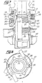
- FIGS. 7 and 8 show two connection devices, one composed of the multiple threaded pieces 24 and 25, the other of the multiple threaded pieces 26 and 27.
- the female connection piece 26 can be made integral with a well head receptacle 28 or be incorporated into it by any known means.
- the male part 27 surrounds the well head 25 and its lower end serves, after tightening and locking, as a stop for a flange 29 of the well head 25.
- the upper part of the high pressure wellhead 25 comprises a multiple thread with 8 threads for example and is surrounded by the connecting piece 24.
- This piece belongs to a set 30 and has a groove surrounding its multiple threads surrounding the flange 31 of the same assembly 30 serving as a hydraulic connector.
- the assembly 30 also includes the flanges 32, 33, 34 and 35 used for fixing vertical axes, such as 36, for example supporting the cylinder bodies 37.
- the rods 38 of these cylinders have their ends fixed to vertical axes, such as 39 adjoining the flanges 40 of the connection piece with multiple threads 24. It is therefore sufficient to order the jacks 37 so that the rods 38 cause the connection piece 24 to rotate by one eighth of tower.
- connection device 24, 25 is held in tightness by the blocking produced by the control of the jacks 37. It is thus easy to repeat the connection and disconnection of the well head.
- the tube 60 has for this purpose on its external upper part six threads, for example on which tighten six threads carried on the connecting piece 70.
- This connecting piece like the piece 24 of the previous example already belongs to a set which is this time that of the lower part of the tube 80.
- An extension 49 of the tube 60 without thread allows after tightening of the connecting piece 70 to be applied laterally against a sealing ring 50 disposed in a groove of a lower extension of the flange 42 of the tube 80 supporting the piece of connection 70.
- the tubes 60 and 80 respectively have flanges 43 and 44 used for fixing the sleeves such as 45 for the passage of the guide lines 46.
- connection device described can be applied to any rapid connection of tubular elements, the prestressing of the threads obtained at the end of tightening of the elements not being affected by the possible blocking connection when the latter is made necessary either during use involving a torque in the opposite direction to that of the tightening torque, or during use requiring high security against loosening.
- connection between the connected parts by means of threads undergoing prestress at the end of tightening after a rotation of a fraction of a turn is suitable for the use of the connected parts. It follows that if it is necessary to separate and then reconnect tubes such as 60 and 80 by means of the connecting piece 70 can be used as connecting means between the tube 60 and the connector 70 the device shown figure 11.
- the lever 55 secured to the yoke 51 rotating in its support 90 mounted on the connector 70 is located horizontally and on the side opposite the cleat 54 secured to the flange 43 of the tube 60.
- a lever 52 rotating freely around the axis 56 carried by the yoke 51 is retained by the edge 53 of an extra thickness thereof. Under these conditions, the lever 52 is horizontal and opposite the lever 55.
- the invention makes it possible, by a clever combination of the dimensions of the diameter of the connector, the thread pitch and the taper of the nominal surfaces, to preserve the self-locking characteristics of the connections by conventional thread and therefore to create prestresses. while retaining the advantages of a bayonet coupling.
- the provisions of the invention also apply to the connection of solid rods in multiple applications and in particular to the constitution of anchoring piers for oil platforms.
Landscapes
- Engineering & Computer Science (AREA)
- Life Sciences & Earth Sciences (AREA)
- Geology (AREA)
- Mining & Mineral Resources (AREA)
- Mechanical Engineering (AREA)
- Physics & Mathematics (AREA)
- Environmental & Geological Engineering (AREA)
- Fluid Mechanics (AREA)
- General Life Sciences & Earth Sciences (AREA)
- Geochemistry & Mineralogy (AREA)
- Earth Drilling (AREA)
- Non-Disconnectible Joints And Screw-Threaded Joints (AREA)
Claims (10)
Priority Applications (1)
| Application Number | Priority Date | Filing Date | Title |
|---|---|---|---|
| AT83401399T ATE23602T1 (de) | 1982-07-07 | 1983-07-07 | Verbindungsvorrichtung fuer futter- oder steigrohre, insbesondere zum unterwasserbohren. |
Applications Claiming Priority (4)
| Application Number | Priority Date | Filing Date | Title |
|---|---|---|---|
| FR8211939A FR2529991B1 (de) | 1982-07-07 | 1982-07-07 | |
| FR8211939 | 1982-07-07 | ||
| FR8213381 | 1982-07-20 | ||
| FR8213381 | 1982-07-30 |
Publications (2)
| Publication Number | Publication Date |
|---|---|
| EP0100259A1 EP0100259A1 (de) | 1984-02-08 |
| EP0100259B1 true EP0100259B1 (de) | 1986-11-12 |
Family
ID=26222981
Family Applications (1)
| Application Number | Title | Priority Date | Filing Date |
|---|---|---|---|
| EP83401399A Expired EP0100259B1 (de) | 1982-07-07 | 1983-07-07 | Verbindungsvorrichtung für Futter- oder Steigrohre, insbesondere zum Unterwasserbohren |
Country Status (11)
| Country | Link |
|---|---|
| EP (1) | EP0100259B1 (de) |
| JP (1) | JPS5923180A (de) |
| KR (1) | KR840005516A (de) |
| AU (1) | AU560764B2 (de) |
| BR (1) | BR8303617A (de) |
| CA (1) | CA1207657A (de) |
| DE (1) | DE3367649D1 (de) |
| DK (1) | DK312983A (de) |
| ES (1) | ES8403594A1 (de) |
| NO (1) | NO161987C (de) |
| OA (1) | OA07484A (de) |
Cited By (2)
| Publication number | Priority date | Publication date | Assignee | Title |
|---|---|---|---|---|
| RU2757481C1 (ru) * | 2020-10-13 | 2021-10-18 | Федеральное государственное бюджетное образовательное учреждение высшего образования "Тюменский индустриальный университет" (ТИУ) | Разъединитель бурильной колонны |
| RU2807169C1 (ru) * | 2023-03-10 | 2023-11-10 | Федеральное государственное бюджетное образовательное учреждение высшего образования "Тюменский индустриальный университет" (ТИУ) | Разъединитель эксплуатационной колонны |
Families Citing this family (11)
| Publication number | Priority date | Publication date | Assignee | Title |
|---|---|---|---|---|
| US4610467A (en) * | 1981-07-06 | 1986-09-09 | Dril-Quip, Inc. | Connector |
| JPH0695824B2 (ja) * | 1985-01-14 | 1994-11-24 | 株式会社日立製作所 | 磁石式直流機の固定子 |
| JPS61126779U (de) * | 1985-01-24 | 1986-08-08 | ||
| DE3513347C1 (en) * | 1985-04-13 | 1987-01-02 | Karl Burgsmueller | Conical, multi-start threaded connection for fastening parts of a deep-drilling tool |
| DE3673875D1 (de) * | 1985-06-06 | 1990-10-11 | Nippon Denso Co | Magnetlaeufer. |
| US4757593A (en) * | 1986-03-20 | 1988-07-19 | Vetco Gray Inc | Method of locking a connector |
| US4846508A (en) * | 1987-12-16 | 1989-07-11 | Vetco Gray Inc. | Tubular connector system |
| GB2220716B (en) * | 1988-06-17 | 1992-06-03 | Vetco Gray U K Limited | An indicator system for threaded connections |
| FR2749369B1 (fr) * | 1996-06-03 | 1998-09-04 | Domine Sa | Dispositif de connexion rapide de tubes |
| CN102733763B (zh) * | 2012-06-16 | 2014-10-08 | 无锡西姆莱斯石油专用管制造有限公司 | 高抗挤特殊螺纹套管连接接头 |
| CN120312155B (zh) * | 2025-05-07 | 2026-01-30 | 江苏亿德隆石油机械有限公司 | 一种采油井口套管头 |
Citations (1)
| Publication number | Priority date | Publication date | Assignee | Title |
|---|---|---|---|---|
| US2885225A (en) * | 1955-02-17 | 1959-05-05 | Drilco Oil Tools Inc | Drill pipe coupling having particular thread formations |
Family Cites Families (12)
| Publication number | Priority date | Publication date | Assignee | Title |
|---|---|---|---|---|
| DE628915C (de) * | 1931-12-23 | 1936-04-18 | Spang Chalfant & Co Inc | Gewindeverbindung fuer Rohre |
| DE701558C (de) * | 1935-02-19 | 1941-01-18 | Chalfant And Co Inc | Schraubverbindung der Futterrohre fuer Tiefbohrloecher |
| US2215770A (en) * | 1939-09-29 | 1940-09-24 | William F Sheffield | Drilling shaft coupling |
| US2587544A (en) * | 1948-06-01 | 1952-02-26 | United States Steel Corp | Threaded joint capable of being quickly made and broken |
| GB804798A (en) * | 1954-05-11 | 1958-11-26 | Joy Mfg Co | Screwing-up and unscrewing mechanism for an oil well drill pipe |
| US3086796A (en) * | 1958-11-13 | 1963-04-23 | Fmc Corp | Pipe coupling with wedging locking means |
| GB897572A (en) * | 1959-05-20 | 1962-05-30 | Dowty Rotol Ltd | Improvements relating to a unit for tightening and loosening a screwed pipe joint inearth boring equipment |
| US3129963A (en) * | 1960-06-30 | 1964-04-21 | Robbins Machine & Mfg Co | Low release torque threaded joint |
| BE633562A (de) * | 1962-06-26 | |||
| CH479017A (de) * | 1968-12-09 | 1969-09-30 | Naamanka Armas | Anordnung zum Anschliessen von zwei Schläuchen oder Rohren aneinander |
| US4043575A (en) * | 1975-11-03 | 1977-08-23 | The Rucker Company | Riser connector |
| GB2064041B (en) * | 1979-11-19 | 1983-07-27 | Hunting Oilfield Services Ltd | Pipe connectors |
-
1983
- 1983-07-05 NO NO832449A patent/NO161987C/no not_active IP Right Cessation
- 1983-07-05 ES ES523882A patent/ES8403594A1/es not_active Expired
- 1983-07-06 BR BR8303617A patent/BR8303617A/pt not_active IP Right Cessation
- 1983-07-06 CA CA000431954A patent/CA1207657A/en not_active Expired
- 1983-07-06 AU AU16614/83A patent/AU560764B2/en not_active Ceased
- 1983-07-06 DK DK312983A patent/DK312983A/da not_active Application Discontinuation
- 1983-07-06 OA OA58051A patent/OA07484A/xx unknown
- 1983-07-07 JP JP58122442A patent/JPS5923180A/ja active Pending
- 1983-07-07 DE DE8383401399T patent/DE3367649D1/de not_active Expired
- 1983-07-07 KR KR1019830003104A patent/KR840005516A/ko not_active Withdrawn
- 1983-07-07 EP EP83401399A patent/EP0100259B1/de not_active Expired
Patent Citations (1)
| Publication number | Priority date | Publication date | Assignee | Title |
|---|---|---|---|---|
| US2885225A (en) * | 1955-02-17 | 1959-05-05 | Drilco Oil Tools Inc | Drill pipe coupling having particular thread formations |
Cited By (2)
| Publication number | Priority date | Publication date | Assignee | Title |
|---|---|---|---|---|
| RU2757481C1 (ru) * | 2020-10-13 | 2021-10-18 | Федеральное государственное бюджетное образовательное учреждение высшего образования "Тюменский индустриальный университет" (ТИУ) | Разъединитель бурильной колонны |
| RU2807169C1 (ru) * | 2023-03-10 | 2023-11-10 | Федеральное государственное бюджетное образовательное учреждение высшего образования "Тюменский индустриальный университет" (ТИУ) | Разъединитель эксплуатационной колонны |
Also Published As
| Publication number | Publication date |
|---|---|
| NO161987C (no) | 1989-10-18 |
| EP0100259A1 (de) | 1984-02-08 |
| JPS5923180A (ja) | 1984-02-06 |
| ES523882A0 (es) | 1984-04-01 |
| ES8403594A1 (es) | 1984-04-01 |
| NO161987B (no) | 1989-07-10 |
| BR8303617A (pt) | 1984-02-14 |
| OA07484A (fr) | 1984-12-31 |
| DK312983A (da) | 1984-01-08 |
| DE3367649D1 (en) | 1987-01-02 |
| KR840005516A (ko) | 1984-11-14 |
| CA1207657A (en) | 1986-07-15 |
| NO832449L (no) | 1984-01-09 |
| AU1661483A (en) | 1984-02-09 |
| AU560764B2 (en) | 1987-04-16 |
| DK312983D0 (da) | 1983-07-06 |
Similar Documents
| Publication | Publication Date | Title |
|---|---|---|
| EP0254630B1 (de) | Verbindungsvorrichtung zur schnellen Demontage unter Last | |
| CA2388688C (fr) | Joint tubulaire filete etanche a la pression exterieure | |
| EP0867596B1 (de) | Gewindeverbinder für Rohre | |
| EP1110019B1 (de) | Metallrohrschraubverbindung mit hohem drehmoment | |
| EP0100259B1 (de) | Verbindungsvorrichtung für Futter- oder Steigrohre, insbesondere zum Unterwasserbohren | |
| EP0565445B1 (de) | Vorrichtung zum Verlegen eines mit einem Krümmungsbegrenzer versehenen flexiblen Rohrstrangs | |
| CA2466791C (fr) | Joint filete tubulaire superieur comprenant au moins un element filete avec levre d'extremite | |
| EP0027406B1 (de) | Mit einem Kettenring versehene Rohrverbindung | |
| FR2493888A1 (fr) | Raccord pour tubes de pieux a enfoncer | |
| FR2507281A1 (fr) | Appareil et procede pour raccorder des elements tubulaires | |
| EP0089253B1 (de) | Hochdruckdichtende Rohrkupplung aus Stahl mit geringer Heisslaufneigung | |
| FR2526079A2 (fr) | Ensemble a raccord | |
| FR2567616A1 (fr) | Ensemble a raccord, appareil de raccordement, joint de tubes et procede de realisation d'un raccord visse entre deux elements longitudinaux | |
| FR2807095A1 (fr) | Element filete tubulaire delarde pour joint filete tubulaire resistant a la fatigue et joint filete tubulaire resultant | |
| FR3029593A1 (fr) | Composant tubulaire a butee helicoidale | |
| WO1986002123A1 (fr) | Procede et dispositif pour effectuer le vissage d'un joint filete pour tube muni d'une butee | |
| FR3046210A1 (fr) | Embout de connexion d'une ligne flexible, ligne flexible et procede de montage associes | |
| FR2529991A1 (de) | ||
| FR2953271A1 (fr) | Ensemble pour la realisation d'un joint filete, procede de vissage et de devissage d'un tel joint et utilisation d'un tel joint dans une colonne montante sous-marine | |
| FR2526517A2 (fr) | Connecteur a anneau tournant, en particulier pour colonne montante utilisee dans l'exploration ou la production petroliere en mer | |
| FR2464426A2 (fr) | Connecteur a anneau tournant, en particulier pour colonne montante utilisee dans l'exploration ou la production petroliere en mer | |
| EP0034101B1 (de) | Abnehmbare Verbindung, insbesondere zum Verbinden zweier Röhren oder Leitungen | |
| FR2954453A1 (fr) | Ensemble pour la realisation d'un joint filete, procede de vissage et de devissage d'un tel joint et utilisation d'un tel joint dans une colonne montante sous-marine | |
| EP1038139B1 (de) | Vorrichtung zum dichten verbinden von rohren für den transport von flüssigkeiten | |
| EP4479620B1 (de) | Gewindeverbindung mit abschraubsicherungsvorrichtung |
Legal Events
| Date | Code | Title | Description |
|---|---|---|---|
| PUAI | Public reference made under article 153(3) epc to a published international application that has entered the european phase |
Free format text: ORIGINAL CODE: 0009012 |
|
| AK | Designated contracting states |
Designated state(s): AT BE CH DE FR GB IT LI LU NL SE |
|
| 17P | Request for examination filed |
Effective date: 19840719 |
|
| RAP1 | Party data changed (applicant data changed or rights of an application transferred) |
Owner name: VETCO OFFSHORE LIMITED |
|
| GRAA | (expected) grant |
Free format text: ORIGINAL CODE: 0009210 |
|
| RAP1 | Party data changed (applicant data changed or rights of an application transferred) |
Owner name: VETCO OFFSHORE INDUSTRIES, INC. |
|
| AK | Designated contracting states |
Kind code of ref document: B1 Designated state(s): AT BE CH DE FR GB IT LI LU NL SE |
|
| PG25 | Lapsed in a contracting state [announced via postgrant information from national office to epo] |
Ref country code: IT Free format text: LAPSE BECAUSE OF FAILURE TO SUBMIT A TRANSLATION OF THE DESCRIPTION OR TO PAY THE FEE WITHIN THE PRESCRIBED TIME-LIMIT;WARNING: LAPSES OF ITALIAN PATENTS WITH EFFECTIVE DATE BEFORE 2007 MAY HAVE OCCURRED AT ANY TIME BEFORE 2007. THE CORRECT EFFECTIVE DATE MAY BE DIFFERENT FROM THE ONE RECORDED. Effective date: 19861112 Ref country code: AT Effective date: 19861112 |
|
| REF | Corresponds to: |
Ref document number: 23602 Country of ref document: AT Date of ref document: 19861115 Kind code of ref document: T |
|
| PG25 | Lapsed in a contracting state [announced via postgrant information from national office to epo] |
Ref country code: SE Effective date: 19861130 |
|
| REF | Corresponds to: |
Ref document number: 3367649 Country of ref document: DE Date of ref document: 19870102 |
|
| PG25 | Lapsed in a contracting state [announced via postgrant information from national office to epo] |
Ref country code: LU Free format text: LAPSE BECAUSE OF NON-PAYMENT OF DUE FEES Effective date: 19870731 Ref country code: LI Effective date: 19870731 Ref country code: CH Effective date: 19870731 |
|
| PGFP | Annual fee paid to national office [announced via postgrant information from national office to epo] |
Ref country code: NL Payment date: 19870731 Year of fee payment: 5 |
|
| PLBE | No opposition filed within time limit |
Free format text: ORIGINAL CODE: 0009261 |
|
| STAA | Information on the status of an ep patent application or granted ep patent |
Free format text: STATUS: NO OPPOSITION FILED WITHIN TIME LIMIT |
|
| 26N | No opposition filed | ||
| BERE | Be: lapsed |
Owner name: VETCO OFFSHORE INDUSTRIES INC. Effective date: 19870731 |
|
| REG | Reference to a national code |
Ref country code: CH Ref legal event code: PL |
|
| PG25 | Lapsed in a contracting state [announced via postgrant information from national office to epo] |
Ref country code: DE Effective date: 19880401 |
|
| PG25 | Lapsed in a contracting state [announced via postgrant information from national office to epo] |
Ref country code: BE Effective date: 19890731 |
|
| PG25 | Lapsed in a contracting state [announced via postgrant information from national office to epo] |
Ref country code: NL Effective date: 19900201 |
|
| NLV4 | Nl: lapsed or anulled due to non-payment of the annual fee | ||
| PGFP | Annual fee paid to national office [announced via postgrant information from national office to epo] |
Ref country code: FR Payment date: 20010625 Year of fee payment: 19 |
|
| REG | Reference to a national code |
Ref country code: GB Ref legal event code: IF02 |
|
| PGFP | Annual fee paid to national office [announced via postgrant information from national office to epo] |
Ref country code: GB Payment date: 20020723 Year of fee payment: 20 |
|
| PG25 | Lapsed in a contracting state [announced via postgrant information from national office to epo] |
Ref country code: FR Free format text: LAPSE BECAUSE OF NON-PAYMENT OF DUE FEES Effective date: 20030331 |
|
| REG | Reference to a national code |
Ref country code: FR Ref legal event code: ST |
|
| PG25 | Lapsed in a contracting state [announced via postgrant information from national office to epo] |
Ref country code: GB Free format text: LAPSE BECAUSE OF EXPIRATION OF PROTECTION Effective date: 20030706 |
|
| REG | Reference to a national code |
Ref country code: GB Ref legal event code: PE20 |