EP0100025A1 - Synchronisierungseinrichtung für Zahnradwechselgetriebe - Google Patents
Synchronisierungseinrichtung für Zahnradwechselgetriebe Download PDFInfo
- Publication number
- EP0100025A1 EP0100025A1 EP83106875A EP83106875A EP0100025A1 EP 0100025 A1 EP0100025 A1 EP 0100025A1 EP 83106875 A EP83106875 A EP 83106875A EP 83106875 A EP83106875 A EP 83106875A EP 0100025 A1 EP0100025 A1 EP 0100025A1
- Authority
- EP
- European Patent Office
- Prior art keywords
- teeth
- ring
- synchronization
- idler gear
- toothing
- Prior art date
- Legal status (The legal status is an assumption and is not a legal conclusion. Google has not performed a legal analysis and makes no representation as to the accuracy of the status listed.)
- Granted
Links
Images


Classifications
-
- F—MECHANICAL ENGINEERING; LIGHTING; HEATING; WEAPONS; BLASTING
- F16—ENGINEERING ELEMENTS AND UNITS; GENERAL MEASURES FOR PRODUCING AND MAINTAINING EFFECTIVE FUNCTIONING OF MACHINES OR INSTALLATIONS; THERMAL INSULATION IN GENERAL
- F16D—COUPLINGS FOR TRANSMITTING ROTATION; CLUTCHES; BRAKES
- F16D23/00—Details of mechanically-actuated clutches not specific for one distinct type
- F16D23/02—Arrangements for synchronisation, also for power-operated clutches
- F16D23/025—Synchro rings
-
- F—MECHANICAL ENGINEERING; LIGHTING; HEATING; WEAPONS; BLASTING
- F16—ENGINEERING ELEMENTS AND UNITS; GENERAL MEASURES FOR PRODUCING AND MAINTAINING EFFECTIVE FUNCTIONING OF MACHINES OR INSTALLATIONS; THERMAL INSULATION IN GENERAL
- F16D—COUPLINGS FOR TRANSMITTING ROTATION; CLUTCHES; BRAKES
- F16D23/00—Details of mechanically-actuated clutches not specific for one distinct type
- F16D23/02—Arrangements for synchronisation, also for power-operated clutches
- F16D23/04—Arrangements for synchronisation, also for power-operated clutches with an additional friction clutch
- F16D23/06—Arrangements for synchronisation, also for power-operated clutches with an additional friction clutch and a blocking mechanism preventing the engagement of the main clutch prior to synchronisation
- F16D2023/0656—Details of the tooth structure; Arrangements of teeth
- F16D2023/0668—Details relating to tooth end or tip geometry
-
- F—MECHANICAL ENGINEERING; LIGHTING; HEATING; WEAPONS; BLASTING
- F16—ENGINEERING ELEMENTS AND UNITS; GENERAL MEASURES FOR PRODUCING AND MAINTAINING EFFECTIVE FUNCTIONING OF MACHINES OR INSTALLATIONS; THERMAL INSULATION IN GENERAL
- F16D—COUPLINGS FOR TRANSMITTING ROTATION; CLUTCHES; BRAKES
- F16D23/00—Details of mechanically-actuated clutches not specific for one distinct type
- F16D23/02—Arrangements for synchronisation, also for power-operated clutches
- F16D23/04—Arrangements for synchronisation, also for power-operated clutches with an additional friction clutch
- F16D23/06—Arrangements for synchronisation, also for power-operated clutches with an additional friction clutch and a blocking mechanism preventing the engagement of the main clutch prior to synchronisation
- F16D2023/0656—Details of the tooth structure; Arrangements of teeth
- F16D2023/0675—Details relating to special undercut geometry
Definitions
- the subject of the present invention is a synchronization device intended for a dog clutch gearbox of the type making it possible to prohibit dog clutching as long as the respective rotational speeds of the parts to be clutched are not equal.
- Such synchronization devices can be used in particular for the gearboxes of motor vehicles.
- Known devices of this type generally include a portable player mounted on a hub secured to a rotary shaft.
- a synchronization ring has a conical surface which can cooperate with another conical surface of one of the parts to be clutched so as to constitute a small clutch kept in engagement by means of the gear change control for the time necessary to obtain the equalization of the angular velocities of the members to be clutched.
- the player is the first of these organs, the second being a idler gear mounted free in rotation on the shaft carrying the hub of the player.
- the synchronization ring is provided with an external conical surface which is adapted to cooperate with an internal conical surface of the player.
- the ring comprises a certain number of lugs, the sides of which cooperate with corresponding notches made in the toothing of the idler pinion in order to act as indexing means in rotation of the ring relative to the pinion before and during the synchronization by equalization of the relative rotational speeds on the one hand of the ring driven with the player by its conical surface and on the other hand, of the idler gear.
- the synchronization ring is recalled by an elastic ring in a circle position, one of the ends of which is fixed to the idler gear. It is found in practice that such a device has certain drawbacks.
- the synchronization ring is difficult to produce and requires tools important given its complex structure and in particular the existence of the indexing tabs practiced inside the ring.
- the precise production of the notches serving as stops for these indexing lugs in the idler gear is difficult as well as obtaining a suitable surface state in particular at the junction between the notches and the teeth of clutching of the idler gear.
- the elastic ring is fixed at one of its ends and bears only on the indexing lugs of the ring results in poor centering of the ring relative to the cone of the player and to the idler gear.
- the very structure of the synchronization ring means that the device as a whole has a large axial size causing a significant displacement of the player relative to the pinion before engagement of the dog clutch which can present risks of desynchronization. .
- the object of the present invention is therefore to provide a synchronization device which eliminates these drawbacks and in which the indexing in rotation at the time of synchronization is carried out directly by the clutch gear teeth of the idler gear.
- the subject of the invention is also a synchronization device in which a synchronization ring with a conical surface is centered relative to the idler gear by means of the latter's interconnecting teeth so that the indexing in rotation before the start of the synchronization operation is done by cooperation of two parts perfectly centered with respect to each other, namely the synchronization ring and the idler gear.
- Another object of the invention is to improve the circumferential distribution of the retaining and restoring force exerted by the elastic ring cooperating with the synchronization ring.
- the object of the invention is to use all the teeth inputs of the idler sprocket dogs to constitute arming ramps ensuring indexing in rotation by the cooperation of multiple and precise surfaces immediately before synchronization.
- the synchronization device for dog gearbox makes it possible to prohibit dog clutching as long as there is no equality of the respective rotational speeds of a idler gear mounted free to rotate on a shaft and a player mounted on a hub integral with said shaft, the player rotating with the hub and being able to slide axially relative to the hub.
- the synchronization device according to the invention comprises a synchronization ring provided with an external conical surface adapted to cooperate with an internal conical surface of the player.
- the synchronization ring is also provided with rotation indexing means adapted to cooperate with stop means integral with the idler gear.
- the device also includes an elastic return ring for the synchronization ring.
- the synchronization ring comprises two parts which will be called in the following description, front part and rear part according to the direction of movement of the synchronization ring towards the idler gear during a gear engagement movement. of speed.
- the synchronization ring comprises a first toothing capable of meshing with an external dog clutch teeth formed over the entire periphery of a portion of the idler gear.
- All the teeth of the two aforementioned teeth intended to cooperate with each other have tooth inlets provided with arming ramps inclined substantially in the form of a wedge adapted to come into contact with each other so as to ensure indexing in rotation, that is to say a precise angular position of the synchronization ring relative to the idler gear.
- the synchronization ring also comprises over the entire internal periphery of its front part, a plurality of notches whose sides are offset in the peripheral direction relative to the teeth inlets of the first toothing of the rear part.
- This offset of a predetermined value, is chosen so that the aforementioned arming ramps are in contact when the sides of said notches are in contact with the sides of the idler teeth of the idler gear.
- the notches in the front part of the synchronization ring are preferably formed by the crossbeams of a second toothing formed over the entire internal periphery of the front part of the synchronization ring.
- the pitch of this second toothing is preferably double that of the first toothing which in practice makes it possible to ensure adequate covering of the faces in contact with the aforementioned arming ramps.
- One tooth in two of the idler teeth of the idler gear is cut substantially halfway along a cylindrical centering surface concentric with the axis of the synchronization device. These cylindrical surfaces cooperate with the cylindrical surface also cut substantially at mid-height of the teeth of the second toothing of the ring. Under these conditions, the exact centering of the ring relative to the idler gear is ensured by every other tooth of the clutch gear teeth of the idler gear.
- An elastic retaining ring is preferably mounted so as to be trapped in an internal groove separating the front and rear parts of the synchronization ring. In the rest or neutral position, before synchronization, the elastic ring is housed in an external groove in the idler gear. In this way, during the prior rotary indexing operation, the elastic retaining ring is capable of exerting a force against the engagement movement of the synchronization ring on the idler gear.
- the return of the elastic ring is preferably done by means of an axial return slope made on one tooth out of two of the idler gear teeth.
- the elastic ring therefore moves on multiple and precise conical surfaces which are distributed around the circumference of the idler gear teeth also ensuring in this way a better distribution of the retaining force during arming and indexing in rotation and during the return of the synchronization ring .
- the player conventionally comprises an internal toothing which meshes with an external toothing of the hub on which it is slidably mounted.
- the toothing of the player preferably has for each entry a setback limiting the active part of the teeth in contact with those of the idler gear.
- the sides of the clutch dog teeth and idler gear preferably have on part of their height conical hooking faces machined in dovetail making it possible to avoid letting go of the clutching under torque.
- the synchronization device is mounted on a shaft 1 forming part of a gearbox and the peripheral surface of which is provided with splines 2.
- On the shaft 1 are mounted two idler gears 3 and 4 free to rotate relative to the shaft 1.
- a splined hub 5 is mounted on the shaft 1 so as to be integral in rotation with the latter by means of the splines 2.
- the hub 5 is held axially by two stop rings 6 positioned in grooves 7 of the shaft 1.
- the idler gears 3 and 4 are mounted on either side of the hub 5, the assembly being held axially between a shoulder 8 of the shaft 1 and a stop ring 9.
- a walkman 10 is mounted on the periphery of the hub 5 so as to be driven in rotation with the latter and to slide axially relative to the hub.
- the axial sliding of the player 10 relative to the hub 5 is carried out under the action of a control member, not shown, which comes to bear in an external peripheral groove 11 of the player.
- the synchronization device is double so as to allow synchronization of each of the idler gears 3 and 4.
- the player has for this purpose two internal conical surfaces 12 formed on two annular protrusions 13 of the player 10. These internal conical surfaces 12 cooperate with corresponding external conical surfaces 14 of two synchronization rings 15 of identical structure.
- Each of the two pinions 3 and 4 has an external toothing 16, 17 intended to cooperate respectively with a toothed wheel forming part of the gearbox not shown in the figures, so as to achieve the engagement of a determined speed ratio .
- the diameter of the teeth 16 of the pinion 3 is larger than that of the teeth 17 of the pinion 4 thus making it possible to define two different speed ratios.
- Each pinion 3, 4 comprises, on the side of the central hub 5 a portion 18 projecting axially having an external diameter substantially equal to that of the hub 5 and provided externally with a dog clutch teeth 19.
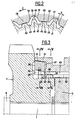
- the synchronization ring 15 comprises a rear part 20 and a front part 21, the front part 21 being identified in the direction of movement of the synchronization ring 15 towards the idler gear 3 when engaging a gear speed by moving the player 10 from the position illustrated in FIG. 1 to the position illustrated in fig. 3.
- the synchronization ring has a first toothing constituted by teeth 22 and between 23 (fig. 6).
- Each tooth 22 has a tooth inlet provided with inclined arming ramps 24 and 25 so as to substantially define a wedge shape.
- the internal bore of all of the crossbeams 23 has a conical surface 26.
- the synchronization ring 15 comprises a plurality of notches formed by the crossbeams 27 of a second toothing whose teeth 28 are cut substantially at mid-height thus forming a cylindrical surface 29 (fig. 2 and 6).
- the internal surface of the entredents 27 is a conical surface 30 of the same inclination as the conical surface-26.
- the sides 31 and 32 of the teeth 27 are offset in the peripheral direction with respect to the sides 33 and 34 of the teeth 23.
- the first toothing is therefore also offset with respect to the entries of teeth 24, 25 of teeth 22.
- the pitch of the second toothing 27, 28 is double that of the first toothing 22, 23.
- a different ratio could be adopted.
- An internal groove 35 (FIG. 1) separates the rear 20 and front 21 parts of the synchronization ring 15, said groove 35 being formed radially in the ring 15 and having a width adapted to receive an elastic retaining ring 36 consisting for example by a metal ring of semi-circular shape cut in one place so as to ensure a suitable elasticity by deformation.
- the synchronization ring 15 has a section of generally simple shape, substantially trapezoidal. Indeed, it has two planar radial end faces 37 and 38, a conical outer face 14 and an internal bore which is defined by the two teeth 27, 28 and 22, 23. On this internal bore only the heads of the teeth 22 therefore make protruding inward.
- the synchronization ring 15 constitutes a relatively simple mechanical part to be machined having substantially the same stiffness in the radial direction and in the axial direction and whose center of gravity is substantially median.
- the two teeth 27, 28 and 22, 23 cut in an involute to a circle are easy to produce with the necessary machining precision.
- the external conical surface 14 of the synchronization ring 15 has a slightly projecting thread 39 as well as grooves 40 also distributed over the periphery so as to facilitate the evacuation of the oil (fig. 6).
- the external dog clutch teeth 19 arranged on the portion 18 of the idler gear 3 comprises teeth 41 alternating with teeth 42 separated by intermedents 43 (FIG. 2).
- Each of the teeth 41 has a conical outer surface defining a slope 44.
- Each of the teeth 42 is cut substantially at mid-height thus defining a cylindrical centering surface 45 concentric with the axis of the synchronization device and, cooperating with the cylindrical surface 29 also cut halfway up the teeth 28 of the synchronization ring 15.
- each tooth 28 of the teeth of the part before 21 of the synchronization ring 15 is supported by its bore on the external cylindrical surface 45 of a tooth 42 on two of the interconnection teeth 19 of the pinion fo ⁇ 3.
- the synchronization ring 15 is therefore perfectly centered relative to the idler gear 3 by a multitude of cylindrical contact portions defined on the corresponding teeth of the synchronization ring 15 and the dog clutch 19.
- the teeth 41 also have an external groove 46 visible in particular in FIG. 3 adapted to accommodate in the rest position corresponding to neutral, the elastic ring 36 as can be seen in FIG. 1.
- the elastic ring 36 still trapped in the internal groove 35 of the synchronization ring 15 exerts a retaining force thanks to the existence of the groove 46, against the engagement movement of the 'ring 15.
- the elastic ring 36 and the external groove 46 therefore play the role of abutment means for the synchronization ring 15 during the operating phase preliminary to synchronization.
- the axial return slopes 44 allowing the return movement of the elastic ring 36 and the ring 15 in the direction of the rest position illustrated in FIG. 1.
- the dog toothing 19 of the idler gear 3 has entries of teeth with inclined faces 50. These inclined faces 50 visible in particular in FIGS. 7 and 8 constitute arming ramps capable of coming into contact with the inputs of teeth of corresponding inclined shape 24 or 25 of teeth 22 as can be seen in particular in FIG. 7.
- the walkman 10 has an internal dog clutch teeth comprising teeth 47 (FIG. 5), each entry having a recess 48 limiting the active part of the teeth 47.
- the teeth 47 On each side of the walkman 10, the teeth 47 have tooth entries 49 ( Fig. 1 and 3) provided with wedge-shaped inclined faces.
- Retention in position of the selected gear ratio is achieved by a conical attachment constituted by faces machined in dovetail 51 on the lower portions of the teeth 41 and 42 of the idler gear 3 as well as corresponding faces also machined in dovetail 52 on the teeth 47 of the player. _ ⁇
- the interconnection teeth formed by the teeth 47 of the player 10 further cooperates with a corresponding toothing formed at the periphery of the hub 5 and whose teeth 53 are visible in particular in FIG. 1.
- All of the above-mentioned teeth are preferably cut in an involute.
- the operation of the synchronization device according to the invention is as follows.
- the player 10 is first of all subjected to a force tending to move it, for example to the left of FIG. 1 when it is desired to engage the gear ratio corresponding to the idler gear 3.
- the internal cone 12 of the player 10 therefore exerts a thrust on the external conical surface 14 of the synchronization ring 15.
- the ring 15, centered as it has been indicated above with respect to the idler gear 3 by the cooperation of the corresponding cylindrical surfaces 29 and 45, is retained by the elastic ring 36 cooperating with the groove 46.
- the axial movement of the sliding gear 10 is therefore stopped as long as the idler gear 3 and the player 10 driven by the hub 5 have a speed relative to each other.
- the synchronization ring 15 undergoes a rotation, for example in the direction of the arrow G in FIG. 2 until the faces 31 of the intermedents 27 come into contact with the flanks of the teeth 41 of the dog clutch teeth 19.
- the exact value of this movement is referenced X in FIG. 2 and it can be precisely defined when machining the different teeth.
- the position after rotation of the X value is shown in fig. 6. In this position, the faces 25 of the teeth 22 of the synchronization ring 15 are in contact with the arming ramps 50 of the teeth inlets of the teeth 41 and 42 of the dog clutch teeth 19 of the idler gear 3.
- the precise position or indexing in rotation of the synchronization ring 15 relative to the idler gear 3, is obtained by the notches of the teeth of the part before 21 of the synchronization ring 15 which cooperate with the teeth of the dog clutch teeth 19.
- This indexing therefore takes place on a multitude of precisely machined surfaces.
- the value of the overlap that is to say the contact surface between the arming ramp 50 and the tooth inlet 25 is thus precisely defined by the indexing in rotation.
- the elastic ring 36 expands as it moves on the axial slopes 44 of the teeth 41 remaining trapped in the internal groove 35 of the ring 15.
- the teeth 47 of the wand 10 can penetrate into the teeth of the dog teeth 19 of the idler gear 3 thus ensuring the interconnection as illustrated in FIG. 3. Retention of the gear ratio is ensured, as seen in particular in FIG. 8, by the faces machined in dovetail 51 and 52.
- the synchronization device therefore uses the dog clutch teeth 19 of the idler gears as a means of indexing and arming prior to synchronization.
- Return ramps 44 are formed on the tops of the teeth 41 of the dog clutch 19 thus ensuring the return to neutral of the synchronization ring 15.
- the synchronization ring 15 is perfectly centered throughout its movement relative to the teeth dog clutch 19 of the idler gear 3.
- the axial position of the synchronization ring 15 is precisely defined by means of the groove 46 which allows the elastic ring 36 to be accommodated.
- the arming ramps 50 are formed by all of the teeth inlets of the dog clutch teeth 19 of the idler gear thus making it possible to obtain a small covering surface on multiple faces and machined with precision.
- the structure of the device of the invention makes it possible to - significantly reduce the movement of the player before dog clutching, thereby significantly reducing the risks of desynchronization.
Landscapes
- Engineering & Computer Science (AREA)
- General Engineering & Computer Science (AREA)
- Mechanical Engineering (AREA)
- Mechanical Operated Clutches (AREA)
Applications Claiming Priority (2)
| Application Number | Priority Date | Filing Date | Title |
|---|---|---|---|
| FR8213123 | 1982-07-27 | ||
| FR8213123A FR2531172B1 (fr) | 1982-07-27 | 1982-07-27 | Dispositif de synchronisation pour boite de vitesses a crabots |
Publications (2)
| Publication Number | Publication Date |
|---|---|
| EP0100025A1 true EP0100025A1 (de) | 1984-02-08 |
| EP0100025B1 EP0100025B1 (de) | 1988-08-31 |
Family
ID=9276373
Family Applications (1)
| Application Number | Title | Priority Date | Filing Date |
|---|---|---|---|
| EP19830106875 Expired EP0100025B1 (de) | 1982-07-27 | 1983-07-13 | Synchronisierungseinrichtung für Zahnradwechselgetriebe |
Country Status (6)
| Country | Link |
|---|---|
| EP (1) | EP0100025B1 (de) |
| AR (1) | AR230685A1 (de) |
| DE (1) | DE3377878D1 (de) |
| ES (1) | ES524431A0 (de) |
| FR (1) | FR2531172B1 (de) |
| PT (1) | PT77106B (de) |
Cited By (11)
| Publication number | Priority date | Publication date | Assignee | Title |
|---|---|---|---|---|
| EP0241640A1 (de) * | 1986-04-16 | 1987-10-21 | Dr.Ing.h.c. F. Porsche Aktiengesellschaft | Sperrsynchronisiereinrichtung für ein Zahnräderwechselgetriebe eines Kraftfahrzeugs |
| EP0272103A2 (de) * | 1986-12-16 | 1988-06-22 | Toyota Jidosha Kabushiki Kaisha | Synchronisiermechanismus für Zahnradgetriebe |
| EP0272134A2 (de) * | 1986-12-18 | 1988-06-22 | Toyota Jidosha Kabushiki Kaisha | Synchronisiermechanismus für Zahnradgetriebe |
| DE3728904C1 (en) * | 1987-08-29 | 1988-07-28 | Daimler Benz Ag | Ramp-shaped female cone of a clutch ring as an abutment for an annular spring supporting a synchronising ring in a selector clutch, especially one in a change-speed gearbox |
| DE3701536A1 (de) * | 1987-01-21 | 1988-08-04 | Ford Werke Ag | Synchronisiereinrichtung fuer wechselgetriebe, insbesondere fuer kraftfahrzeuge |
| GB2203205A (en) * | 1987-03-31 | 1988-10-12 | Aisin Seiki | Power transmission synchronization |
| EP0288718A1 (de) * | 1987-04-29 | 1988-11-02 | Ford-Werke Aktiengesellschaft | Synchronisiereinrichtung für Wechselgetriebe, insbesondere für Kraftfahrzeuge |
| FR2685046A1 (fr) * | 1991-12-12 | 1993-06-18 | Daimler Benz Ag | Dispositif de synchronisation et commutation pour accoupler un pignon avec son arbre dans des boites de vitesses a engrenages. |
| DE19624699C1 (de) * | 1996-06-13 | 1998-04-23 | Korea Spicer Corp | Synchronisiervorrichtung für ein Fahrzeuggetriebe |
| FR2801354A1 (fr) * | 1999-11-22 | 2001-05-25 | Renault | Dispositif de synchronisation d'un pignon fou |
| WO2004113754A1 (en) | 2003-06-24 | 2004-12-29 | Volvo Lastvagnar Ab | Coupling element in a motor vehicle gearbox and a method to manufacture such coupling element |
Families Citing this family (3)
| Publication number | Priority date | Publication date | Assignee | Title |
|---|---|---|---|---|
| FR2729195B1 (fr) * | 1995-01-06 | 1997-03-28 | Renault | Dispositif de synchronisation notamment pour boite de vitesses |
| EP0721072A1 (de) * | 1995-01-06 | 1996-07-10 | Regie Nationale Des Usines Renault | Steuer- und Synchronisationseinrichtung eines Rückwärtsganges eines mechanisches Getriebes |
| DE102013210906A1 (de) * | 2013-06-12 | 2014-12-31 | Zf Friedrichshafen Ag | Schalteinrichtung |
Citations (12)
| Publication number | Priority date | Publication date | Assignee | Title |
|---|---|---|---|---|
| FR533129A (fr) * | 1919-11-22 | 1922-02-22 | Zahnradfabrik G M B H | Accouplement |
| US1935965A (en) * | 1931-07-16 | 1933-11-21 | Nash Motors Company | Clutch mechanism |
| US2062927A (en) * | 1932-12-19 | 1936-12-01 | Spicer Mfg Corp | Method of forming a helical gear with clutch teeth |
| GB482077A (en) * | 1937-05-10 | 1938-03-23 | Rover Co Ltd | Clutches suitable for change-speed mechanism |
| US2328205A (en) * | 1942-04-13 | 1943-08-31 | Borg Warner | Clutch |
| US2359982A (en) * | 1942-04-13 | 1944-10-10 | Borg Warner | Clutch |
| GB711201A (en) * | 1948-05-08 | 1954-06-30 | John Fowler & Co Leeds Ltd | Improvements in and relating to friction synchronised positive clutches |
| DE1030692B (de) * | 1955-03-17 | 1958-05-22 | Egon Martyrer Dr Ing | Synchronisierungseinrichtung fuer schwere, grosse Leistungen uebertragende Zahnradwechselgetriebe, insbesondere fuer Strassen- und Schienenfahrzeuge |
| US3305061A (en) * | 1964-12-16 | 1967-02-21 | Borg Warner | Axial locking clutch |
| US3424289A (en) * | 1966-02-15 | 1969-01-28 | Renault | Interlocking clutch teeth |
| FR2164389A5 (de) * | 1971-12-10 | 1973-07-27 | Newage Engineers Ltd | |
| GB2007781A (en) * | 1977-11-11 | 1979-05-23 | Johnsson T R W | Synchronising arrangement for a motor vehicle gear box |
-
1982
- 1982-07-27 FR FR8213123A patent/FR2531172B1/fr not_active Expired
-
1983
- 1983-07-13 DE DE8383106875T patent/DE3377878D1/de not_active Expired
- 1983-07-13 EP EP19830106875 patent/EP0100025B1/de not_active Expired
- 1983-07-26 PT PT7710683A patent/PT77106B/pt not_active IP Right Cessation
- 1983-07-26 ES ES524431A patent/ES524431A0/es active Granted
- 1983-07-27 AR AR29374783A patent/AR230685A1/es active
Patent Citations (12)
| Publication number | Priority date | Publication date | Assignee | Title |
|---|---|---|---|---|
| FR533129A (fr) * | 1919-11-22 | 1922-02-22 | Zahnradfabrik G M B H | Accouplement |
| US1935965A (en) * | 1931-07-16 | 1933-11-21 | Nash Motors Company | Clutch mechanism |
| US2062927A (en) * | 1932-12-19 | 1936-12-01 | Spicer Mfg Corp | Method of forming a helical gear with clutch teeth |
| GB482077A (en) * | 1937-05-10 | 1938-03-23 | Rover Co Ltd | Clutches suitable for change-speed mechanism |
| US2328205A (en) * | 1942-04-13 | 1943-08-31 | Borg Warner | Clutch |
| US2359982A (en) * | 1942-04-13 | 1944-10-10 | Borg Warner | Clutch |
| GB711201A (en) * | 1948-05-08 | 1954-06-30 | John Fowler & Co Leeds Ltd | Improvements in and relating to friction synchronised positive clutches |
| DE1030692B (de) * | 1955-03-17 | 1958-05-22 | Egon Martyrer Dr Ing | Synchronisierungseinrichtung fuer schwere, grosse Leistungen uebertragende Zahnradwechselgetriebe, insbesondere fuer Strassen- und Schienenfahrzeuge |
| US3305061A (en) * | 1964-12-16 | 1967-02-21 | Borg Warner | Axial locking clutch |
| US3424289A (en) * | 1966-02-15 | 1969-01-28 | Renault | Interlocking clutch teeth |
| FR2164389A5 (de) * | 1971-12-10 | 1973-07-27 | Newage Engineers Ltd | |
| GB2007781A (en) * | 1977-11-11 | 1979-05-23 | Johnsson T R W | Synchronising arrangement for a motor vehicle gear box |
Cited By (19)
| Publication number | Priority date | Publication date | Assignee | Title |
|---|---|---|---|---|
| US4782929A (en) * | 1986-04-16 | 1988-11-08 | Porsche Aktiengesellschaft | Locking synchronizer for a gear transmission of a motor vehicle |
| EP0241640A1 (de) * | 1986-04-16 | 1987-10-21 | Dr.Ing.h.c. F. Porsche Aktiengesellschaft | Sperrsynchronisiereinrichtung für ein Zahnräderwechselgetriebe eines Kraftfahrzeugs |
| EP0272103A2 (de) * | 1986-12-16 | 1988-06-22 | Toyota Jidosha Kabushiki Kaisha | Synchronisiermechanismus für Zahnradgetriebe |
| US4875566A (en) * | 1986-12-16 | 1989-10-24 | Toyota Jidosha Kabushiki Kaisha | Gear synchronizer mechanism |
| EP0272103A3 (en) * | 1986-12-16 | 1989-02-08 | Toyota Jidosha Kabushiki Kaisha | Gear synchronizer mechanism |
| EP0272134A2 (de) * | 1986-12-18 | 1988-06-22 | Toyota Jidosha Kabushiki Kaisha | Synchronisiermechanismus für Zahnradgetriebe |
| EP0272134B1 (de) * | 1986-12-18 | 1990-07-18 | Toyota Jidosha Kabushiki Kaisha | Synchronisiermechanismus für Zahnradgetriebe |
| DE3701536A1 (de) * | 1987-01-21 | 1988-08-04 | Ford Werke Ag | Synchronisiereinrichtung fuer wechselgetriebe, insbesondere fuer kraftfahrzeuge |
| DE3810904A1 (de) * | 1987-03-31 | 1988-10-20 | Aisin Seiki | Synchronisiervorrichtung fuer ein leistungsuebertragungsgetriebe |
| GB2203205A (en) * | 1987-03-31 | 1988-10-12 | Aisin Seiki | Power transmission synchronization |
| GB2203205B (en) * | 1987-03-31 | 1991-05-08 | Aisin Seiki | Power transmission synchronization |
| EP0288718A1 (de) * | 1987-04-29 | 1988-11-02 | Ford-Werke Aktiengesellschaft | Synchronisiereinrichtung für Wechselgetriebe, insbesondere für Kraftfahrzeuge |
| DE3728904C1 (en) * | 1987-08-29 | 1988-07-28 | Daimler Benz Ag | Ramp-shaped female cone of a clutch ring as an abutment for an annular spring supporting a synchronising ring in a selector clutch, especially one in a change-speed gearbox |
| FR2685046A1 (fr) * | 1991-12-12 | 1993-06-18 | Daimler Benz Ag | Dispositif de synchronisation et commutation pour accoupler un pignon avec son arbre dans des boites de vitesses a engrenages. |
| DE19624699C1 (de) * | 1996-06-13 | 1998-04-23 | Korea Spicer Corp | Synchronisiervorrichtung für ein Fahrzeuggetriebe |
| FR2801354A1 (fr) * | 1999-11-22 | 2001-05-25 | Renault | Dispositif de synchronisation d'un pignon fou |
| EP1101966A3 (de) * | 1999-11-22 | 2005-01-05 | Renault s.a.s. | Synchronisiereinrichtung für ein Mitlaufzahnrad |
| WO2004113754A1 (en) | 2003-06-24 | 2004-12-29 | Volvo Lastvagnar Ab | Coupling element in a motor vehicle gearbox and a method to manufacture such coupling element |
| CN1813141B (zh) * | 2003-06-24 | 2010-04-28 | 沃尔沃拉斯特瓦格纳公司 | 汽车齿轮箱内的连接元件及其制造方法 |
Also Published As
| Publication number | Publication date |
|---|---|
| PT77106A (fr) | 1983-08-01 |
| ES8404486A1 (es) | 1984-05-01 |
| PT77106B (fr) | 1986-01-27 |
| FR2531172B1 (fr) | 1988-03-11 |
| DE3377878D1 (en) | 1988-10-06 |
| FR2531172A1 (fr) | 1984-02-03 |
| ES524431A0 (es) | 1984-05-01 |
| AR230685A1 (es) | 1984-05-31 |
| EP0100025B1 (de) | 1988-08-31 |
Similar Documents
| Publication | Publication Date | Title |
|---|---|---|
| EP0100025B1 (de) | Synchronisierungseinrichtung für Zahnradwechselgetriebe | |
| FR2619883A1 (fr) | Denture d'accouplement d'un accouplement de transmission synchronise en blocage | |
| FR2795144A1 (fr) | Synchroniseur de transmission manuelle et procede de synchronisation associe | |
| FR2952152A1 (fr) | Ensemble de synchronisation multiple d'une boite de vitesses et boite de vitesses | |
| FR2718807A1 (fr) | Dispositif de changement de vitesse pour une boîte de vitesses à engrenage. | |
| FR3032756A1 (de) | ||
| FR2472110A1 (fr) | Synchroniseur pour boite de vitesses de vehicule a moteur | |
| EP2199198B1 (de) | Getriebeeinheit für ein Fahrrad | |
| EP1298340B1 (de) | Synchronisiereinrichtung für Schaltgetriebe von Kraftfahrzeugen | |
| FR2803640A1 (fr) | Ensemble synchroniseur pour une transmission d'un vehicule automobile | |
| FR2702814A1 (fr) | Transmission automatique à vitesse variable. | |
| EP0366563B1 (de) | Selbstsperrendes Differential | |
| FR2993948A1 (fr) | Boite de vitesses pour vehicules automobiles | |
| FR3059741A1 (fr) | "dispositif de couplage a crabot pour une boite de vitesses de vehicule automobile" | |
| EP1741955B1 (de) | Getriebe | |
| FR2949833A1 (fr) | Synchroniseur pour boite de vitesses de vehicule automobile a inserts rapportes. | |
| FR2686669A1 (fr) | Dispositif de commande d'une boite de vitesses. | |
| FR2841948A1 (fr) | Module synchroniseur et boite de vitesses equipee d'un tel module | |
| FR2853377A1 (fr) | Synchroniseur de boite de vitesses notamment pour vehicules automobiles | |
| FR2914724A1 (fr) | Dispositif de verrouillage pour boite de vitesses a crabots | |
| BE511864A (de) | ||
| FR2768477A1 (fr) | Embrayage | |
| FR2638500A1 (fr) | Differentiel autobloquant a train epicycloidal | |
| WO2022069622A1 (fr) | Boîte de vitesses sans rupture de couple | |
| WO2023222783A1 (fr) | Dispositif de couplage pour reducteur a deux rapports de vitesses |
Legal Events
| Date | Code | Title | Description |
|---|---|---|---|
| PUAI | Public reference made under article 153(3) epc to a published international application that has entered the european phase |
Free format text: ORIGINAL CODE: 0009012 |
|
| AK | Designated contracting states |
Designated state(s): BE CH DE GB IT LI SE |
|
| 17P | Request for examination filed |
Effective date: 19840425 |
|
| ITF | It: translation for a ep patent filed |
Owner name: SOCIETA' ITALIANA BREVETTI S.P.A. |
|
| GRAA | (expected) grant |
Free format text: ORIGINAL CODE: 0009210 |
|
| AK | Designated contracting states |
Kind code of ref document: B1 Designated state(s): BE CH DE GB IT LI SE |
|
| REF | Corresponds to: |
Ref document number: 3377878 Country of ref document: DE Date of ref document: 19881006 |
|
| GBT | Gb: translation of ep patent filed (gb section 77(6)(a)/1977) | ||
| PLBE | No opposition filed within time limit |
Free format text: ORIGINAL CODE: 0009261 |
|
| STAA | Information on the status of an ep patent application or granted ep patent |
Free format text: STATUS: NO OPPOSITION FILED WITHIN TIME LIMIT |
|
| PG25 | Lapsed in a contracting state [announced via postgrant information from national office to epo] |
Ref country code: SE Effective date: 19890714 |
|
| PG25 | Lapsed in a contracting state [announced via postgrant information from national office to epo] |
Ref country code: LI Effective date: 19890731 Ref country code: CH Effective date: 19890731 Ref country code: BE Effective date: 19890731 |
|
| 26N | No opposition filed | ||
| BERE | Be: lapsed |
Owner name: REGIE NATIONALE DES USINES RENAULT Effective date: 19890731 |
|
| REG | Reference to a national code |
Ref country code: CH Ref legal event code: PL |
|
| PGFP | Annual fee paid to national office [announced via postgrant information from national office to epo] |
Ref country code: GB Payment date: 19910617 Year of fee payment: 9 Ref country code: DE Payment date: 19910617 Year of fee payment: 9 |
|
| ITTA | It: last paid annual fee | ||
| PG25 | Lapsed in a contracting state [announced via postgrant information from national office to epo] |
Ref country code: GB Effective date: 19920713 |
|
| GBPC | Gb: european patent ceased through non-payment of renewal fee |
Effective date: 19920713 |
|
| PG25 | Lapsed in a contracting state [announced via postgrant information from national office to epo] |
Ref country code: DE Effective date: 19930401 |
|
| EUG | Se: european patent has lapsed |
Ref document number: 83106875.4 Effective date: 19900418 |