EP0099281B1 - Verfahren zur Verbrennung von minderwertigen Brennstoffen im Wirbelbett insbesondere von Brandschiefer oder bituminösem Tonschiefer - Google Patents
Verfahren zur Verbrennung von minderwertigen Brennstoffen im Wirbelbett insbesondere von Brandschiefer oder bituminösem Tonschiefer Download PDFInfo
- Publication number
- EP0099281B1 EP0099281B1 EP83401189A EP83401189A EP0099281B1 EP 0099281 B1 EP0099281 B1 EP 0099281B1 EP 83401189 A EP83401189 A EP 83401189A EP 83401189 A EP83401189 A EP 83401189A EP 0099281 B1 EP0099281 B1 EP 0099281B1
- Authority
- EP
- European Patent Office
- Prior art keywords
- fluidized bed
- grate
- zone
- fluidization
- fuel
- Prior art date
- Legal status (The legal status is an assumption and is not a legal conclusion. Google has not performed a legal analysis and makes no representation as to the accuracy of the status listed.)
- Expired
Links
Images
Classifications
-
- F—MECHANICAL ENGINEERING; LIGHTING; HEATING; WEAPONS; BLASTING
- F23—COMBUSTION APPARATUS; COMBUSTION PROCESSES
- F23C—METHODS OR APPARATUS FOR COMBUSTION USING FLUID FUEL OR SOLID FUEL SUSPENDED IN A CARRIER GAS OR AIR
- F23C10/00—Fluidised bed combustion apparatus
- F23C10/002—Fluidised bed combustion apparatus for pulverulent solid fuel
-
- F—MECHANICAL ENGINEERING; LIGHTING; HEATING; WEAPONS; BLASTING
- F23—COMBUSTION APPARATUS; COMBUSTION PROCESSES
- F23C—METHODS OR APPARATUS FOR COMBUSTION USING FLUID FUEL OR SOLID FUEL SUSPENDED IN A CARRIER GAS OR AIR
- F23C10/00—Fluidised bed combustion apparatus
- F23C10/18—Details; Accessories
- F23C10/20—Inlets for fluidisation air, e.g. grids; Bottoms
-
- F—MECHANICAL ENGINEERING; LIGHTING; HEATING; WEAPONS; BLASTING
- F23—COMBUSTION APPARATUS; COMBUSTION PROCESSES
- F23C—METHODS OR APPARATUS FOR COMBUSTION USING FLUID FUEL OR SOLID FUEL SUSPENDED IN A CARRIER GAS OR AIR
- F23C10/00—Fluidised bed combustion apparatus
- F23C10/18—Details; Accessories
- F23C10/24—Devices for removal of material from the bed
-
- F—MECHANICAL ENGINEERING; LIGHTING; HEATING; WEAPONS; BLASTING
- F23—COMBUSTION APPARATUS; COMBUSTION PROCESSES
- F23H—GRATES; CLEANING OR RAKING GRATES
- F23H11/00—Travelling-grates
- F23H11/12—Travelling-grates inclined travelling grates; Stepped travelling grates
Definitions
- the present invention relates to the combustion in a fluidized bed of lean fuels, in particular coal or bituminous shales.
- An installation is advantageously used for this purpose, consisting of a substantially vertical front wall, provided with a fuel supply device in the form of particles, two side walls, a movable grid inclined upwards from front to rear. , said grid being arranged between the two side walls, at a certain distance from the latter, and a plurality of boxes for blowing air or any other oxidizing gas disposed under the grid.
- An installation of this kind is described in patent FR-A-1,092,540.
- Patent FR-A-1,440,039 describes a similar installation further comprising a plurality of valves, each of which being assigned to a box of particular blowing.
- the difficulty is that the combustion temperature is often less than 1000 ° C and in any case less than the temperature necessary for the formation of agglomerates. It then becomes practically impossible to evacuate the ashes, or at least their evacuation results in the simultaneous evacuation of a relatively large quantity of unburnt materials. The thermal efficiency of combustion is very poor, which is all the more annoying the higher the ash content.
- the object of the invention is essentially to overcome this difficulty.
- the level and the extent of the fluidized bed are adjusted by modifying the position of said fixed point.
- the speed of the grate is adjusted, for a given fuel flow rate and a given ash content, in order to obtain a minimum residence time of the fuel in the fluidized bed for complete combustion, and a predetermined thickness of the fixed layer of ash.
- the level and the extent of the fluidized bed are adjusted by modifying the number of boxes put into service with a sufficient flow rate to cause fluidization, on the one hand, and the distribution of the air flow rate between said boxes, on the other hand go.
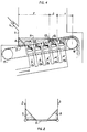
- Figure 1 shows schematically in longitudinal section such an installation.
- Figure 2 is a cross-sectional view of this installation.
- the reference 1 designates the front wall 1 of the installation and the references 2 and 3 its side walls.
- the wall 1 is provided with a pipe 4 for supplying fuel in the form of particles from a not shown crushing device.
- a grid 5 inclined upwards from front to rear is arranged between the walls 2 and 3 at a certain distance from them.
- This grid advantageously constituted by the upper strand of a endless chain, receives the fuel leaving the pipe 4.
- the reference 6 designates the fuel slope formed against the wall 1
- the references 7 and 8 designate the slope formed against the side walls 2 and 3.
- the boxes 9a, 9b and 9c deliver an air flow sufficient to cause fluidization of the fuel in the bed 12 which forms above said boxes.
- the boxes 9d and 9e deliver an amount of air insufficient to cause fluidization.
- the area above the casing 9d constitutes an ash sedimentation area which will be discussed more explicitly below, while the area above the casing 9e constitutes, in a manner known per se, an area for transporting ash and unclog grid 5.
- Each box is associated with a valve for adjusting the air flow rate coming from a fan, not shown, these valves are respectively marked 13a, 13b, 13c, 13d, 13e.
- These valves make it possible to distribute the total air flow so that this flow decreases progressively from front to rear, which causes inside the bed 12, a methodical flow of fuel.
- the term “methodical flow” is understood to mean a flow from the front to the rear at a speed such that the residence time of the fuel in the bed 12 is equal to the minimum necessary to ensure its complete combustion, while the only ashes are brought to the rear end of the bed 12 where they pass from the fluidization zone F to the sedimentation zone S.
- the ashes are deposited along a slope 14 whose height is equal to that of the fixed layer extracted from the bed by the displacement of the grid 5 towards the transport zone T.
- the embankment 14 extends over the entire length of the sedimentation zone S and it is renewed in successive sections as the grid advances .
- the sedimentation zone S extends over the entire length of the box 9d, from a fixed point 15 materialized by the trace on the plane of the figure of the upper end of the front face of the box 9d.
- the sedimentation zone S moves and no longer covers only the caisson 9c, the transport zone T covering the caissons 9d and 9e.
- the sedimentation zone S moves and covers the only box 9e, while the very short transport zone T is devoid of boxes.
- the level N and the extent of the fluidization zone F are therefore adjusted by modifying the position of point 15 by means of the valves 13a, 13b, 13c, 3d and 13e.
- the speed of the grate can be adjusted for a given fuel flow rate and an ash content thereof, in order to act correlatively on the minimum stay time of the fuel in the bed 12 for combustion. complete, as well as to obtain a fixed layer of optimum thickness in the transport zone T.
- the number of boxes may differ from five. It is even advantageous, to ensure a finer adjustment of the position of point 15, to provide, for a given grid length, a greater number of boxes of shorter length.
- valves 13a, 13b, 13c, 13d, 13e adjustable according to the various parameters (ash content, speed of the grate, height of the layer, distribution of the air flow and fuel). These different parameters can be recorded on the panel of a control panel.
Landscapes
- Engineering & Computer Science (AREA)
- Chemical & Material Sciences (AREA)
- Combustion & Propulsion (AREA)
- Mechanical Engineering (AREA)
- General Engineering & Computer Science (AREA)
- Fluidized-Bed Combustion And Resonant Combustion (AREA)
- Devices And Processes Conducted In The Presence Of Fluids And Solid Particles (AREA)
Claims (4)
Priority Applications (1)
| Application Number | Priority Date | Filing Date | Title |
|---|---|---|---|
| AT83401189T ATE15535T1 (de) | 1982-06-15 | 1983-06-10 | Verfahren zur verbrennung von minderwertigen brennstoffen im wirbelbett insbesondere von brandschiefer oder bituminoesem tonschiefer. |
Applications Claiming Priority (2)
| Application Number | Priority Date | Filing Date | Title |
|---|---|---|---|
| FR8210385A FR2528543A1 (fr) | 1982-06-15 | 1982-06-15 | Procede de combustion en lit fluidise de combustibles pauvres, notamment de schistes houillers ou bitumineux, et installation pour la mise en oeuvre de ce procede |
| FR8210385 | 1982-06-15 |
Publications (2)
| Publication Number | Publication Date |
|---|---|
| EP0099281A1 EP0099281A1 (de) | 1984-01-25 |
| EP0099281B1 true EP0099281B1 (de) | 1985-09-11 |
Family
ID=9275002
Family Applications (1)
| Application Number | Title | Priority Date | Filing Date |
|---|---|---|---|
| EP83401189A Expired EP0099281B1 (de) | 1982-06-15 | 1983-06-10 | Verfahren zur Verbrennung von minderwertigen Brennstoffen im Wirbelbett insbesondere von Brandschiefer oder bituminösem Tonschiefer |
Country Status (4)
| Country | Link |
|---|---|
| EP (1) | EP0099281B1 (de) |
| AT (1) | ATE15535T1 (de) |
| DE (1) | DE3360786D1 (de) |
| FR (1) | FR2528543A1 (de) |
Families Citing this family (3)
| Publication number | Priority date | Publication date | Assignee | Title |
|---|---|---|---|---|
| FR2553496B1 (fr) * | 1983-10-13 | 1988-02-26 | Fives Cail Babcock | Dispositif de combustion en lit fluidise de combustibles pauvres, notamment de schistes houillers ou bitumineux |
| FR2578629B1 (fr) * | 1985-03-11 | 1987-04-30 | Fives Cail Babcock | Dispositif de combustion ou de gazeification a lit fluidise comportant une chaine sans fin pour l'extraction des cendres |
| CN104848212B (zh) * | 2015-05-27 | 2017-04-05 | 山西大学 | 一种煤矸石固硫控温燃烧与灰渣高效耦合利用的方法 |
Family Cites Families (5)
| Publication number | Priority date | Publication date | Assignee | Title |
|---|---|---|---|---|
| FR1092540A (fr) * | 1953-10-29 | 1955-04-22 | Cie Ind De Procedes Et D Appli | Perfectionnements aux procédés de réalisation de réactions chimiques en phase fluidisée et dispositif pour leur mise en oeuvre |
| FR1440039A (fr) * | 1965-04-13 | 1966-05-27 | Cie Ind De Procedes Et D Appli | Grille mécanique à chaîne pendante pour la combustion en lit fluidisé |
| US3625164A (en) * | 1971-04-21 | 1971-12-07 | Air Prod & Chem | Combustion of high-sulfur coal in a fluidized bed reactor |
| US3776150A (en) * | 1972-03-06 | 1973-12-04 | Awt Systems Inc | Fluidized bed system for solid wastes |
| FR2261051B1 (de) * | 1974-02-14 | 1980-08-08 | Activit Sa |
-
1982
- 1982-06-15 FR FR8210385A patent/FR2528543A1/fr active Granted
-
1983
- 1983-06-10 EP EP83401189A patent/EP0099281B1/de not_active Expired
- 1983-06-10 DE DE8383401189T patent/DE3360786D1/de not_active Expired
- 1983-06-10 AT AT83401189T patent/ATE15535T1/de not_active IP Right Cessation
Also Published As
| Publication number | Publication date |
|---|---|
| DE3360786D1 (en) | 1985-10-17 |
| FR2528543A1 (fr) | 1983-12-16 |
| ATE15535T1 (de) | 1985-09-15 |
| FR2528543B1 (de) | 1985-03-15 |
| EP0099281A1 (de) | 1984-01-25 |
Similar Documents
| Publication | Publication Date | Title |
|---|---|---|
| EP1532411B1 (de) | Vorrichtung zum trocknen von produkten wie insbesondere kläranlagenschlamm | |
| FR2519877A1 (fr) | Grille de fluidisation ainsi que foyer de combustion a grille inferieure de soufflage d'air et procede de traitement de matiere particulaire dans une chambre de fluidisation et/ou d'entrainement | |
| FR2558241A1 (fr) | Chaudiere a bois comportant une chambre de prechauffage du comburant | |
| EP0099281B1 (de) | Verfahren zur Verbrennung von minderwertigen Brennstoffen im Wirbelbett insbesondere von Brandschiefer oder bituminösem Tonschiefer | |
| CH639187A5 (fr) | Chaudiere, notamment pour installation de chauffage. | |
| FR2487847A1 (fr) | Procede et installation de gazeification de matieres d'origine vegetale | |
| EP0138692B1 (de) | Vorrichtung zur Verbrennung von minderwertigen Brennstoffen im Wirbelbett, insbesondere von Brandschiefer oder bituminösem Tonschiefer | |
| FR2850157A1 (fr) | Reacteur a lit fluidise a circulation | |
| EP0123596B1 (de) | Wirbelvorrichtung mit innerem Wärmetauscher | |
| FR2635274A1 (fr) | Appareil a lit fluidise en circulation | |
| FR2601933A1 (fr) | Installation d'evacuation pour silos contenant des produits en vrac evacues par de l'air souffle | |
| FR2463360A1 (fr) | Installation de combustion a combustibles solides | |
| FR2896709A1 (fr) | Separateur de solides en particulier pour installation de combustion | |
| EP4055325B1 (de) | Verbrennungsvorrichtung | |
| FR2555710A1 (fr) | Procede pour la combustion ou la gazeification en lit fluidise de combustibles solides et dispositif pour la mise en oeuvre de ce procede | |
| FR3101395A1 (fr) | Système de gazéification et/ou de combustion équipant une installation de gazéification et/ou de combustion | |
| EP0094893B1 (de) | Verfahren und Vorrichtung zur Behandlung eines festen kleinstückigen Materials | |
| FR2547393A1 (fr) | Chambre de combustion pour combustibles solides | |
| FR2542066A1 (fr) | Procede pour bruler des charbons gonflants en lit fluidise a grille mecanique mobile, et foyer adapte a la mise en oeuvre de ce procede | |
| FR2508140A1 (fr) | Installation de chauffage a combustible solide par exemple pulverulent, comportant un dispositif de fond de foyer ajoure | |
| BE532757A (de) | ||
| EP2573462A1 (de) | Heizanlage für Festbrennstoff vom Typ individualisierte Elemente | |
| BE518026A (de) | ||
| BE518024A (de) | ||
| FR2549939A1 (fr) | Chaudiere a chargement automatique pour combustibles a base de bois fragmente |
Legal Events
| Date | Code | Title | Description |
|---|---|---|---|
| PUAI | Public reference made under article 153(3) epc to a published international application that has entered the european phase |
Free format text: ORIGINAL CODE: 0009012 |
|
| AK | Designated contracting states |
Designated state(s): AT BE CH DE GB IT LI LU NL SE |
|
| 17P | Request for examination filed |
Effective date: 19840210 |
|
| ITF | It: translation for a ep patent filed | ||
| GRAA | (expected) grant |
Free format text: ORIGINAL CODE: 0009210 |
|
| AK | Designated contracting states |
Designated state(s): AT BE CH DE GB IT LI LU NL SE |
|
| REF | Corresponds to: |
Ref document number: 15535 Country of ref document: AT Date of ref document: 19850915 Kind code of ref document: T |
|
| REF | Corresponds to: |
Ref document number: 3360786 Country of ref document: DE Date of ref document: 19851017 |
|
| PLBE | No opposition filed within time limit |
Free format text: ORIGINAL CODE: 0009261 |
|
| STAA | Information on the status of an ep patent application or granted ep patent |
Free format text: STATUS: NO OPPOSITION FILED WITHIN TIME LIMIT |
|
| 26N | No opposition filed | ||
| ITTA | It: last paid annual fee | ||
| PGFP | Annual fee paid to national office [announced via postgrant information from national office to epo] |
Ref country code: BE Payment date: 19940428 Year of fee payment: 12 |
|
| PGFP | Annual fee paid to national office [announced via postgrant information from national office to epo] |
Ref country code: SE Payment date: 19940524 Year of fee payment: 12 |
|
| PGFP | Annual fee paid to national office [announced via postgrant information from national office to epo] |
Ref country code: LU Payment date: 19940531 Year of fee payment: 12 |
|
| PGFP | Annual fee paid to national office [announced via postgrant information from national office to epo] |
Ref country code: GB Payment date: 19940601 Year of fee payment: 12 |
|
| PGFP | Annual fee paid to national office [announced via postgrant information from national office to epo] |
Ref country code: CH Payment date: 19940607 Year of fee payment: 12 |
|
| PGFP | Annual fee paid to national office [announced via postgrant information from national office to epo] |
Ref country code: AT Payment date: 19940624 Year of fee payment: 12 |
|
| PGFP | Annual fee paid to national office [announced via postgrant information from national office to epo] |
Ref country code: NL Payment date: 19940630 Year of fee payment: 12 |
|
| EPTA | Lu: last paid annual fee | ||
| PGFP | Annual fee paid to national office [announced via postgrant information from national office to epo] |
Ref country code: DE Payment date: 19940829 Year of fee payment: 12 |
|
| EAL | Se: european patent in force in sweden |
Ref document number: 83401189.2 |
|
| PG25 | Lapsed in a contracting state [announced via postgrant information from national office to epo] |
Ref country code: LU Free format text: LAPSE BECAUSE OF NON-PAYMENT OF DUE FEES Effective date: 19950610 Ref country code: GB Effective date: 19950610 Ref country code: AT Effective date: 19950610 |
|
| PG25 | Lapsed in a contracting state [announced via postgrant information from national office to epo] |
Ref country code: SE Effective date: 19950611 |
|
| PG25 | Lapsed in a contracting state [announced via postgrant information from national office to epo] |
Ref country code: LI Effective date: 19950630 Ref country code: CH Effective date: 19950630 Ref country code: BE Effective date: 19950630 |
|
| BERE | Be: lapsed |
Owner name: FIVES-CAIL BABCOCK S.A. Effective date: 19950630 |
|
| PG25 | Lapsed in a contracting state [announced via postgrant information from national office to epo] |
Ref country code: NL Effective date: 19960101 |
|
| GBPC | Gb: european patent ceased through non-payment of renewal fee |
Effective date: 19950610 |
|
| REG | Reference to a national code |
Ref country code: CH Ref legal event code: PL |
|
| NLV4 | Nl: lapsed or anulled due to non-payment of the annual fee |
Effective date: 19960101 |
|
| PG25 | Lapsed in a contracting state [announced via postgrant information from national office to epo] |
Ref country code: DE Effective date: 19960301 |
|
| EUG | Se: european patent has lapsed |
Ref document number: 83401189.2 |