EP0099281B1 - Process for the combustion in a fluidized bed of low grade fuels, especially coal or oil shales - Google Patents
Process for the combustion in a fluidized bed of low grade fuels, especially coal or oil shales Download PDFInfo
- Publication number
- EP0099281B1 EP0099281B1 EP83401189A EP83401189A EP0099281B1 EP 0099281 B1 EP0099281 B1 EP 0099281B1 EP 83401189 A EP83401189 A EP 83401189A EP 83401189 A EP83401189 A EP 83401189A EP 0099281 B1 EP0099281 B1 EP 0099281B1
- Authority
- EP
- European Patent Office
- Prior art keywords
- fluidized bed
- grate
- zone
- fluidization
- fuel
- Prior art date
- Legal status (The legal status is an assumption and is not a legal conclusion. Google has not performed a legal analysis and makes no representation as to the accuracy of the status listed.)
- Expired
Links
Images
Classifications
-
- F—MECHANICAL ENGINEERING; LIGHTING; HEATING; WEAPONS; BLASTING
- F23—COMBUSTION APPARATUS; COMBUSTION PROCESSES
- F23C—METHODS OR APPARATUS FOR COMBUSTION USING FLUID FUEL OR SOLID FUEL SUSPENDED IN A CARRIER GAS OR AIR
- F23C10/00—Fluidised bed combustion apparatus
- F23C10/002—Fluidised bed combustion apparatus for pulverulent solid fuel
-
- F—MECHANICAL ENGINEERING; LIGHTING; HEATING; WEAPONS; BLASTING
- F23—COMBUSTION APPARATUS; COMBUSTION PROCESSES
- F23C—METHODS OR APPARATUS FOR COMBUSTION USING FLUID FUEL OR SOLID FUEL SUSPENDED IN A CARRIER GAS OR AIR
- F23C10/00—Fluidised bed combustion apparatus
- F23C10/18—Details; Accessories
- F23C10/20—Inlets for fluidisation air, e.g. grids; Bottoms
-
- F—MECHANICAL ENGINEERING; LIGHTING; HEATING; WEAPONS; BLASTING
- F23—COMBUSTION APPARATUS; COMBUSTION PROCESSES
- F23C—METHODS OR APPARATUS FOR COMBUSTION USING FLUID FUEL OR SOLID FUEL SUSPENDED IN A CARRIER GAS OR AIR
- F23C10/00—Fluidised bed combustion apparatus
- F23C10/18—Details; Accessories
- F23C10/24—Devices for removal of material from the bed
-
- F—MECHANICAL ENGINEERING; LIGHTING; HEATING; WEAPONS; BLASTING
- F23—COMBUSTION APPARATUS; COMBUSTION PROCESSES
- F23H—GRATES; CLEANING OR RAKING GRATES
- F23H11/00—Travelling-grates
- F23H11/12—Travelling-grates inclined travelling grates; Stepped travelling grates
Abstract
Description
La présente invention concerne la combustion en lit fluidisé de combustibles pauvres, notamment de schistes houillers ou bitumineux.The present invention relates to the combustion in a fluidized bed of lean fuels, in particular coal or bituminous shales.
La technique de la combustion en lit fluidisé est connue depuis longtemps. On utilise avantageusement à cet effet une installation constituée par une paroi avant sensiblement verticale, munie d'un dispositif d'alimentation en combustible sous forme de particules, deux parois latérales, une grille mobile inclinée vers le haut de l'avant à l'arrière, ladite grille étant aménagée entre les deux parois latérales, à une certaine distance de celles-ci, et une pluralité de caissons de soufflage d'air ou de tout autre gaz comburant disposés sous la grille. Une installation de ce genre est décrite dans le brevet FR-A-1 092 540. Le brevet FR-A-1 440 039 décrit une installation similaire comprenant en outre, une pluralité de vannes, chacune d'elles étant affectée à un caisson de soufflage particulier.The technique of combustion in a fluidized bed has been known for a long time. An installation is advantageously used for this purpose, consisting of a substantially vertical front wall, provided with a fuel supply device in the form of particles, two side walls, a movable grid inclined upwards from front to rear. , said grid being arranged between the two side walls, at a certain distance from the latter, and a plurality of boxes for blowing air or any other oxidizing gas disposed under the grid. An installation of this kind is described in patent FR-A-1,092,540. Patent FR-A-1,440,039 describes a similar installation further comprising a plurality of valves, each of which being assigned to a box of particular blowing.
Dans les applications courantes de telles installations, on fait appel à des combustibles relativement riches brûlant à une température d'au moins 1200°C. A une telle température, les cendres s'agglomèrent sous forme de mâchefers qui se déposent au fond du lit sur toute la longueur de celui-ci. Ces agglomérats sont extraits par la grille elle-même à travers la surface libre du lit, à l'arrière de la zone de fluidisation. Un soufflage modéré, insuffisant pour provoquer une fluidisation, peut être avantageusement maintenu vers l'arrière de la grille, à un niveau supérieur à celui du lit, pour éviter que les agglomérats transportés par la grille ne viennent se coller sur celle-ci.In current applications of such installations, relatively rich fuels are used which burn at a temperature of at least 1200 ° C. At such a temperature, the ash agglomerates in the form of bottom ash which is deposited at the bottom of the bed over the entire length thereof. These agglomerates are extracted by the grid itself through the free surface of the bed, behind the fluidization zone. A moderate blowing, insufficient to cause fluidization, can advantageously be maintained towards the rear of the grid, at a level higher than that of the bed, to prevent the agglomerates transported by the grid from sticking to it.
On a déjà pensé à étendre le domaine d'application de cette technique à la combustion de combustibles pauvres à forte teneur en cendres.It has already been thought of extending the field of application of this technique to the combustion of poor fuels with a high ash content.
La difficulté réside en ce que la température de combustion s'établit à une valeur souvent inférieure à 1000°C et de toute façon inférieure à la température nécessaire à la formation d'agglomérats. Il devient alors pratiquement impossible d'évacuer les cendres, ou tout au moins leur évacuation entraîne l'évacuation simultanée d'une quantité relativement importante d'imbrûlés. Le rendement thermique de la combustion est très médiocre, ce qui est d'autant plus gênant que la teneur en cendres est élévée.The difficulty is that the combustion temperature is often less than 1000 ° C and in any case less than the temperature necessary for the formation of agglomerates. It then becomes practically impossible to evacuate the ashes, or at least their evacuation results in the simultaneous evacuation of a relatively large quantity of unburnt materials. The thermal efficiency of combustion is very poor, which is all the more annoying the higher the ash content.
L'invention a essentiellement pour but de surmonter cette difficulté.The object of the invention is essentially to overcome this difficulty.
Elle consiste surtout à former entre la zone de fluidisation et la zone de transport, une zone de sédimentation intermédiaire, et à établir une circulation méthodique du combustible de manière à amener dans ladite zone de sédimentation la quasi totalité des cendres qui s'y déposent après que le combustible ait séjourné dans le lit fluidisé le temps minimal nécessaire à sa combustion complète.It consists above all in forming between the fluidization zone and the transport zone, an intermediate sedimentation zone, and in establishing a methodical circulation of the fuel so as to bring into said sedimentation zone almost all of the ash which is deposited there after the fuel has remained in the fluidized bed for the minimum time necessary for its complete combustion.
L'invention a plus précisément pour objet un procédé de combustion en lit fluidisé de combustibles pauvres, notamment de schistes houillers ou bitumineux, sur une grille inclinée vers le haut de l'avant à l'arrière, des caissons de soufflage d'air ou de tout autre gaz comburant étant aménagés au-dessous de la grille qui est alimentée par l'avant en combustible, la partie avant de ladite grille constituant une zone de fluidisation, et la partie arrière de ladite grille constituant, à un niveau supérieur à celui du lit fluidisé, une zone de transport des cendres sous forme de couche fixe, caractérisé en ce que:
- - l'on maintient à partir d'un point fixe, à l'arrière de la zone de fluidisation, un soufflage insuffisant pour provoquer une fluidisation, de sorte qu'il se forme entre la zone de fluidisation et la zone de transport, une zone intermédiaire de sédimentation dans laquelle les cendres se déposent suivant un talus, ledit talus qui s'étend sur toute la longueur de la zone de sédimentation, se renouvelant par tranches parallèles successives au fur et à mesure du déplacement de la grille, et
- - l'on répartit le débit d'air de soufflage dans les caissons de manière à créer un écoulement méthodique du combustible de l'avant vers l'arrière du lit fluidisé, permettant ainsi l'amenée des cendres dans la zone de sédimentation en vue de leur extraction.
- - Maintaining from a fixed point, behind the fluidization zone, an insufficient blowing to cause fluidization, so that it forms between the fluidization zone and the transport zone, a intermediate sedimentation zone in which the ashes are deposited along an embankment, said embankment which extends over the entire length of the sedimentation zone, being renewed by successive parallel sections as the grate moves, and
- - the blowing air flow is distributed in the boxes so as to create a methodical flow of fuel from the front to the rear of the fluidized bed, thus allowing the ashes to be brought into the sedimentation zone in view of their extraction.
L'on règle le niveau et l'étendue du lit fluidisé par modification de la position dudit point fixe.The level and the extent of the fluidized bed are adjusted by modifying the position of said fixed point.
On règle la vitesse de la grille, pour un débit de combustible et une teneur en cendres donnés, afin d'obtenir un temps minimal de séjour du combustible dans le lit fluidisé pour une combustion complète, et une épaisseur le couche fixe de cendres prédéterminée.The speed of the grate is adjusted, for a given fuel flow rate and a given ash content, in order to obtain a minimum residence time of the fuel in the fluidized bed for complete combustion, and a predetermined thickness of the fixed layer of ash.
On règle le niveau et l'étendue du lit fluidisé en modifiant le nombre de caissons mis en service avec un débit suiffisant pour provoquer une fluidisation, d'une part, et la répartition du débit d'air entre les dits caissons, d'autre part.The level and the extent of the fluidized bed are adjusted by modifying the number of boxes put into service with a sufficient flow rate to cause fluidization, on the one hand, and the distribution of the air flow rate between said boxes, on the other hand go.
L'invention sera mieux comprise en se référant à la description qui suit, faite en regard des dessins annexés, concernant une forme de réalisation d'une installation pour la mise en oeuvre du procédé selon l'invention, donnée à titre d'exemple non limitatif.The invention will be better understood by referring to the description which follows, given with reference to the appended drawings, concerning an embodiment of an installation for implementing the method according to the invention, given by way of example not limiting.
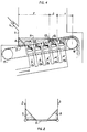
La figure 1 représente schématiquement en coupe longitudinale une telle installation.Figure 1 shows schematically in longitudinal section such an installation.
La figure 2 est une vue en coupe transversale de cette installation.Figure 2 is a cross-sectional view of this installation.
Sur les figures, le repère 1 désigne la paroi avant 1 de l'installation et les repères 2 et 3 ses parois latérales. La paroi 1 est munie d'une tubulure 4 d'alimentation en combustible sous forme de particules en provenance d'un dispositif de concassage non représenté.In the figures, the reference 1 designates the front wall 1 of the installation and the references 2 and 3 its side walls. The wall 1 is provided with a pipe 4 for supplying fuel in the form of particles from a not shown crushing device.
Une grille 5 inclinée vers le haut de l'avant vers l'arrière est aménagée entre les parois 2 et 3 à une certaine distance de celles-ci. Cette grille avantageusement constituée par le brin supérieur d'une chaîne sans fin, reçoit le combustible sortant de la tubulure 4.A
Le repère 6 désigne le talus de combustible formé contre la paroi 1, tandis que les repères 7 et 8 désignent les talus formés contre les parois latérales 2 et 3.The reference 6 designates the fuel slope formed against the wall 1, while the references 7 and 8 designate the slope formed against the side walls 2 and 3.
Au-dessous de la grille 5 sont déposés des caissons de soufflage d'air ou de tout autre gaz comburant. Ces caissons, au nombre de cinq dans l'exemple représenté, sont respectivement repérés 9a, 9b, 9c, 9d et 9e de l'avant vers l'arrière de la grille entre les tambours 10 et 11 de celle-ci.Below the
Seuls les caissons 9a, 9b et 9c délivrent un débit d'air suffisant pour provoquer une fluidisation du combustible dans le lit 12 qui se forme au-dessus desdits caissons. Les caissons 9d et 9e délivrent une quantité d'air insuffisante pour provoquer une fluidisation. La zone située au-dessus du caisson 9d constitue une zone de sédimentation des cendres dont il sera parlé plus explicitement ci-après, tandis que la zone située au-dessus du caisson 9e constitue, de façon connue en soi, une zone de transport des cendres et de décolmatage de la grille 5.Only the boxes 9a, 9b and 9c deliver an air flow sufficient to cause fluidization of the fuel in the
Chaque caisson est associé à une vanne de réglage du débit d'air en provenance d'un ventilateur, non représenté, ces vannes sont respectivement repérées 13a, 13b, 13c, 13d, 13e. Ces vannes permettent de répartir le débit d'air total de telle sorte que ce débit diminue progressivement de l'avant vers l'arrière, ce qui provoque à l'intérieur du lit 12, un écoulement méthodique du combustible. On entend par écoulement méthodique, un écoulement de l'avant vers l'arrière à une vitesse telle que le temps de séjour du combustible dans le lit 12 soit égal au minimum nécessaire pour assurer sa combustion complète, tandis que les seules cendres sont amenées à l'extrémité arrière du lit 12 où elles passent de la zone de fluidisation F à la zone de sédimentation S. Dans cette dernière zone les cendres se déposent suivant un talus 14 dont la hauteur est égale à celle de la couche fixe extraite du lit par le déplacement de la grille 5 vers la zone de transport T. Le talus 14 s'étend sur toute la longueur de la zone de sédimentation S et il se renouvelle par tranches successives au fur et à mesure de l'avence- ment de la grille.Each box is associated with a valve for adjusting the air flow rate coming from a fan, not shown, these valves are respectively marked 13a, 13b, 13c, 13d, 13e. These valves make it possible to distribute the total air flow so that this flow decreases progressively from front to rear, which causes inside the
On voit que la zone de sédimentation S s'étend sur toute la longueur du caisson 9d, à partir d'un point fixe 15 matérialisé par la trace sur le plan de la figure de l'extrémité supérieure de la face avant du caisson 9d. On peut modifier la position de ce point vers l'avant en réglant la vanne 13c de telle sorte que le caisson 9c ne délivre plus un débit suffisant pour assurer une fluidisation. La zone de sédimentation S se déplace et ne recouvre plus que le caisson 9c, la zone de transport T recouvrant les caissons 9d et 9e. On peut, bien entendu, déplacer ce point vers l'arrière en admettant au contraire dans le caisson 9d un débit suffisant pour provoquer une fluidisation. La zone de sédimentation S se déplace et recouvre le seul caisson 9e, tandis que la zone de transport T, très courte est démunie de caissons. Le niveau N et l'étendue de la zone de fluidisation F sont donc réglés par modification de la position du point 15 au moyen des vannes 13a, 13b, 13c, 3d et 13e.It can be seen that the sedimentation zone S extends over the entire length of the box 9d, from a
On peut régler, d'autre part, la vitesse de la grille pour un débit de combustible et une teneur en cendres de celui-ci donnés, afin d'agir corrélativement sur le temps minimal de séjour du combustible dans le lit 12 pour une combustion complète, ainsi que pour obtenir une couche fixe d'épaisseur optimale dans la zone de transport T.On the other hand, the speed of the grate can be adjusted for a given fuel flow rate and an ash content thereof, in order to act correlatively on the minimum stay time of the fuel in the
On donnera, ci-après, à titre d'exemple, les caractéristiques d'une installation pilote réalisée par la demanderesse et les résultats d'essais obtenus:

Le nombre de caissons pourra différer de cinq. Il est même avantageux, pour assurer un réglage plus fin de la position du point 15 de prévoir, pour une longueur de grille donnée, un nombre plus important de caissons de plus faible longueur. On peut également envisager, au lieu d'agir sur le nombre des caissons, de prévoir à l'intérieur de chacun d'eux un dispositif de cloisonnement réglable.The number of boxes may differ from five. It is even advantageous, to ensure a finer adjustment of the position of
On peut également pour réalisier un programme donné, prévoir une télécommande des vannes 13a, 13b, 13c, 13d, 13e réglables en fonction des différents paramètres (teneur en cendres, vitesse de la grille, hauteur de la couche, répartition du débit d'air et de combustible). Ces différents paramètres peuvent être enregistrés sur le tableau d'un pupitre de commande.It is also possible to carry out a given program, by providing a remote control of the
Claims (4)
Priority Applications (1)
| Application Number | Priority Date | Filing Date | Title |
|---|---|---|---|
| AT83401189T ATE15535T1 (en) | 1982-06-15 | 1983-06-10 | METHOD OF COMBUSTIONING LOW-QUALITY FUELS IN THE FLUIDIZED BED, ESPECIALLY BURNING SLATE OR BITUMINOUS SLATE. |
Applications Claiming Priority (2)
| Application Number | Priority Date | Filing Date | Title |
|---|---|---|---|
| FR8210385A FR2528543A1 (en) | 1982-06-15 | 1982-06-15 | METHOD OF COMBUSTION OF FLUIDIZED BED OF POOR FUELS, ESPECIALLY HOT OR BITUMINOUS SCHISTES, AND INSTALLATION FOR CARRYING OUT SAID METHOD |
| FR8210385 | 1982-06-15 |
Publications (2)
| Publication Number | Publication Date |
|---|---|
| EP0099281A1 EP0099281A1 (en) | 1984-01-25 |
| EP0099281B1 true EP0099281B1 (en) | 1985-09-11 |
Family
ID=9275002
Family Applications (1)
| Application Number | Title | Priority Date | Filing Date |
|---|---|---|---|
| EP83401189A Expired EP0099281B1 (en) | 1982-06-15 | 1983-06-10 | Process for the combustion in a fluidized bed of low grade fuels, especially coal or oil shales |
Country Status (4)
| Country | Link |
|---|---|
| EP (1) | EP0099281B1 (en) |
| AT (1) | ATE15535T1 (en) |
| DE (1) | DE3360786D1 (en) |
| FR (1) | FR2528543A1 (en) |
Families Citing this family (3)
| Publication number | Priority date | Publication date | Assignee | Title |
|---|---|---|---|---|
| FR2553496B1 (en) * | 1983-10-13 | 1988-02-26 | Fives Cail Babcock | FLUIDIZED BED COMBUSTION DEVICE FOR POOR FUELS, ESPECIALLY COAL OR BITUMINOUS SHELLS |
| FR2578629B1 (en) * | 1985-03-11 | 1987-04-30 | Fives Cail Babcock | FLUIDIZED BED COMBUSTION OR GASIFYING DEVICE COMPRISING AN ENDLESS CHAIN FOR ASH REMOVAL |
| CN104848212B (en) * | 2015-05-27 | 2017-04-05 | 山西大学 | The method that a kind of solid sulphur controlled temperature combustion of gangue is utilized with lime-ash efficient coupling |
Family Cites Families (5)
| Publication number | Priority date | Publication date | Assignee | Title |
|---|---|---|---|---|
| FR1092540A (en) * | 1953-10-29 | 1955-04-22 | Cie Ind De Procedes Et D Appli | Improvements in processes for carrying out chemical reactions in the fluidized phase and device for their implementation |
| FR1440039A (en) * | 1965-04-13 | 1966-05-27 | Cie Ind De Procedes Et D Appli | Mechanical hanging chain grate for fluidized bed combustion |
| US3625164A (en) * | 1971-04-21 | 1971-12-07 | Air Prod & Chem | Combustion of high-sulfur coal in a fluidized bed reactor |
| US3776150A (en) * | 1972-03-06 | 1973-12-04 | Awt Systems Inc | Fluidized bed system for solid wastes |
| FR2261051B1 (en) * | 1974-02-14 | 1980-08-08 | Activit Sa |
-
1982
- 1982-06-15 FR FR8210385A patent/FR2528543A1/en active Granted
-
1983
- 1983-06-10 AT AT83401189T patent/ATE15535T1/en not_active IP Right Cessation
- 1983-06-10 EP EP83401189A patent/EP0099281B1/en not_active Expired
- 1983-06-10 DE DE8383401189T patent/DE3360786D1/en not_active Expired
Also Published As
| Publication number | Publication date |
|---|---|
| DE3360786D1 (en) | 1985-10-17 |
| EP0099281A1 (en) | 1984-01-25 |
| FR2528543A1 (en) | 1983-12-16 |
| ATE15535T1 (en) | 1985-09-15 |
| FR2528543B1 (en) | 1985-03-15 |
Similar Documents
| Publication | Publication Date | Title |
|---|---|---|
| EP1532411B1 (en) | Device for drying products such as in particular purifying station sludge | |
| FR2519877A1 (en) | FLUIDIZING GRID AND LOW AIR BLOWING COMBUSTION FIREPLACE AND METHOD OF TREATING PARTICULATE MATERIAL IN A FLUIDIZING AND / OR DRIVING CHAMBER | |
| EP0099281B1 (en) | Process for the combustion in a fluidized bed of low grade fuels, especially coal or oil shales | |
| CH639187A5 (en) | BOILER, ESPECIALLY FOR A HEATING SYSTEM. | |
| FR2558241A1 (en) | WOOD BOILER COMPRISING A FUEL PREHEATING CHAMBER | |
| FR2487847A1 (en) | PROCESS AND PLANT FOR GASIFICATION OF MATERIALS OF PLANT ORIGIN | |
| FR2896709A1 (en) | Metal oxide particles and carbonated residues separator for carbonated residue combustion installation, has vertical deflector constituting two compartments, in which one of compartments comprises lateral deflector deviating path | |
| EP0057895A2 (en) | Device for the direct ignition of poor pulverised solid fuel in cold combustion chambers | |
| EP0138692B1 (en) | Device for the combustion in a fluidized bed of low-grade fuels, especially black batt or bind | |
| FR2850157A1 (en) | FLUIDIZED CIRCULATION BED REACTOR | |
| EP0123596A1 (en) | Fluidising device having an internal heat exchanger | |
| FR2601933A1 (en) | EVACUATION INSTALLATION FOR SILOS CONTAINING BULK PRODUCTS DAMAGED BY BREATHING AIR | |
| FR2463360A1 (en) | SOLID FUEL COMBUSTION FACILITY | |
| FR3101395A1 (en) | Gasification and / or combustion system equipping a gasification and / or combustion installation | |
| EP4055325B1 (en) | Combustion device | |
| EP0094893B1 (en) | Process and installation for solid small-sized materials | |
| EP0126001B1 (en) | Process and apparatus for the treatment of fuel in a fluidized bed | |
| EP0885946B1 (en) | Apparatus and process for the management of gaseous streams in a distillation plant | |
| FR2555710A1 (en) | Method for burning or gasifying solid fuels in a fluidised bed, and device for the implementation of this method | |
| EP2573462A1 (en) | Heating system fired with individualised solid fuel elements | |
| BE532757A (en) | ||
| BE518026A (en) | ||
| FR2512925A1 (en) | Fluidised bed air distributor plate - is water cooled and has upstanding air discharge pipes to enable low alloy to be used | |
| BE518024A (en) | ||
| FR2682741A1 (en) | Small capacity household waste incinerator - is easily transportable by dismantling quickly into slot in vertical sections each suitable for one man back pack |
Legal Events
| Date | Code | Title | Description |
|---|---|---|---|
| PUAI | Public reference made under article 153(3) epc to a published international application that has entered the european phase |
Free format text: ORIGINAL CODE: 0009012 |
|
| AK | Designated contracting states |
Designated state(s): AT BE CH DE GB IT LI LU NL SE |
|
| 17P | Request for examination filed |
Effective date: 19840210 |
|
| ITF | It: translation for a ep patent filed |
Owner name: BARZANO' E ZANARDO MILANO S.P.A. |
|
| GRAA | (expected) grant |
Free format text: ORIGINAL CODE: 0009210 |
|
| AK | Designated contracting states |
Designated state(s): AT BE CH DE GB IT LI LU NL SE |
|
| REF | Corresponds to: |
Ref document number: 15535 Country of ref document: AT Date of ref document: 19850915 Kind code of ref document: T |
|
| REF | Corresponds to: |
Ref document number: 3360786 Country of ref document: DE Date of ref document: 19851017 |
|
| PLBE | No opposition filed within time limit |
Free format text: ORIGINAL CODE: 0009261 |
|
| STAA | Information on the status of an ep patent application or granted ep patent |
Free format text: STATUS: NO OPPOSITION FILED WITHIN TIME LIMIT |
|
| 26N | No opposition filed | ||
| ITTA | It: last paid annual fee | ||
| PGFP | Annual fee paid to national office [announced via postgrant information from national office to epo] |
Ref country code: BE Payment date: 19940428 Year of fee payment: 12 |
|
| PGFP | Annual fee paid to national office [announced via postgrant information from national office to epo] |
Ref country code: SE Payment date: 19940524 Year of fee payment: 12 |
|
| PGFP | Annual fee paid to national office [announced via postgrant information from national office to epo] |
Ref country code: LU Payment date: 19940531 Year of fee payment: 12 |
|
| PGFP | Annual fee paid to national office [announced via postgrant information from national office to epo] |
Ref country code: GB Payment date: 19940601 Year of fee payment: 12 |
|
| PGFP | Annual fee paid to national office [announced via postgrant information from national office to epo] |
Ref country code: CH Payment date: 19940607 Year of fee payment: 12 |
|
| PGFP | Annual fee paid to national office [announced via postgrant information from national office to epo] |
Ref country code: AT Payment date: 19940624 Year of fee payment: 12 |
|
| PGFP | Annual fee paid to national office [announced via postgrant information from national office to epo] |
Ref country code: NL Payment date: 19940630 Year of fee payment: 12 |
|
| EPTA | Lu: last paid annual fee | ||
| PGFP | Annual fee paid to national office [announced via postgrant information from national office to epo] |
Ref country code: DE Payment date: 19940829 Year of fee payment: 12 |
|
| EAL | Se: european patent in force in sweden |
Ref document number: 83401189.2 |
|
| PG25 | Lapsed in a contracting state [announced via postgrant information from national office to epo] |
Ref country code: LU Free format text: LAPSE BECAUSE OF NON-PAYMENT OF DUE FEES Effective date: 19950610 Ref country code: GB Effective date: 19950610 Ref country code: AT Effective date: 19950610 |
|
| PG25 | Lapsed in a contracting state [announced via postgrant information from national office to epo] |
Ref country code: SE Effective date: 19950611 |
|
| PG25 | Lapsed in a contracting state [announced via postgrant information from national office to epo] |
Ref country code: LI Effective date: 19950630 Ref country code: CH Effective date: 19950630 Ref country code: BE Effective date: 19950630 |
|
| BERE | Be: lapsed |
Owner name: FIVES-CAIL BABCOCK S.A. Effective date: 19950630 |
|
| PG25 | Lapsed in a contracting state [announced via postgrant information from national office to epo] |
Ref country code: NL Effective date: 19960101 |
|
| GBPC | Gb: european patent ceased through non-payment of renewal fee |
Effective date: 19950610 |
|
| REG | Reference to a national code |
Ref country code: CH Ref legal event code: PL |
|
| NLV4 | Nl: lapsed or anulled due to non-payment of the annual fee |
Effective date: 19960101 |
|
| PG25 | Lapsed in a contracting state [announced via postgrant information from national office to epo] |
Ref country code: DE Effective date: 19960301 |
|
| EUG | Se: european patent has lapsed |
Ref document number: 83401189.2 |