EP0099064A1 - Verfahren und Vorrichtung für die Befestigung von Endstopteilen an einem teilbaren Reissverschluss - Google Patents
Verfahren und Vorrichtung für die Befestigung von Endstopteilen an einem teilbaren Reissverschluss Download PDFInfo
- Publication number
- EP0099064A1 EP0099064A1 EP83106618A EP83106618A EP0099064A1 EP 0099064 A1 EP0099064 A1 EP 0099064A1 EP 83106618 A EP83106618 A EP 83106618A EP 83106618 A EP83106618 A EP 83106618A EP 0099064 A1 EP0099064 A1 EP 0099064A1
- Authority
- EP
- European Patent Office
- Prior art keywords
- pin
- pin fitting
- gripper
- fitting
- stringer
- Prior art date
- Legal status (The legal status is an assumption and is not a legal conclusion. Google has not performed a legal analysis and makes no representation as to the accuracy of the status listed.)
- Granted
Links
Images


Classifications
-
- A—HUMAN NECESSITIES
- A44—HABERDASHERY; JEWELLERY
- A44B—BUTTONS, PINS, BUCKLES, SLIDE FASTENERS, OR THE LIKE
- A44B19/00—Slide fasteners
- A44B19/42—Making by processes not fully provided for in one other class, e.g. B21D53/50, B21F45/18, B22D17/16, B29D5/00
- A44B19/60—Applying end stops upon stringer tapes
-
- Y—GENERAL TAGGING OF NEW TECHNOLOGICAL DEVELOPMENTS; GENERAL TAGGING OF CROSS-SECTIONAL TECHNOLOGIES SPANNING OVER SEVERAL SECTIONS OF THE IPC; TECHNICAL SUBJECTS COVERED BY FORMER USPC CROSS-REFERENCE ART COLLECTIONS [XRACs] AND DIGESTS
- Y10—TECHNICAL SUBJECTS COVERED BY FORMER USPC
- Y10T—TECHNICAL SUBJECTS COVERED BY FORMER US CLASSIFICATION
- Y10T29/00—Metal working
- Y10T29/49—Method of mechanical manufacture
- Y10T29/49782—Method of mechanical manufacture of a slide fastener
-
- Y—GENERAL TAGGING OF NEW TECHNOLOGICAL DEVELOPMENTS; GENERAL TAGGING OF CROSS-SECTIONAL TECHNOLOGIES SPANNING OVER SEVERAL SECTIONS OF THE IPC; TECHNICAL SUBJECTS COVERED BY FORMER USPC CROSS-REFERENCE ART COLLECTIONS [XRACs] AND DIGESTS
- Y10—TECHNICAL SUBJECTS COVERED BY FORMER USPC
- Y10T—TECHNICAL SUBJECTS COVERED BY FORMER US CLASSIFICATION
- Y10T29/00—Metal working
- Y10T29/51—Plural diverse manufacturing apparatus including means for metal shaping or assembling
- Y10T29/5101—Slide fastener or slide fastener element
-
- Y—GENERAL TAGGING OF NEW TECHNOLOGICAL DEVELOPMENTS; GENERAL TAGGING OF CROSS-SECTIONAL TECHNOLOGIES SPANNING OVER SEVERAL SECTIONS OF THE IPC; TECHNICAL SUBJECTS COVERED BY FORMER USPC CROSS-REFERENCE ART COLLECTIONS [XRACs] AND DIGESTS
- Y10—TECHNICAL SUBJECTS COVERED BY FORMER USPC
- Y10T—TECHNICAL SUBJECTS COVERED BY FORMER US CLASSIFICATION
- Y10T29/00—Metal working
- Y10T29/53—Means to assemble or disassemble
- Y10T29/53291—Slide fastener
- Y10T29/533—Means to assemble slider onto stringer
Definitions
- This invention relates to a method and apparatus for attaching a pin and box pin to a core portion of tapes for fabricating a slide fastener having a separable end stop.
- a pin and a box pin are attached to one ends of the tape core portions of two stringers, the box pin is inserted into a box and is thereafter secured within the box, and a slider is pushed down along one stringer until it abuts against the box. With the slider held in this attitude, the pin is inserted into the box by way of the slider, which is then pulled up to interlock the fastener elements, namely the zipper teeth.
- a stringer tape is held by a gripper, the gripper is moved along a predetermined path, and a pin fitting which will serve as the pin or box pin is held in the path of travel of the tape core portion, whereby the core portion is inserted into the pin fitting.
- the pin fitting is affixed to the core portion by plastic deformation.
- Positioning the core portion relative to the pin fitting, namely inserting the core portion by a certain amount, is performed by sensing the gripper position and stopping the gripper when the latter has reached a predetermined position.
- this method necessitates sophisticated equipment in order to position the gripper accurately.
- the position of the core portion relative to the pin fitting fluctuates despite accurate control of the gripper position. Furthermore, because of a fluctuation in the position of the pin fitting relative to a pin fitting holder for holding the pin fittings, the positional relationship between a pin fitting and the core portion, namely the positional relationship between the pin fitting and the fastener elements, is not always fixed. Hence there is a possibility of producing separable slide fasteners which are defective.
- This invention provides a method of attaching pin fittings to a slide fastener having a separable end stop.
- This method comprises holding a pin fitting for a pin or box pin by a pin fitting holder, moving a stringer tape gripped by a gripper for introducing a core portion of the tape into the pin fitting, and deforming the pin fitting to secure it to the core portion.
- position of the core portion in the pin fitting is determined by making the first fastener element of a fastener element row affixed to the stringer abut against an end portion of the pin fitting under pressure when the core portion is inserted into the pin fitting.
- This invention also provides an apparatus for attaching pin fittings to a slide fastener having a separable end stop.
- the apparatus comprises a gripper for gripping the tape of a stringer and for moving the stringer along a predetermined path, and a pin fitting attaching unit for holding a pin fitting for a pin or box pin, at a position where the pin fitting receives a core portion of the oncoming stringer, and for deforming the pin fitting to attach it to the core portion after the pin fitting receives the core portion.
- attachment of the pin fitting by deforming it is performed under a condition where the first fastener element of a fastener element row affixed to the stringer is abutted against an end portion of the pin fitting with a force of a predetermined magnitude.
- Fig. 1 shows, in simplified form, the overall equipment for manufacturing a slide fastener having a separable end stop, the apparatus making use of an apparatus for attaching pin fittings in accordance with the present invention.
- a pair of fastener stringers 1, 2, located left and right, are fed from the left side of the drawing (only the fastener stringer 1 being illustrated in the drawing). These stringers are provided intermittently with element-free space portions for partitioning a continuous row of elements into the lengths of the final products.
- Upper stoppers are mounted at the rear end of the element rows contiguous to the space portion.
- These continuous stringers 1, 2 are gripped at the tape portions thereof by grippers, described later, whereby the stringers are moved through a cutting unit A, a pin fitting attaching unit B, a slider attaching unit C and a box attaching unit D.
- a pin fitting attaching unit B a pin and box pin are attached to the ends of the stringers in a manner described later.
- the slider attaching unit the two stringers are passed through the interior of a slider simultaneously to be combined into a fastener chain.
- the box attaching unit D a box is attached to the pin and box pin and, in the cutting unit A, a space portion is severed to give a length of the final product.
- the cutting step may be performed at any time before or after the steps executed by the aforesaid units B, C and D, depending upon the product length.
- the units A, C and D may consist of known mechanisms capable of performing the desired functions described above.
- a pair of grippers left and right, namely a first gripper 3 and a second gripper 4, are provided. Since these grippers are of the same construction, the following description is directed to the gripper 3, but applies also to the gripper 4.
- the gripper 3 comprises a slide base 6 slidable along guide rails 5 extending lengthwise of the slide fastener manufacturing apparatus, a gripper base 7 mounted for sliding movement transversely of the slide base, and a pair of grip pieces 8, upper and lower, mounted on the gripper base for pivotal movement via pins 11.
- the grip pieces 8 are biased in the opening direction at all times by a compression spring 9, but are pivoted about the pins 11, so as to close, owing to rightward movement of a wedge rod 12 in Fig.
- the wedge rod 12 engaging with the rear ends of the grip pieces.
- the wedge rod 12 is connected to a piston 14 slidably accommodated in a fluid cylinder 13 formed within the gripper base 7..
- the grip pieces can be opened or closed at any desired time by controlling the fluid supplied to the cylinder 13, thereby gripping and releasing the stringer 1.
- the gripper base 7 is biased toward the stringer 1 by a tension spring 15, but can be displaced to the left in Fig. 1 at any desired time owing to the fact that the gripper base 7 is connected through a piston rod 18 and a connecting plate 19 to a piston 17 accommodated within a fluid cylinder 16, which is formed in the slide base 6. In this manner, the spacing between the grippers 3 and 4 is adjusted so that, at the initial stage of gripping the stringers 1, 2, the first and second grippers grip only the tape portions of these stringers, and so that the stringers will assume a distance best suited for the operations to be carried out.in the ensuing steps.
- the slide base 6 is mounted by means of a screw 25 to a belt 24 stretched between an idle roller 23 and a roller 22 which rotates with a driving motor 21, whereby the base 6 is slid along the guide rails.
- the belt 24 is given herein as an example of an endless resilient member and, hence, may be replaced by any similar resilient member.
- the pin fitting attaching unit B comprises a holder 26 for the pin fittings, and a lower die 27.
- the holder 26 may be swung between a position (indicated by the dot-and-dash line) for receiving a pin fitting from a pin fitting supply chute 28, and a position (indicated by the solid line) for holding the pin fitting in the path of travel of the core portions of the stringers 1, 2.
- Fig. 5 shows the detailed construction of the pin fitting holder 26.
- the holder has a casing 30 secured to a shaft 32 rotatably mounted on a base block 29 by a bearing 31 and may be swung at a predetermined timing by a driving device, not shown.
- a holder case 33 is slidably accommodated within the casing 30.
- the holder case is biased downwardly by a tension spring 34, with the downward travel of the holder case being impeded by a flange 35 thereof engaging with a portion of the casing 30.
- a pin fitting holding member 36 is slidably disposed within the holder case 33 and upwardly biased by a tension spring 39 provided between a pin 37 provided on the holding member and a pin 38 secured to the casing 30. The holding member is held in the position shown by engagement thereof with a portion of the holder casing.
- the lower portions of the casing 30, holder casing 33 and pin fitting holding member 36 are configured as shown to form pin fitting holding apertures 41, 42.
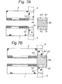
- the arrangement is such that, when the holder 26 is in the attitude shown by the dot-and-dash line, as depicted in Fig. 4, pin fittings intended for a pin 43 and pin box 44 (illustrated in Fig. 7(A)) are introduced from the supply shute 28 into these apertures 41, 42, the holder 26 then being returned to the attitude indicated by the solid lines shown.in Fig. 4.
- the pin fittings will receive the respective core portions 45, 46 thereof (see Figs. 6, 7A and 7B).
- the holding member 36 is formed to include a stopper portion 47 which functions to prevent a pin fitting 43 or 44, located in the aperture 41, from moving along with the respective core portion 45 or 46.
- a die 48 of the lower die device 27 is raised by a driving device, not shown, for pushing the pin fitting holding member 36 upwards.
- the pin fitting holding member 36 is thereby raised along with the holder case 33 for pressing and deforming the pin fittings 43, 44 to secure them onto the core portions 45, 46.
- the die 48 is lowered, followed by actuating a fluid cylinder 49 provided on the base block 29, whereby the cylinder rod 51 presses against the holding member 36 to displace the latter downwardly.
- the pin fitting holding apertures 41, 42 are enlarged to enable the pin fittings 43, 44.to be moved over the stopper 47 with movement of the grippers 3, 4.
- the driving motor 21 used should be capable of developing an accurately adjustable maximum torque.
- the grippers 3, 4 are prevented from undergoing further movement when they have reached a position at which the resistance offered to the grippers 3, 4 by the first elements 52, 53, which abut against the ends of the pin fittings 43, 44, attains a value corresponding to the maximum motor torque.
- a stringer is obtained in which the relative position between the fastener element row and the pin fitting is always constant, thus resulting in a completed slide fastener which is smoothly interlockable.
- Fig. 8 shows a modification of the above-described embodiment. Those portions not described herein are the same as those of the preceding embodiment.
- a gripper 103 is not secured directly to the belt 24, and a driving member 105 is mounted to the belt by a screw 104.
- the driving member and the gripper 103 are connected to each other in a manner to permit relative displacement therebetween in the direction of advance. More particularly, a rod 107 is secured to the slide base 106 of the gripper parallel to the direction of advance thereof, and the driving member 105 is slidably mounted on the rod.
- a compression spring 108 is provided between the slide base 106 and the driving member 105.
- the belt 24 moves intermittently in such a manner that the driving member 105 is stopped at a predetermined position.
- This position is one at which, after movement of the gripper 103 is impeded by the abutting contact between the first element of the stringer and a pin fitting, the driving member 105 undergoes further movement so that the spring 108 will apply a compressive force to the gripper 103, the force acting to the right in the drawing.
- the pressing force which the first element of the stringer applies to the end portion of the pin fitting is variable owing to, say, an error in the positioning of the driving member.105 or fluctuation in the position of the pin fitting in the pin fitting holder, changes in the pressing force caused by minute changes in position are extremely small, so that the stringer core portion can be positioned with the first element being pressed against the pin fitting with a substantially constant force, thus providing a stringer wherein the position of an element row relative to a pin fitting is constant at all times.
Landscapes
- Slide Fasteners (AREA)
- Discharge By Other Means (AREA)
Applications Claiming Priority (2)
| Application Number | Priority Date | Filing Date | Title |
|---|---|---|---|
| JP57120180A JPS5911806A (ja) | 1982-07-10 | 1982-07-10 | 開離嵌挿具付スライドファスナに棒金具を取付ける装置 |
| JP120180/82 | 1982-07-10 |
Publications (2)
| Publication Number | Publication Date |
|---|---|
| EP0099064A1 true EP0099064A1 (de) | 1984-01-25 |
| EP0099064B1 EP0099064B1 (de) | 1985-11-13 |
Family
ID=14779892
Family Applications (1)
| Application Number | Title | Priority Date | Filing Date |
|---|---|---|---|
| EP83106618A Expired EP0099064B1 (de) | 1982-07-10 | 1983-07-06 | Verfahren und Vorrichtung für die Befestigung von Endstopteilen an einem teilbaren Reissverschluss |
Country Status (14)
| Country | Link |
|---|---|
| US (1) | US4494293A (de) |
| EP (1) | EP0099064B1 (de) |
| JP (1) | JPS5911806A (de) |
| KR (1) | KR850000466B1 (de) |
| AU (1) | AU553855B2 (de) |
| BR (1) | BR8303731A (de) |
| CA (1) | CA1203367A (de) |
| DE (2) | DE3361222D1 (de) |
| ES (1) | ES523957A0 (de) |
| GB (1) | GB2123480B (de) |
| HK (1) | HK82988A (de) |
| MY (1) | MY8700788A (de) |
| SG (1) | SG85987G (de) |
| ZA (1) | ZA834763B (de) |
Cited By (7)
| Publication number | Priority date | Publication date | Assignee | Title |
|---|---|---|---|---|
| EP0143447A2 (de) * | 1983-11-26 | 1985-06-05 | Yoshida Kogyo K.K. | Greifvorrichtung |
| EP0160982A2 (de) * | 1984-05-11 | 1985-11-13 | Yoshida Kogyo K.K. | Vorrichtung zum Herstellen von Reissverschlüssen mit zwei Schiebern |
| EP0161647A2 (de) * | 1984-05-18 | 1985-11-21 | Yoshida Kogyo K.K. | Vorrichtung zum Befestigen von Muffenteilen an Reissverschlüssen mit einer aus Kunstharz unteren Teilbarkeitseinrichtung |
| EP0175970A2 (de) * | 1984-09-18 | 1986-04-02 | Yoshida Kogyo K.K. | Verfahren zum Anbringen von unteren trennbaren Endgliederteilen an eine fortlaufende Reissverschlusskette |
| EP0177946A2 (de) * | 1984-10-09 | 1986-04-16 | Yoshida Kogyo K.K. | Verfahren zum Herstellen von trennbaren Reissverschlüssen |
| EP0302362A1 (de) * | 1987-08-04 | 1989-02-08 | Yoshida Kogyo K.K. | Vorrichtung zum Anbringen von Bestandteilen eines Reissverschlusses |
| EP0303215A1 (de) * | 1987-08-11 | 1989-02-15 | Ykk Corporation | Vorrichtung zum Anbringen von oberen Endgliedern an einer Reissverschlusskette |
Families Citing this family (8)
| Publication number | Priority date | Publication date | Assignee | Title |
|---|---|---|---|---|
| DE3402908A1 (de) * | 1984-01-28 | 1985-08-08 | Dr. Karl F. Nägele Feinmaschinen GmbH & Co, 7024 Filderstadt | Verfahren zur montage der teilbarkeitseinrichtung von teilbaren reissverschluessen und montagemaschine dazu |
| JPS6137809U (ja) * | 1984-08-14 | 1986-03-08 | ワイケイケイ株式会社 | フアスナ−チエ−ン送り位置決め装置 |
| JPH0111063Y2 (de) * | 1984-10-05 | 1989-03-30 | ||
| MY101685A (en) * | 1986-10-28 | 1991-12-31 | Yoshida Kogyo Kk | Apparatus for manufacturing slide fasteners |
| JPH0719289Y2 (ja) * | 1987-08-07 | 1995-05-10 | ワイケイケイ株式会社 | スライドフアスナ−用スライダ−の引上げ装置 |
| US4882824A (en) * | 1988-07-05 | 1989-11-28 | Scovill Fasteners Inc. | Apparatus for installing sliders on a gapped slide fastener chain |
| CN105208891B (zh) * | 2014-03-28 | 2018-11-27 | Ykk株式会社 | 拉链的开具安装方法及开具安装装置 |
| CN105283095B (zh) * | 2014-03-28 | 2018-07-31 | Ykk株式会社 | 拉链的打开件安装装置 |
Citations (2)
| Publication number | Priority date | Publication date | Assignee | Title |
|---|---|---|---|---|
| DE2551262B2 (de) * | 1974-11-15 | 1979-09-06 | Yoshida Kogyo K.K., Tokio | Vorrichtung zum Anbringen von Endanschlägen an Reißverschlußbändern |
| GB2041071A (en) * | 1978-12-29 | 1980-09-03 | Yoshida Kogyo Kk | Method of and apparatus for manufacturing slide fasteners |
Family Cites Families (2)
| Publication number | Priority date | Publication date | Assignee | Title |
|---|---|---|---|---|
| US4122594A (en) * | 1977-08-22 | 1978-10-31 | Bruning Bros. Co., Inc. | Method for engaging a slider automatically on a slide fastener chain |
| US4131993A (en) * | 1977-08-22 | 1979-01-02 | Bruning Brothers Company, Inc. | Means for engaging a slider automatically on a slide fastener chain |
-
1982
- 1982-07-10 JP JP57120180A patent/JPS5911806A/ja active Granted
-
1983
- 1983-06-29 AU AU16361/83A patent/AU553855B2/en not_active Ceased
- 1983-06-29 ZA ZA834763A patent/ZA834763B/xx unknown
- 1983-07-06 EP EP83106618A patent/EP0099064B1/de not_active Expired
- 1983-07-06 DE DE8383106618T patent/DE3361222D1/de not_active Expired
- 1983-07-06 DE DE198383106618T patent/DE99064T1/de active Pending
- 1983-07-07 US US06/511,565 patent/US4494293A/en not_active Expired - Lifetime
- 1983-07-08 BR BR8303731A patent/BR8303731A/pt not_active IP Right Cessation
- 1983-07-08 ES ES523957A patent/ES523957A0/es active Granted
- 1983-07-08 CA CA000432097A patent/CA1203367A/en not_active Expired
- 1983-07-09 KR KR1019830003137A patent/KR850000466B1/ko not_active IP Right Cessation
- 1983-07-11 GB GB08318677A patent/GB2123480B/en not_active Expired
-
1987
- 1987-10-12 SG SG859/87A patent/SG85987G/en unknown
- 1987-12-30 MY MY788/87A patent/MY8700788A/xx unknown
-
1988
- 1988-10-13 HK HK829/88A patent/HK82988A/xx not_active IP Right Cessation
Patent Citations (2)
| Publication number | Priority date | Publication date | Assignee | Title |
|---|---|---|---|---|
| DE2551262B2 (de) * | 1974-11-15 | 1979-09-06 | Yoshida Kogyo K.K., Tokio | Vorrichtung zum Anbringen von Endanschlägen an Reißverschlußbändern |
| GB2041071A (en) * | 1978-12-29 | 1980-09-03 | Yoshida Kogyo Kk | Method of and apparatus for manufacturing slide fasteners |
Cited By (14)
| Publication number | Priority date | Publication date | Assignee | Title |
|---|---|---|---|---|
| EP0143447A2 (de) * | 1983-11-26 | 1985-06-05 | Yoshida Kogyo K.K. | Greifvorrichtung |
| EP0143447A3 (en) * | 1983-11-26 | 1987-11-25 | Yoshida Kogyo K.K. | Gripper device |
| EP0160982A3 (en) * | 1984-05-11 | 1988-09-21 | Yoshida Kogyo K.K. | Apparatus for manufacturing bidirectionally openable slide fasteners |
| EP0160982A2 (de) * | 1984-05-11 | 1985-11-13 | Yoshida Kogyo K.K. | Vorrichtung zum Herstellen von Reissverschlüssen mit zwei Schiebern |
| EP0161647A2 (de) * | 1984-05-18 | 1985-11-21 | Yoshida Kogyo K.K. | Vorrichtung zum Befestigen von Muffenteilen an Reissverschlüssen mit einer aus Kunstharz unteren Teilbarkeitseinrichtung |
| EP0161647A3 (en) * | 1984-05-18 | 1988-09-28 | Yoshida Kogyo K.K. | Apparatus for attaching boxes to slide fasteners with separable box and pin of synthetic resin |
| EP0175970A2 (de) * | 1984-09-18 | 1986-04-02 | Yoshida Kogyo K.K. | Verfahren zum Anbringen von unteren trennbaren Endgliederteilen an eine fortlaufende Reissverschlusskette |
| EP0175970A3 (en) * | 1984-09-18 | 1989-07-26 | Yoshida Kogyo K.K. | Method of attaching parts of a separable bottom end assembly to a continuous slide fastener chain |
| EP0177946A2 (de) * | 1984-10-09 | 1986-04-16 | Yoshida Kogyo K.K. | Verfahren zum Herstellen von trennbaren Reissverschlüssen |
| EP0177946A3 (en) * | 1984-10-09 | 1989-07-26 | Yoshida Kogyo K.K. | Method of manufacturing separable slide fasteners |
| EP0302362A1 (de) * | 1987-08-04 | 1989-02-08 | Yoshida Kogyo K.K. | Vorrichtung zum Anbringen von Bestandteilen eines Reissverschlusses |
| US4835845A (en) * | 1987-08-04 | 1989-06-06 | Yoshida Kogyo K. K. | Parts applicator for slide fasteners |
| EP0303215A1 (de) * | 1987-08-11 | 1989-02-15 | Ykk Corporation | Vorrichtung zum Anbringen von oberen Endgliedern an einer Reissverschlusskette |
| US4862585A (en) * | 1987-08-11 | 1989-09-05 | Yoshida Kogyo K. K. | Apparatus for attaching top end stops to slide fastener chain |
Also Published As
| Publication number | Publication date |
|---|---|
| US4494293A (en) | 1985-01-22 |
| SG85987G (en) | 1988-05-20 |
| KR840005330A (ko) | 1984-11-12 |
| BR8303731A (pt) | 1984-02-14 |
| GB2123480A (en) | 1984-02-01 |
| DE99064T1 (de) | 1984-06-20 |
| HK82988A (en) | 1988-10-21 |
| ZA834763B (en) | 1984-03-28 |
| EP0099064B1 (de) | 1985-11-13 |
| GB2123480B (en) | 1985-11-27 |
| GB8318677D0 (en) | 1983-08-10 |
| AU1636183A (en) | 1984-01-12 |
| KR850000466B1 (ko) | 1985-04-08 |
| ES8405262A1 (es) | 1984-06-16 |
| ES523957A0 (es) | 1984-06-16 |
| JPS5911806A (ja) | 1984-01-21 |
| AU553855B2 (en) | 1986-07-31 |
| JPS6340087B2 (de) | 1988-08-09 |
| DE3361222D1 (en) | 1985-12-19 |
| CA1203367A (en) | 1986-04-22 |
| MY8700788A (en) | 1987-12-31 |
Similar Documents
| Publication | Publication Date | Title |
|---|---|---|
| EP0099064B1 (de) | Verfahren und Vorrichtung für die Befestigung von Endstopteilen an einem teilbaren Reissverschluss | |
| US3714698A (en) | Method and machine for assembling slide fasteners of separable type | |
| JPS5941721B2 (ja) | 開離嵌插具付きスライドフアスナ−の製造方法および装置 | |
| US3852869A (en) | Method and apparatus for removing interlocking fastener elements from a slide fastener chain | |
| CA1115469A (en) | Apparatus for injection molding of continuous slide fastener chain | |
| EP0172546B1 (de) | Verfahren und Vorrichtung zur Herstellung gliedfreier Lücken an einem Reissverschlusstragband | |
| EP0160983B1 (de) | Verfahren und Vorrichtung zum Herstellen von Reissverschlüssen mit trennbaren Endgliedern | |
| US4615668A (en) | Apparatus for melt-forming bottom stop of slide fastener chain | |
| US5077884A (en) | Apparatus for manufacturing slide fasteners | |
| JPS5933367B2 (ja) | 開離嵌插具付スライドフアスナ−用間歇フアスナ−チエ−ンの組合せ装置 | |
| EP0068317B1 (de) | Verfahren und Vorrichtung zur Befestigung von Verstärkungsmaterial an Reissverschlussbändern | |
| US4495695A (en) | Apparatus for manufacturing slide fastener having separable end stop | |
| US4580326A (en) | Method and apparatus for automatically threading separable slide fastener stringers through sliders | |
| US3671347A (en) | Method and apparatus for attaching a reinforcing material to a slide fastener chain | |
| US4856695A (en) | Method of and apparatus for feeding slide fastener chain with fly strips | |
| EP0292110B1 (de) | Verfahren und Vorrichtung zur Fütterung von Reissverschlussketten mit Hosenleisten | |
| EP0097342B1 (de) | Vorrichtung zum Aufbringen von Schiebern auf ein Reissverschlussband | |
| CA1243823A (en) | Device for positioning slide fastener stringers in fastener finishing apparatus |
Legal Events
| Date | Code | Title | Description |
|---|---|---|---|
| PUAI | Public reference made under article 153(3) epc to a published international application that has entered the european phase |
Free format text: ORIGINAL CODE: 0009012 |
|
| AK | Designated contracting states |
Designated state(s): BE CH DE FR IT LI NL SE |
|
| ITCL | It: translation for ep claims filed |
Representative=s name: JACOBACCI CASETTA & PERANI S.P.A. |
|
| EL | Fr: translation of claims filed | ||
| TCNL | Nl: translation of patent claims filed | ||
| DET | De: translation of patent claims | ||
| 17P | Request for examination filed |
Effective date: 19840509 |
|
| ITF | It: translation for a ep patent filed |
Owner name: JACOBACCI & PERANI S.P.A. |
|
| GRAA | (expected) grant |
Free format text: ORIGINAL CODE: 0009210 |
|
| AK | Designated contracting states |
Designated state(s): BE CH DE FR IT LI NL SE |
|
| REF | Corresponds to: |
Ref document number: 3361222 Country of ref document: DE Date of ref document: 19851219 |
|
| ET | Fr: translation filed | ||
| PLBE | No opposition filed within time limit |
Free format text: ORIGINAL CODE: 0009261 |
|
| STAA | Information on the status of an ep patent application or granted ep patent |
Free format text: STATUS: NO OPPOSITION FILED WITHIN TIME LIMIT |
|
| 26N | No opposition filed | ||
| ITTA | It: last paid annual fee | ||
| PGFP | Annual fee paid to national office [announced via postgrant information from national office to epo] |
Ref country code: SE Payment date: 19940411 Year of fee payment: 12 |
|
| PGFP | Annual fee paid to national office [announced via postgrant information from national office to epo] |
Ref country code: BE Payment date: 19940415 Year of fee payment: 12 |
|
| PGFP | Annual fee paid to national office [announced via postgrant information from national office to epo] |
Ref country code: CH Payment date: 19940712 Year of fee payment: 12 |
|
| PGFP | Annual fee paid to national office [announced via postgrant information from national office to epo] |
Ref country code: NL Payment date: 19940731 Year of fee payment: 12 |
|
| ITPR | It: changes in ownership of a european patent |
Owner name: CAMBIO RAGIONE SOCIALE;YKK CORPORATION |
|
| REG | Reference to a national code |
Ref country code: FR Ref legal event code: CD |
|
| EAL | Se: european patent in force in sweden |
Ref document number: 83106618.8 |
|
| PG25 | Lapsed in a contracting state [announced via postgrant information from national office to epo] |
Ref country code: SE Effective date: 19950707 |
|
| PG25 | Lapsed in a contracting state [announced via postgrant information from national office to epo] |
Ref country code: LI Effective date: 19950731 Ref country code: CH Effective date: 19950731 Ref country code: BE Effective date: 19950731 |
|
| BERE | Be: lapsed |
Owner name: YOSHIDA KOGYO K.K. Effective date: 19950731 |
|
| PG25 | Lapsed in a contracting state [announced via postgrant information from national office to epo] |
Ref country code: NL Effective date: 19960201 |
|
| REG | Reference to a national code |
Ref country code: CH Ref legal event code: PL |
|
| NLV4 | Nl: lapsed or anulled due to non-payment of the annual fee |
Effective date: 19960201 |
|
| EUG | Se: european patent has lapsed |
Ref document number: 83106618.8 |
|
| PGFP | Annual fee paid to national office [announced via postgrant information from national office to epo] |
Ref country code: FR Payment date: 20020709 Year of fee payment: 20 |
|
| PGFP | Annual fee paid to national office [announced via postgrant information from national office to epo] |
Ref country code: DE Payment date: 20020710 Year of fee payment: 20 |