EP0098763B1 - Verfahren und Einrichtungen der visuellen Telekommunikation, insbesondere für die Verwendung durch Schwerhörige - Google Patents
Verfahren und Einrichtungen der visuellen Telekommunikation, insbesondere für die Verwendung durch Schwerhörige Download PDFInfo
- Publication number
- EP0098763B1 EP0098763B1 EP83401201A EP83401201A EP0098763B1 EP 0098763 B1 EP0098763 B1 EP 0098763B1 EP 83401201 A EP83401201 A EP 83401201A EP 83401201 A EP83401201 A EP 83401201A EP 0098763 B1 EP0098763 B1 EP 0098763B1
- Authority
- EP
- European Patent Office
- Prior art keywords
- image
- signals
- information
- sequence
- point
- Prior art date
- Legal status (The legal status is an assumption and is not a legal conclusion. Google has not performed a legal analysis and makes no representation as to the accuracy of the status listed.)
- Expired
Links
Images

Classifications
-
- G—PHYSICS
- G09—EDUCATION; CRYPTOGRAPHY; DISPLAY; ADVERTISING; SEALS
- G09B—EDUCATIONAL OR DEMONSTRATION APPLIANCES; APPLIANCES FOR TEACHING, OR COMMUNICATING WITH, THE BLIND, DEAF OR MUTE; MODELS; PLANETARIA; GLOBES; MAPS; DIAGRAMS
- G09B21/00—Teaching, or communicating with, the blind, deaf or mute
- G09B21/009—Teaching or communicating with deaf persons
-
- G—PHYSICS
- G09—EDUCATION; CRYPTOGRAPHY; DISPLAY; ADVERTISING; SEALS
- G09B—EDUCATIONAL OR DEMONSTRATION APPLIANCES; APPLIANCES FOR TEACHING, OR COMMUNICATING WITH, THE BLIND, DEAF OR MUTE; MODELS; PLANETARIA; GLOBES; MAPS; DIAGRAMS
- G09B21/00—Teaching, or communicating with, the blind, deaf or mute
- G09B21/06—Devices for teaching lip-reading
Definitions
- the invention relates to telecommunications, and in particular telecommunications by telephone or telematic lines. It relates more particularly to the transmission of images on such links, it being understood that these telephone links are not limited to cables or lines of the electrical type but also include all means of connection of the radio type, with optical fibers, etc.
- telephone lines have been developed, and installed in the form of networks, for the transmission of voice communications. More recently, they have found application to the transmission of digital information, in particular through the use of modulators-demodulators known under the name of MODEM.
- Such telephone links are characterized by performances well suited to the transmission of analog signals at frequencies not exceeding about 4 kHz. When applied to the transmission of digital signals, they generally allow transmission rates up to a maximum of 4800 baud. These performances limit the volume of information which can be transmitted in a determined time interval.
- the telephone lines are well suited to the transmission of human speech or computer messages in the form of binary signals at relatively low rates, they are not suitable for the real-time transmission of images capable of evolve rapidly over time.
- the transmission of an image indeed requires the transfer of a relatively considerable volume of information compared to that of a voice message.
- the image must be divided into quasi-punctual areas which are all the smaller the higher the definition with which one seeks to carry out the transmission.
- a signal representing the relative level of illumination of this zone must be produced. All the signals must then be generally transmitted in series in the form of a sequence. Each sequence corresponds to an image and the signal level at a given instant in this sequence corresponds to the illumination of a corresponding point of the transmitted image.
- the sequence obtained for the image is then subjected to a coding process making it possible to compress the information contained in this sequence with a view to its transmission on a telematic line at a rate of approximately 9600 bits per second.
- the quality of the images obtained by this process is relatively poor, even for a renewal rate limited to a few images per second only. This technique is therefore not suitable for the real-time retransmission of scenes in which a movement must be produced with a certain precision.
- the object of the present invention is to provide a method and a device for the real-time transmission of time-varying visual information using a telephone line or a telematic line of equivalent performance with regard to its speed. . It particularly targets the transmission of information corresponding to movements of the human body, for example gestures or lip movements.
- an application of the invention consists in providing a telecommunications system for people who are deaf and who are able to communicate with each other by sign language or to read or understand the words of a person. person by reading the movement of his lips.
- a picture is taken; for each captured image, the information corresponding to each point of the image is converted into binary signals; the binary signals thus obtained are coded and transmitted to a point on the network; these signals are collected at another point in the network in order to visualize the corresponding image.
- the characteristic contour signals are detected in the captured image. This process can be implemented in several ways. One can for example only transmit variations of contours. You can also periodically transmit a fraction of the contour image, or a visual text. helping for example in the identification of the correspondent.
- the implementation of this method is carried out thanks to a device capable of developing in real time electrical signals representative of visual information, comprising a camera, means for binarizing the signals corresponding to each point of the image in a sequence , and means for coding the signal sequences developed.
- the device according to the invention is characterized by the existence between the camera and the coding means of a device for extracting contours sensitive to variations in the level of illumination of neighboring points inside each image.
- This device can also have different specific characteristics. It may include means of selection and filtering, in particular isolated points. It can include a memory, intended to allow the evaluation of the variation of the contours, or sampling means.
- the invention also includes a device-receiver of signals representative of visual information.
- This device comprises a device for decoding the sequences of signals received on the line, said decoding device supplying an image-by-image display device.
- This receiver device is constructed symmetrically with the transmitter device. It can include a memory and a device for reconstituting the current image. Possibly, several images can be kept in memory.
- a transmission system that can be used using telephone lines or telematic lines of equivalent speed consisting of a transmitter device, a receiver device, both having the characteristics that we have just defined, connected to an interface allowing their connection.
- the image transmission devices by telephone have, in addition to the advantage of allowing the interlocutors to see themselves, that of showing or designating by gestures. It is therefore an improvement in the quality of communication which is carried out essentially verbally. They can in principle allow communication with a person who may be affected by total deafness but is able to read the movements of the lips of one of his interlocutors or between two deaf-mutes who communicate by sign language.
- the videophone type device since the videophone type device only spreads very slowly due to the very high volume of information that it is necessary to transmit and the correlative complexity of the transmission networks to be installed, the possibilities of communication to distance for people with hearing loss is in practice very limited.
- Ordinary telephone lines have a transmission rate of approximately 4800 baud. In the ordinary conditions of transmission of the image of a subject such as the head of a person or his bust and his upper limbs by methods of the television type, such a rate is entirely insufficient.
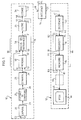
- An example of a station for transmitting and receiving visual information such as the movements of the human body according to the invention comprises (FIG. 1) a transmission sub-assembly 10 and a reception sub-assembly 12 which are all two connected by an interface 14, or a conventional MODEM (modulator-demodulator) device, to a telephone or telematic line 15.
- a transmission sub-assembly 10 and a reception sub-assembly 12 which are all two connected by an interface 14, or a conventional MODEM (modulator-demodulator) device, to a telephone or telematic line 15.
- the transmission sub-assembly comprises a camera 20 provided with a lens 22 suitable for capturing the image of the subject. It is mounted for this purpose on a support not shown so as to obtain a framed image of a subject installed opposite the transceiver station 10, 12.
- This camera 20 is an electronic camera suitable for transforming each of the images of the subject or of the scene to be transmitted formed on its screen in a sequence of electronic signals appearing at its output 23. The signals 23 are exploited by a device for extracting contours 25.
- This device which can be of a known type which will be discussed below, with the property of transforming the signals of each sequence, which are each representative of the level of illumination (halftone image) of each point of the image, into signals to only two levels (corresponding for example to black and white tones), the black tone signals essentially corresponding to points delimiting one or more contours in the image to be transmitted.
- the signals appearing at the output 26 of this device in the form of a sequence therefore represent a sort of cartoon at the rate of, for example, twelve images per second. The data carried by these signals are then compressed before being transmitted to the interface 14.
- Data compression is carried out by a series of juxtaposed modules comprising a sampler 28, by means of which a division by a predetermined factor of the total volume of information of each sequence is obtained, and a movement information extractor 30, at the output 31 of which only appear signals corresponding to points having undergone a modification of their level of illumination between two images of successive contours.
- These signals are transmitted to a filtering device 34, aimed in particular at eliminating the isolated points, at the output of which is an encoder 36 performing a new compression of the data as a function of an analysis of their structure using a set of predetermined coding rules.
- the output 37 of the encoder 36 is connected to the transmission input 38 of the interface 14.
- the output 39 of this interface is connected to an input 41 of a decoding device 40 operating according to the same rules as those of the device 36 to restore to its output 42 a sequence of electrical signals corresponding to a cartoon of the type produced by a transmission device such as 10 at another end of the line 15.
- the signals 42 after processing in an image information reproduction device 44, are transmitted to the input 45 of a display device 46 which performs the visual presentation image by image at the desired rate of the information transmitted on line 15.
- a camera of the type comprising a matrix of photosensitive elements of the charge transfer type of 256 ⁇ 256 elements which are currently available at present.
- the choice of this type of camera is not limiting and other opto-electronic conversion devices can be implemented.
- An advantage of this type of camera is that it does not require a high voltage power supply.
- Each photosensitive element of the camera produces an analog signal, the level of which is proportional to the illumination received by this point.
- These levels of illumination of the set of points of an image are read sequentially and can be digitized by an analog-digital converter so as to produce at output 23 of the camera, for each image, a sequence of digital signals (256 x 256) of six bits each. The position of each of these words in the sequence corresponds to the position of the point in the corresponding image.
- the contour extraction device 25 is produced, without this precision constituting a limitation, for example according to the technique described in the French patent published under No. 2163 815 of July 2, 1973 in the names of NADLER, ADAMOFF and OISEL.
- Another embodiment of a contour extraction device is also found in European Patent No. 55,965 which easily allows the transformation of the image of a natural scene into a contour image.
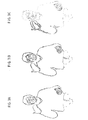
- the result lies in obtaining dark lines on a white background for each image, these lines essentially corresponding to the delimitations of certain parts of the natural image with respect to to the rest of it as shown for example in fig. 2A.
- This device for extracting contours achieves a binarization of the image in the sense that each point of the image is represented in the sequence at output 26 by a binary signal of value 0 or 1 depending on whether the level of illumination of the outline image is white or black.
- the edge extraction devices are characterized in that they are sensitive, in the sequence of signals from the output 23 of the camera 20, to differences in the level of illumination between neighboring points inside each image, that is to say between words corresponding to groups of neighboring points in the image.
- binarization devices of the clipping type in which a signal characteristic of the illumination of a point is converted into a binary value 0 or 1 depending on whether the corresponding illumination level exceeds a threshold, that this threshold is moreover fixed or variable according to other criteria.
- the sampler 28 is a simple image reducer.
- the electrical image at the output 23 of the camera 20 is divided into "lines" each corresponding to the scanning of a line of the matrix of photoelements. In the corresponding electrical signal, each of these lines is separated by an interval symbol between lines.
- the sampler 28 therefore makes a selection of a point out of two or a point out of three (one bit out of two or one bit out of three) among the signals of each line and of a line out of two or of a line out of three in the succession of lines corresponding to the height of the image scanned on the surface of the camera screen 20.
- the lines which correspond in the image are connected by arrows 9 initial and in the reduced image. The analogous compression carried out on the points of these lines is clear from the drawing.
- This sampling can be carried out by conventional means, for example bit counters and line down counters or using a suitably programmed microprocessor.
- FIG. 2A The result of a reduction by a factor of four in the area of an image (FIG. 2A), as it could be represented on the basis of signals from the contour extraction device 25, is shown in FIG. 2B.
- the black and white squares correspond to bits of level 1 and 0 respectively in the sequence of signals of each line, the lines succeeding each other for example from top to bottom in the display which is provided in FIGS 2A and 2B.
- fig. 2C the result of the reduction was represented by a factor of 9 (one point in three for each line and one line in three).
- the compression of the data started by the sampler 28 is continued by a series of data compression steps aimed at obtaining a factor of approximately 20 between the flow at the output of the sampler 28 and the flow at the input 38 of the interface 14.
- the movement information extractor 30 can comprise a memory 50 capable of storing each of the sequences of contour images at the output 29 of the sampler 28 and transmitted on its input 51 by a suitable addressing device.
- the output 52 of the memory 50 is connected to an input 55 of a difference computer 56, the other input 57 of which is directly connected to the output 29 of the sampler 28.
- a sequence of signals corresponding to a contour image these are compared point by point in the difference calculator 56 with the signals of the points of the corresponding image stored in memory.
- the memory is read in at the corresponding rate to display on its output 52 the sequence of signals corresponding to the previous image.
- At the output 31 of the computer 56 appears a sequence of signals representative of the only differences between the two signal trains on the inputs 55 and 57 of the computer 56 (OR EXCLUSIVE function).
- a signal of level 1 appears at the corresponding instant in the sequence of output 31.
- a signal 1 appears at the output 31.
- the addressing device in writing of the memory 50 by the input 51 is provided to write this memory with a slight delay compared to its reading so that the successive points of the current contour image are written immediately after the reading of the corresponding points of the previous image (addressing of a RAM in Read Modified Write mode.
- control and operation of the device 30 can be carried out under the control of suitably programmed microprocessors or using integrated circuits of the current type, according to techniques well known in the art.
- the sequence of output signals 31 comprises information of two types: on the one hand, the signals corresponding to clear displacements of certain parts of the contour between two successive images. These signals constitute the information to be transmitted. On the other hand, it includes numerous signals corresponding to "isolated points" due to small inevitable contrast variations in a system using a camera such as 20.
- FIG. 3C there is shown, in addition to the position variations corresponding to frank movements, such isolated points.
- the frank variations of contours mainly affect the arms and hands.
- there is a high concentration of "isolated” spots in the face results from the mobility of expression of the face of a person speaking. This mobility itself constitutes a significant element of the communication by signs and of course an essential element of the communication of the movement of the lips for the lip reading.
- the filter 34 therefore has a double function: on the one hand, it eliminates the isolated points in the areas where the density of these points is relatively low. On the other hand, it keeps these points where they are present in high concentration, in practice in the facial area.
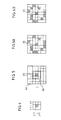
- the points isolated by the filter are detected as illustrated in fig. 4 using a window function.
- the window represents values of an image variable in a neighborhood around each point of interest.
- X be the property of being a point of difference, that is to say corresponding to the passage of a signal 1 to 0 or of a signal 0 to 1 in the sequence of signals 31 , as just indicated above; we can define by X i , the property of being an isolated point of difference, corresponding to the configuration of fig. 4 or the value of X is different for the point of coordinates i, j from that it has for all the points surrounding it in the window considered.
- Boolean algebra we can write: where the function X indicates the absence of the property, according to the usual notation.
- all the signals transmitted to the input of the filter 34 can be subjected to a processing of the type which has just been defined, for example using a storage and a selective interrogation of the signals thus stored. depending on the defined window, the assembly being carried out under the control of a microcircuit or a suitably programmed microprocessor.
- the device analyzes the density of these points on the entire image to reject the only isolated points which correspond to areas where their density is less than a predetermined threshold. This is done by considering a larger analysis window as shown in FIG. 5, comprising a matrix of 7 x 7 elements. This window is scanned only for isolated difference points already detected in a window such as 60 identical to that of FIG. 4. This window 60 is located in the center of the window 62 in FIG. 5 and only the 40 points of window 62 which are not included in window 60 are analyzed in terms of density.
- the density calculation is carried out by counting the number of difference points among the 40 points considered, followed by a test. If, for example, a threshold of 30% is used, the isolated point 65 will not be retained as long as there are less than 12 points of difference of the same kind in the window of 40 points tested. This will be the case in the example of FIG. 6A. If, on the contrary, the number of isolated points in the zone tested is equal to or greater than 12 (case of fig. 6B), the isolated point 65 will be retained and the corresponding signal transmitted to the output 57 of the filter 34 in the direction of input 58 of encoder 36.
- the isolated point detection function X is is applied successively to all the difference points of the image.
- the density threshold function is applied only to isolated points of difference.
- the device 36 performs a coding of the sequence of signals appearing on its input 58 for each image.
- There are different methods of coding black and white images making it possible to compress the sequential information on the input 58 by producing series of digital words at the output 37 of transmission on the line 15 by the interface 14.
- a typical method so-called "range” coding consists in producing a code characteristic of each white-black transition or 0, 1 in the signal sequence at input 58, followed by an indication of a black-white transition code immediately next, with the indication of the number of points between the appearance of these two transitions.
- Other coding systems allowing even more efficient compression of the data are known such as for example the so-called block (quad-tree) coding methods. A certain number of such coding methods are described for example in the July 1980 issue of the journal "Proceedings of The IEEE" devoted to the coding of graphic images.
- the signal sequences appearing at the output 39 of the interface 14 correspond to sequences coming from an encoder 36 of a similar apparatus in another station connected to the telephone transmission network to which the line belongs. 15. They are decoded by the decoder 40 as a function of a code opposite to the code used in transmission. If the signals at output 42 correspond to points of difference between consecutive images, they are applied to an input 75 of an image reconstruction device 76 inside the restorer 44.
- a memory 78 has an input 77 connected at the output 79 of the reconstruction device 76. The output 81 of this memory is connected to the input 45 of this display device which can, for example, consist of a cathode ray tube of the type used for computer terminals.
- the memory 78 is not limited to the storage of a single image. It has the capacity to memorize several successful images complete sives suitable for following one another at output 81 for supplying the display device. It notably includes a memory area directly addressable from input 77 for the reconstruction of each image being received.
- This reconstruction can be carried out symmetrically with the decomposition practiced by the memory extractor 30.
- the reconstructor 76 receives, on an input 82, signals from an output 83 of memory 78 and corresponding to the image previously received and reconstructed.
- the signals on the inputs 75 and 82 of the reconstruction device 76 are admitted in synchronism so as to constitute point by point a complete contour image, each point of the previous image being updated by the corresponding information brought to the input 75.
- the sequence of reconstructed images 79 is then stored in memory 78.
- the image thus reconstructed would not correspond to the image in memory 50 of the transmitting device if care had not been taken, for each isolated point deleted during transmission, to invert the corresponding information in this memory 50.
- the transmission data compression methods which have been mentioned above and, in particular, the method implemented by the encoder 36, introduce a variable delay in the transmission of the image.
- the decoding in the decoder 40 and the reconstruction by the rendering device 44 which require both the knowledge of a complete image and the reception of information corresponding to the current image, introduce a certain offset in the time between the start of the reception of information at the output 39 of the interface and the appearance of a complete image on the display device 46.
- the storage of digital information corresponding to several images in the memory 78 makes it possible to standardize the bit rate of the images transmitted by output 81 to the display device despite the transmission variations mentioned above. It thus succeeds in synchronizing or tuning the frame display rate to the device 46 with the frame rate of the camera 20, and this despite expansions or compressions in time of the transmission of the image sequences along the chain that separates them.
- a certain delay exists between the establishment of the communication between a transmitter and a receiver and the appearance of a complete image. on display 46.
- This timeout can be furnished by information presented in the form of an alphanumeric text and which may correspond, for example, to the name of the caller or to a code belonging to him.
- the called party can receive in advance certain information relating to the visual communication about to be established.
- there is a device for permanently resetting the image displayed during transmission Indeed, the inevitable presence of transmission errors or parasites on the line could have the effect of a progressive deterioration of the reconstructed image.
- each image viewed directly from information coming from the contour extraction device 25 or from the sampler 28, by a line not shown.
- This information which can for example correspond to 1% of the contour image sequence, or to one line per image, is transmitted directly on the interface 38 in place of the compressed and coded portion of the corresponding sequence to be used. downstream of the decoder 40. On arrival, they are also brought directly to the input of the display 45.
- the information announcing the start and the end of the clear signals allows the setting of this information within the sequence corresponding to each image. This setting is modified from image to image so as to update the entire image displayed every hundred sequences if the update information corresponds to 1% of the contour image transmitted.
- a device 90 for image enhancement capable of smoothing between the points, improving the continuity of the contour lines and reducing the effects of jerks points which undergo a position variation between one image and the next.
- image enhancement enhancement
- the invention applies to the transmission in real time over ordinary telephone or telematic lines of any other phenomenon requiring a rate of transmission of visual information similar to that of the movements of the human body or a lower rate.
- it is useful wherever information can be effectively transmitted in the form of drawings as opposed to halftone images. It thereby finds even a possible application to the constitution and transmission of cartoons and also makes it possible to appreciably improve the video-conference techniques mentioned above.
- the invention is moreover not limited to the transmission of visual information at a distance and that it can be used, for example, to carry out digital storage at low speed for the purpose of broadcasting or deferred restitution of information.
Claims (19)
Applications Claiming Priority (2)
| Application Number | Priority Date | Filing Date | Title |
|---|---|---|---|
| FR8210759A FR2529044B1 (fr) | 1982-06-18 | 1982-06-18 | Procedes et dispositifs de telecommunications visuelles, notamment a l'usage des sourds |
| FR8210759 | 1982-06-18 |
Publications (2)
| Publication Number | Publication Date |
|---|---|
| EP0098763A1 EP0098763A1 (de) | 1984-01-18 |
| EP0098763B1 true EP0098763B1 (de) | 1987-03-11 |
Family
ID=9275190
Family Applications (1)
| Application Number | Title | Priority Date | Filing Date |
|---|---|---|---|
| EP83401201A Expired EP0098763B1 (de) | 1982-06-18 | 1983-06-10 | Verfahren und Einrichtungen der visuellen Telekommunikation, insbesondere für die Verwendung durch Schwerhörige |
Country Status (4)
| Country | Link |
|---|---|
| US (1) | US4546383A (de) |
| EP (1) | EP0098763B1 (de) |
| DE (1) | DE3370267D1 (de) |
| FR (1) | FR2529044B1 (de) |
Families Citing this family (57)
| Publication number | Priority date | Publication date | Assignee | Title |
|---|---|---|---|---|
| JPS61217879A (ja) * | 1985-03-25 | 1986-09-27 | Matsushita Electric Works Ltd | 画像照合システム |
| US4975960A (en) * | 1985-06-03 | 1990-12-04 | Petajan Eric D | Electronic facial tracking and detection system and method and apparatus for automated speech recognition |
| JPS61283967A (ja) * | 1985-06-10 | 1986-12-13 | Toshiba Corp | 画像記録再生装置 |
| JPH0766446B2 (ja) * | 1985-11-27 | 1995-07-19 | 株式会社日立製作所 | 移動物体像を抽出する方法 |
| US4665436A (en) * | 1985-12-20 | 1987-05-12 | Osborne Joseph A | Narrow bandwidth signal transmission |
| JPH0740303B2 (ja) * | 1986-07-15 | 1995-05-01 | バール テクノロジイズ インコーポレイティド | テレビジョン信号内に含まれたエッジ情報に応答するモーション検出装置及び方法 |
| US4823194A (en) * | 1986-08-01 | 1989-04-18 | Hitachi, Ltd. | Method for processing gray scale images and an apparatus thereof |
| US4809329A (en) * | 1986-08-29 | 1989-02-28 | National Research Development Corporation | Apparatus for use in conjunction with lipreading by the profoundly deaf |
| DE3877105D1 (de) * | 1987-09-30 | 1993-02-11 | Siemens Ag, 8000 Muenchen, De | |
| US4849807A (en) * | 1988-04-27 | 1989-07-18 | Universal Video Communications Corp. | Method and system for compressing color video feature encoded data |
| US4843466A (en) * | 1988-04-27 | 1989-06-27 | Universal Video Communications Corp. | Method and system for decompressing color video slope encoded data |
| US4816901A (en) * | 1988-04-27 | 1989-03-28 | Universal Video Communications Corp. | Method and system for compressing color video data |
| US4857993A (en) * | 1988-04-27 | 1989-08-15 | Universal Video Communications Corp. | Method and system for decompressing digital color video statistically encoded data |
| US4857991A (en) * | 1988-04-27 | 1989-08-15 | Universal Video Communications Corp. | Method and system for decompressing color video feature encoded data |
| CA1324654C (en) * | 1988-04-27 | 1993-11-23 | Bil (Far East Holdings) Limited | Method and system for compressing color video data |
| US4847677A (en) * | 1988-04-27 | 1989-07-11 | Universal Video Communications Corp. | Video telecommunication system and method for compressing and decompressing digital color video data |
| CA1326898C (en) * | 1988-04-27 | 1994-02-08 | John Music | Method and system for decompressing color video encoded data |
| US4914508A (en) * | 1988-04-27 | 1990-04-03 | Universal Video Communications Corp. | Method and system for compressing and statistically encoding color video data |
| US4878843A (en) * | 1988-06-08 | 1989-11-07 | Kuch Nina J | Process and apparatus for conveying information through motion sequences |
| US4894716A (en) * | 1989-04-20 | 1990-01-16 | Burle Technologies, Inc. | T.V. motion detector with false alarm immunity |
| IT1232109B (it) * | 1989-06-21 | 1992-01-23 | Cselt Centro Studi Lab Telecom | Procedimento e dispositivo di riconoscimento del contorno di immagini in movimento |
| EP0462261A1 (de) * | 1989-12-28 | 1991-12-27 | Massachusetts Institute Of Technology | Bildtelefonsystem |
| US5543939A (en) * | 1989-12-28 | 1996-08-06 | Massachusetts Institute Of Technology | Video telephone systems |
| US5313522A (en) * | 1991-08-23 | 1994-05-17 | Slager Robert P | Apparatus for generating from an audio signal a moving visual lip image from which a speech content of the signal can be comprehended by a lipreader |
| US5887069A (en) * | 1992-03-10 | 1999-03-23 | Hitachi, Ltd. | Sign recognition apparatus and method and sign translation system using same |
| JP3435175B2 (ja) * | 1992-09-03 | 2003-08-11 | 株式会社日立製作所 | 手話学習装置 |
| US5659764A (en) * | 1993-02-25 | 1997-08-19 | Hitachi, Ltd. | Sign language generation apparatus and sign language translation apparatus |
| US5347306A (en) * | 1993-12-17 | 1994-09-13 | Mitsubishi Electric Research Laboratories, Inc. | Animated electronic meeting place |
| US5586171A (en) * | 1994-07-07 | 1996-12-17 | Bell Atlantic Network Services, Inc. | Selection of a voice recognition data base responsive to video data |
| US5506624A (en) * | 1994-07-28 | 1996-04-09 | Silicon Graphics, Inc. | Rotating sample of video images |
| US5572248A (en) * | 1994-09-19 | 1996-11-05 | Teleport Corporation | Teleconferencing method and system for providing face-to-face, non-animated teleconference environment |
| US5982853A (en) | 1995-03-01 | 1999-11-09 | Liebermann; Raanan | Telephone for the deaf and method of using same |
| US6314302B1 (en) * | 1996-12-09 | 2001-11-06 | Siemens Aktiengesellschaft | Method and telecommunication system for supporting multimedia services via an interface and a correspondingly configured subscriber terminal |
| WO1998056209A2 (en) * | 1997-06-02 | 1998-12-10 | Marie Lapalme | Video-assisted apparatus for hearing impaired persons |
| KR100261607B1 (ko) * | 1997-06-30 | 2000-07-15 | 이중구 | 원격 통신이 가능한 디지탈 스틸 카메라 |
| US6348946B1 (en) * | 1997-08-14 | 2002-02-19 | Lockheed Martin Corporation | Video conferencing with video accumulator array VAM memory |
| US5978014A (en) * | 1997-09-19 | 1999-11-02 | 8×8, Inc. | Video TTY device and method for videoconferencing |
| US6116907A (en) * | 1998-01-13 | 2000-09-12 | Sorenson Vision, Inc. | System and method for encoding and retrieving visual signals |
| US7298425B2 (en) * | 1998-03-26 | 2007-11-20 | Micron Technology, Inc. | Method for assisting video compression in a computer system |
| US6987545B1 (en) | 1998-03-26 | 2006-01-17 | Micron Technology, Inc. | Apparatus for assisting video compression in a computer system |
| US6377925B1 (en) | 1999-12-16 | 2002-04-23 | Interactive Solutions, Inc. | Electronic translator for assisting communications |
| US7365766B1 (en) | 2000-08-21 | 2008-04-29 | Marie Lapalme | Video-assisted apparatus for hearing impaired persons |
| US7287009B1 (en) * | 2000-09-14 | 2007-10-23 | Raanan Liebermann | System and a method for carrying out personal and business transactions |
| US6570963B1 (en) * | 2000-10-30 | 2003-05-27 | Sprint Communications Company L.P. | Call center for handling video calls from the hearing impaired |
| US7392287B2 (en) | 2001-03-27 | 2008-06-24 | Hemisphere Ii Investment Lp | Method and apparatus for sharing information using a handheld device |
| DE10127558A1 (de) * | 2001-06-06 | 2002-12-12 | Philips Corp Intellectual Pty | Verfahren zur Verarbeitung einer Text-, Gestik-, Mimik- und/oder Verhaltensbeschreibung mit Überprüfung der Benutzungsberechtigung von Sprach-, Gestik-, Mimik- und/oder Verhaltensprofilen zur Synthese |
| US20020198716A1 (en) * | 2001-06-25 | 2002-12-26 | Kurt Zimmerman | System and method of improved communication |
| US7430283B2 (en) * | 2002-11-06 | 2008-09-30 | Omega Products Corporation | Internet access to telecommunications relay service |
| CN1328908C (zh) * | 2004-11-15 | 2007-07-25 | 北京中星微电子有限公司 | 一种视频通信的方法 |
| US20070052799A1 (en) * | 2005-09-06 | 2007-03-08 | International Business Machines Corporation | System and method for assisting speech development for the hearing-challenged |
| JP4770581B2 (ja) * | 2006-05-17 | 2011-09-14 | ソニー株式会社 | 動画像データ処理装置、ストリーム生成装置、撮像装置、および動画像データ処理方法 |
| CA2565693C (en) * | 2006-10-25 | 2016-01-05 | Universite De Sherbrooke | A method of representing information via sign language |
| US8874445B2 (en) * | 2007-03-30 | 2014-10-28 | Verizon Patent And Licensing Inc. | Apparatus and method for controlling output format of information |
| US20100142683A1 (en) * | 2008-12-09 | 2010-06-10 | Stuart Owen Goldman | Method and apparatus for providing video relay service assisted calls with reduced bandwidth |
| US20100316978A1 (en) * | 2009-06-09 | 2010-12-16 | James David Goode | Mobile, wireless, hands-free visual/verbal trans-language communication system (acronym:V2V XLC System) |
| US9697630B2 (en) | 2014-10-01 | 2017-07-04 | Sony Corporation | Sign language window using picture-in-picture |
| US10412318B1 (en) | 2018-10-30 | 2019-09-10 | Motorola Solutions, Inc. | Systems and methods for processing a video stream during live video sharing |
Family Cites Families (5)
| Publication number | Priority date | Publication date | Assignee | Title |
|---|---|---|---|---|
| US3767847A (en) * | 1971-07-01 | 1973-10-23 | Bell Telephone Labor Inc | Frame-to-frame redundancy reduction system which transmits an intraframe coded signal |
| US4090221A (en) * | 1972-03-13 | 1978-05-16 | Bell Telephone Laboratories, Incorporated | Apparatus for improving video signal-to-noise ratio |
| US3746793A (en) * | 1972-08-09 | 1973-07-17 | Phonics Corp | Telephone communication system for the hearing impaired |
| GB1511647A (en) * | 1974-08-02 | 1978-05-24 | Post Office | Digital television system |
| FR2310044A1 (fr) * | 1975-04-29 | 1976-11-26 | Commissariat Energie Atomique | Procede et dispositif d'isolement de figures dans une image |
-
1982
- 1982-06-18 FR FR8210759A patent/FR2529044B1/fr not_active Expired
-
1983
- 1983-06-10 EP EP83401201A patent/EP0098763B1/de not_active Expired
- 1983-06-10 DE DE8383401201T patent/DE3370267D1/de not_active Expired
- 1983-06-17 US US06/505,309 patent/US4546383A/en not_active Expired - Fee Related
Non-Patent Citations (1)
| Title |
|---|
| CONFERENCE RECORD OF THE INTERNATIONAL CONFERENCE ON COMMUNICATIONS, tenu à Denver, Colorado, 14-18 juin 1981, volume 2 de 4, pages 22.2.1 - 22.2.3. R. H. WALLIS et al.: "Video tele-conferencing at 9600 baud" * |
Also Published As
| Publication number | Publication date |
|---|---|
| FR2529044B1 (fr) | 1986-06-20 |
| EP0098763A1 (de) | 1984-01-18 |
| US4546383A (en) | 1985-10-08 |
| FR2529044A1 (fr) | 1983-12-23 |
| DE3370267D1 (en) | 1987-04-16 |
Similar Documents
| Publication | Publication Date | Title |
|---|---|---|
| EP0098763B1 (de) | Verfahren und Einrichtungen der visuellen Telekommunikation, insbesondere für die Verwendung durch Schwerhörige | |
| EP0266241B1 (de) | Verfahren zur Umwandlung eines originalen Videobildes mit vielen Graupegeln in ein binäres Bild | |
| EP0035436B1 (de) | Ein einem Bild überlagerten Kennstrich-Code verwendendes Fernsehsystem | |
| FR2590099A1 (fr) | Procede pour transmettre une image de haute definition par un canal de communication a bande etroite | |
| FR2751772A1 (fr) | Procede et dispositif fonctionnant en temps reel, pour le reperage et la localisation d'une zone en mouvement relatif dans une scene, ainsi que pour la determination de la vitesse et la direction du deplacement | |
| EP0043298B1 (de) | Fernsehsystem mit hoher Auflösung | |
| KR950030647A (ko) | 화상통신장치 | |
| FR2596175A1 (fr) | Procede et dispositif d'echantillonnage selon des points pseudo-aleatoires en informatique graphique | |
| EP0025748A1 (de) | Vorrichtung zur digitalen Übertragung und bildlichen Darstellung von Graphiken und/oder Zeichen auf einen Bildschirm | |
| EP0416985B1 (de) | Verfahren zum Multiplexieren eines Tonsignals mit einem analogen Videosignal und entsprechendes Verteilungssystem für Standbilder mit Ton | |
| EP0540403A1 (de) | Videoanalyseverfahren für die Montage eines übertragenen oder aufgezeichneten Fernsehprogramms und ihre Verwendung für Nachbearbeitungstechniken, insbesondere in mehrere Sprachen | |
| FR2702914A1 (fr) | Dispositif de codage de suites d'images constituées d'images de nature film et d'images de nature vidéo, et dispositif de décodage correspondant. | |
| EP0332553B1 (de) | Verfahren zur Wiederzuordnung der Wahl eines Unterabtastungsverfahrens nach dem Kriterium einer Datenraten-Reduktion einer Folge von Hilfsdaten, die zur Rekonstruktion eines unterabgetasteten, elektronischen Bildes dienen | |
| FR2589302A1 (fr) | Systeme de thermographie infrarouge a sensibilite amelioree par accumulation progressive des lignes de l'image | |
| EP0063990B1 (de) | Verfahren zur Bildübertragung mit beschränktem Datafluss; Übertragungssystem zur Durchführung dieses Verfahrens | |
| FR2684829A1 (fr) | Methodes de synthese de signaux de texture et de transmission et/ou stockage de tels signaux, ainsi que dispositifs et systemes pour leur mise en óoeuvre. | |
| EP0613605A1 (de) | Verfahren zur Synchronisation der Ablenkung in einem Bildwiedergabeapparat | |
| EP0782327A1 (de) | Verfahren zur Änderung der Auflösung eines digitalen Bildes | |
| EP0520899A1 (de) | Multimedien-Interkommunikationsvorrichtung | |
| EP1168810B1 (de) | Mobiltelefon versehen mit einer Kamera | |
| EP0122653A1 (de) | Verfahren und Einrichtung zum Sortieren von Gegenständen nach ihrer äusseren Erscheinung, insbesondere für eine Farbsortierung von Gegenständen | |
| FR2749116A1 (fr) | Camera a effets speciaux | |
| EP0348321B1 (de) | Verfahren zur Regelung von Hilfsdatenraten für die Rekonstruktion unterabgetasteter, elektronischer Bilder | |
| EP0446334B1 (de) | Vorrichtung zur aufzeichnungsprogrammierung durch erkennung von referenzsignalen | |
| FR2749420A1 (fr) | Procede et dispositif de formation d'images animees d'un interlocuteur |
Legal Events
| Date | Code | Title | Description |
|---|---|---|---|
| PUAI | Public reference made under article 153(3) epc to a published international application that has entered the european phase |
Free format text: ORIGINAL CODE: 0009012 |
|
| AK | Designated contracting states |
Designated state(s): DE GB NL SE |
|
| 17P | Request for examination filed |
Effective date: 19840616 |
|
| GRAA | (expected) grant |
Free format text: ORIGINAL CODE: 0009210 |
|
| AK | Designated contracting states |
Kind code of ref document: B1 Designated state(s): DE GB NL SE |
|
| PG25 | Lapsed in a contracting state [announced via postgrant information from national office to epo] |
Ref country code: SE Effective date: 19870311 Ref country code: NL Effective date: 19870311 |
|
| REF | Corresponds to: |
Ref document number: 3370267 Country of ref document: DE Date of ref document: 19870416 |
|
| NLV1 | Nl: lapsed or annulled due to failure to fulfill the requirements of art. 29p and 29m of the patents act | ||
| PLBE | No opposition filed within time limit |
Free format text: ORIGINAL CODE: 0009261 |
|
| STAA | Information on the status of an ep patent application or granted ep patent |
Free format text: STATUS: NO OPPOSITION FILED WITHIN TIME LIMIT |
|
| 26N | No opposition filed | ||
| PGFP | Annual fee paid to national office [announced via postgrant information from national office to epo] |
Ref country code: GB Payment date: 19930528 Year of fee payment: 11 |
|
| PGFP | Annual fee paid to national office [announced via postgrant information from national office to epo] |
Ref country code: DE Payment date: 19930828 Year of fee payment: 11 |
|
| PG25 | Lapsed in a contracting state [announced via postgrant information from national office to epo] |
Ref country code: GB Effective date: 19940610 |
|
| GBPC | Gb: european patent ceased through non-payment of renewal fee |
Effective date: 19940610 |
|
| PG25 | Lapsed in a contracting state [announced via postgrant information from national office to epo] |
Ref country code: DE Effective date: 19950301 |