EP0098763B1 - Methods and devices for visual telecommunication, especially for use by the deaf - Google Patents
Methods and devices for visual telecommunication, especially for use by the deaf Download PDFInfo
- Publication number
- EP0098763B1 EP0098763B1 EP83401201A EP83401201A EP0098763B1 EP 0098763 B1 EP0098763 B1 EP 0098763B1 EP 83401201 A EP83401201 A EP 83401201A EP 83401201 A EP83401201 A EP 83401201A EP 0098763 B1 EP0098763 B1 EP 0098763B1
- Authority
- EP
- European Patent Office
- Prior art keywords
- image
- signals
- information
- sequence
- point
- Prior art date
- Legal status (The legal status is an assumption and is not a legal conclusion. Google has not performed a legal analysis and makes no representation as to the accuracy of the status listed.)
- Expired
Links
Images

Classifications
-
- G—PHYSICS
- G09—EDUCATION; CRYPTOGRAPHY; DISPLAY; ADVERTISING; SEALS
- G09B—EDUCATIONAL OR DEMONSTRATION APPLIANCES; APPLIANCES FOR TEACHING, OR COMMUNICATING WITH, THE BLIND, DEAF OR MUTE; MODELS; PLANETARIA; GLOBES; MAPS; DIAGRAMS
- G09B21/00—Teaching, or communicating with, the blind, deaf or mute
- G09B21/009—Teaching or communicating with deaf persons
-
- G—PHYSICS
- G09—EDUCATION; CRYPTOGRAPHY; DISPLAY; ADVERTISING; SEALS
- G09B—EDUCATIONAL OR DEMONSTRATION APPLIANCES; APPLIANCES FOR TEACHING, OR COMMUNICATING WITH, THE BLIND, DEAF OR MUTE; MODELS; PLANETARIA; GLOBES; MAPS; DIAGRAMS
- G09B21/00—Teaching, or communicating with, the blind, deaf or mute
- G09B21/06—Devices for teaching lip-reading
Definitions
- the invention relates to telecommunications, and in particular telecommunications by telephone or telematic lines. It relates more particularly to the transmission of images on such links, it being understood that these telephone links are not limited to cables or lines of the electrical type but also include all means of connection of the radio type, with optical fibers, etc.
- telephone lines have been developed, and installed in the form of networks, for the transmission of voice communications. More recently, they have found application to the transmission of digital information, in particular through the use of modulators-demodulators known under the name of MODEM.
- Such telephone links are characterized by performances well suited to the transmission of analog signals at frequencies not exceeding about 4 kHz. When applied to the transmission of digital signals, they generally allow transmission rates up to a maximum of 4800 baud. These performances limit the volume of information which can be transmitted in a determined time interval.
- the telephone lines are well suited to the transmission of human speech or computer messages in the form of binary signals at relatively low rates, they are not suitable for the real-time transmission of images capable of evolve rapidly over time.
- the transmission of an image indeed requires the transfer of a relatively considerable volume of information compared to that of a voice message.
- the image must be divided into quasi-punctual areas which are all the smaller the higher the definition with which one seeks to carry out the transmission.
- a signal representing the relative level of illumination of this zone must be produced. All the signals must then be generally transmitted in series in the form of a sequence. Each sequence corresponds to an image and the signal level at a given instant in this sequence corresponds to the illumination of a corresponding point of the transmitted image.
- the sequence obtained for the image is then subjected to a coding process making it possible to compress the information contained in this sequence with a view to its transmission on a telematic line at a rate of approximately 9600 bits per second.
- the quality of the images obtained by this process is relatively poor, even for a renewal rate limited to a few images per second only. This technique is therefore not suitable for the real-time retransmission of scenes in which a movement must be produced with a certain precision.
- the object of the present invention is to provide a method and a device for the real-time transmission of time-varying visual information using a telephone line or a telematic line of equivalent performance with regard to its speed. . It particularly targets the transmission of information corresponding to movements of the human body, for example gestures or lip movements.
- an application of the invention consists in providing a telecommunications system for people who are deaf and who are able to communicate with each other by sign language or to read or understand the words of a person. person by reading the movement of his lips.
- a picture is taken; for each captured image, the information corresponding to each point of the image is converted into binary signals; the binary signals thus obtained are coded and transmitted to a point on the network; these signals are collected at another point in the network in order to visualize the corresponding image.
- the characteristic contour signals are detected in the captured image. This process can be implemented in several ways. One can for example only transmit variations of contours. You can also periodically transmit a fraction of the contour image, or a visual text. helping for example in the identification of the correspondent.
- the implementation of this method is carried out thanks to a device capable of developing in real time electrical signals representative of visual information, comprising a camera, means for binarizing the signals corresponding to each point of the image in a sequence , and means for coding the signal sequences developed.
- the device according to the invention is characterized by the existence between the camera and the coding means of a device for extracting contours sensitive to variations in the level of illumination of neighboring points inside each image.
- This device can also have different specific characteristics. It may include means of selection and filtering, in particular isolated points. It can include a memory, intended to allow the evaluation of the variation of the contours, or sampling means.
- the invention also includes a device-receiver of signals representative of visual information.
- This device comprises a device for decoding the sequences of signals received on the line, said decoding device supplying an image-by-image display device.
- This receiver device is constructed symmetrically with the transmitter device. It can include a memory and a device for reconstituting the current image. Possibly, several images can be kept in memory.
- a transmission system that can be used using telephone lines or telematic lines of equivalent speed consisting of a transmitter device, a receiver device, both having the characteristics that we have just defined, connected to an interface allowing their connection.
- the image transmission devices by telephone have, in addition to the advantage of allowing the interlocutors to see themselves, that of showing or designating by gestures. It is therefore an improvement in the quality of communication which is carried out essentially verbally. They can in principle allow communication with a person who may be affected by total deafness but is able to read the movements of the lips of one of his interlocutors or between two deaf-mutes who communicate by sign language.
- the videophone type device since the videophone type device only spreads very slowly due to the very high volume of information that it is necessary to transmit and the correlative complexity of the transmission networks to be installed, the possibilities of communication to distance for people with hearing loss is in practice very limited.
- Ordinary telephone lines have a transmission rate of approximately 4800 baud. In the ordinary conditions of transmission of the image of a subject such as the head of a person or his bust and his upper limbs by methods of the television type, such a rate is entirely insufficient.
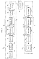
- An example of a station for transmitting and receiving visual information such as the movements of the human body according to the invention comprises (FIG. 1) a transmission sub-assembly 10 and a reception sub-assembly 12 which are all two connected by an interface 14, or a conventional MODEM (modulator-demodulator) device, to a telephone or telematic line 15.
- a transmission sub-assembly 10 and a reception sub-assembly 12 which are all two connected by an interface 14, or a conventional MODEM (modulator-demodulator) device, to a telephone or telematic line 15.
- the transmission sub-assembly comprises a camera 20 provided with a lens 22 suitable for capturing the image of the subject. It is mounted for this purpose on a support not shown so as to obtain a framed image of a subject installed opposite the transceiver station 10, 12.
- This camera 20 is an electronic camera suitable for transforming each of the images of the subject or of the scene to be transmitted formed on its screen in a sequence of electronic signals appearing at its output 23. The signals 23 are exploited by a device for extracting contours 25.
- This device which can be of a known type which will be discussed below, with the property of transforming the signals of each sequence, which are each representative of the level of illumination (halftone image) of each point of the image, into signals to only two levels (corresponding for example to black and white tones), the black tone signals essentially corresponding to points delimiting one or more contours in the image to be transmitted.
- the signals appearing at the output 26 of this device in the form of a sequence therefore represent a sort of cartoon at the rate of, for example, twelve images per second. The data carried by these signals are then compressed before being transmitted to the interface 14.
- Data compression is carried out by a series of juxtaposed modules comprising a sampler 28, by means of which a division by a predetermined factor of the total volume of information of each sequence is obtained, and a movement information extractor 30, at the output 31 of which only appear signals corresponding to points having undergone a modification of their level of illumination between two images of successive contours.
- These signals are transmitted to a filtering device 34, aimed in particular at eliminating the isolated points, at the output of which is an encoder 36 performing a new compression of the data as a function of an analysis of their structure using a set of predetermined coding rules.
- the output 37 of the encoder 36 is connected to the transmission input 38 of the interface 14.
- the output 39 of this interface is connected to an input 41 of a decoding device 40 operating according to the same rules as those of the device 36 to restore to its output 42 a sequence of electrical signals corresponding to a cartoon of the type produced by a transmission device such as 10 at another end of the line 15.
- the signals 42 after processing in an image information reproduction device 44, are transmitted to the input 45 of a display device 46 which performs the visual presentation image by image at the desired rate of the information transmitted on line 15.
- a camera of the type comprising a matrix of photosensitive elements of the charge transfer type of 256 ⁇ 256 elements which are currently available at present.
- the choice of this type of camera is not limiting and other opto-electronic conversion devices can be implemented.
- An advantage of this type of camera is that it does not require a high voltage power supply.
- Each photosensitive element of the camera produces an analog signal, the level of which is proportional to the illumination received by this point.
- These levels of illumination of the set of points of an image are read sequentially and can be digitized by an analog-digital converter so as to produce at output 23 of the camera, for each image, a sequence of digital signals (256 x 256) of six bits each. The position of each of these words in the sequence corresponds to the position of the point in the corresponding image.
- the contour extraction device 25 is produced, without this precision constituting a limitation, for example according to the technique described in the French patent published under No. 2163 815 of July 2, 1973 in the names of NADLER, ADAMOFF and OISEL.
- Another embodiment of a contour extraction device is also found in European Patent No. 55,965 which easily allows the transformation of the image of a natural scene into a contour image.
- the result lies in obtaining dark lines on a white background for each image, these lines essentially corresponding to the delimitations of certain parts of the natural image with respect to to the rest of it as shown for example in fig. 2A.
- This device for extracting contours achieves a binarization of the image in the sense that each point of the image is represented in the sequence at output 26 by a binary signal of value 0 or 1 depending on whether the level of illumination of the outline image is white or black.
- the edge extraction devices are characterized in that they are sensitive, in the sequence of signals from the output 23 of the camera 20, to differences in the level of illumination between neighboring points inside each image, that is to say between words corresponding to groups of neighboring points in the image.
- binarization devices of the clipping type in which a signal characteristic of the illumination of a point is converted into a binary value 0 or 1 depending on whether the corresponding illumination level exceeds a threshold, that this threshold is moreover fixed or variable according to other criteria.
- the sampler 28 is a simple image reducer.
- the electrical image at the output 23 of the camera 20 is divided into "lines" each corresponding to the scanning of a line of the matrix of photoelements. In the corresponding electrical signal, each of these lines is separated by an interval symbol between lines.
- the sampler 28 therefore makes a selection of a point out of two or a point out of three (one bit out of two or one bit out of three) among the signals of each line and of a line out of two or of a line out of three in the succession of lines corresponding to the height of the image scanned on the surface of the camera screen 20.
- the lines which correspond in the image are connected by arrows 9 initial and in the reduced image. The analogous compression carried out on the points of these lines is clear from the drawing.
- This sampling can be carried out by conventional means, for example bit counters and line down counters or using a suitably programmed microprocessor.
- FIG. 2A The result of a reduction by a factor of four in the area of an image (FIG. 2A), as it could be represented on the basis of signals from the contour extraction device 25, is shown in FIG. 2B.
- the black and white squares correspond to bits of level 1 and 0 respectively in the sequence of signals of each line, the lines succeeding each other for example from top to bottom in the display which is provided in FIGS 2A and 2B.
- fig. 2C the result of the reduction was represented by a factor of 9 (one point in three for each line and one line in three).
- the compression of the data started by the sampler 28 is continued by a series of data compression steps aimed at obtaining a factor of approximately 20 between the flow at the output of the sampler 28 and the flow at the input 38 of the interface 14.
- the movement information extractor 30 can comprise a memory 50 capable of storing each of the sequences of contour images at the output 29 of the sampler 28 and transmitted on its input 51 by a suitable addressing device.
- the output 52 of the memory 50 is connected to an input 55 of a difference computer 56, the other input 57 of which is directly connected to the output 29 of the sampler 28.
- a sequence of signals corresponding to a contour image these are compared point by point in the difference calculator 56 with the signals of the points of the corresponding image stored in memory.
- the memory is read in at the corresponding rate to display on its output 52 the sequence of signals corresponding to the previous image.
- At the output 31 of the computer 56 appears a sequence of signals representative of the only differences between the two signal trains on the inputs 55 and 57 of the computer 56 (OR EXCLUSIVE function).
- a signal of level 1 appears at the corresponding instant in the sequence of output 31.
- a signal 1 appears at the output 31.
- the addressing device in writing of the memory 50 by the input 51 is provided to write this memory with a slight delay compared to its reading so that the successive points of the current contour image are written immediately after the reading of the corresponding points of the previous image (addressing of a RAM in Read Modified Write mode.
- control and operation of the device 30 can be carried out under the control of suitably programmed microprocessors or using integrated circuits of the current type, according to techniques well known in the art.
- the sequence of output signals 31 comprises information of two types: on the one hand, the signals corresponding to clear displacements of certain parts of the contour between two successive images. These signals constitute the information to be transmitted. On the other hand, it includes numerous signals corresponding to "isolated points" due to small inevitable contrast variations in a system using a camera such as 20.
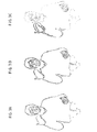
- FIG. 3C there is shown, in addition to the position variations corresponding to frank movements, such isolated points.
- the frank variations of contours mainly affect the arms and hands.
- there is a high concentration of "isolated” spots in the face results from the mobility of expression of the face of a person speaking. This mobility itself constitutes a significant element of the communication by signs and of course an essential element of the communication of the movement of the lips for the lip reading.
- the filter 34 therefore has a double function: on the one hand, it eliminates the isolated points in the areas where the density of these points is relatively low. On the other hand, it keeps these points where they are present in high concentration, in practice in the facial area.
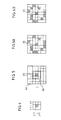
- the points isolated by the filter are detected as illustrated in fig. 4 using a window function.
- the window represents values of an image variable in a neighborhood around each point of interest.
- X be the property of being a point of difference, that is to say corresponding to the passage of a signal 1 to 0 or of a signal 0 to 1 in the sequence of signals 31 , as just indicated above; we can define by X i , the property of being an isolated point of difference, corresponding to the configuration of fig. 4 or the value of X is different for the point of coordinates i, j from that it has for all the points surrounding it in the window considered.
- Boolean algebra we can write: where the function X indicates the absence of the property, according to the usual notation.
- all the signals transmitted to the input of the filter 34 can be subjected to a processing of the type which has just been defined, for example using a storage and a selective interrogation of the signals thus stored. depending on the defined window, the assembly being carried out under the control of a microcircuit or a suitably programmed microprocessor.
- the device analyzes the density of these points on the entire image to reject the only isolated points which correspond to areas where their density is less than a predetermined threshold. This is done by considering a larger analysis window as shown in FIG. 5, comprising a matrix of 7 x 7 elements. This window is scanned only for isolated difference points already detected in a window such as 60 identical to that of FIG. 4. This window 60 is located in the center of the window 62 in FIG. 5 and only the 40 points of window 62 which are not included in window 60 are analyzed in terms of density.
- the density calculation is carried out by counting the number of difference points among the 40 points considered, followed by a test. If, for example, a threshold of 30% is used, the isolated point 65 will not be retained as long as there are less than 12 points of difference of the same kind in the window of 40 points tested. This will be the case in the example of FIG. 6A. If, on the contrary, the number of isolated points in the zone tested is equal to or greater than 12 (case of fig. 6B), the isolated point 65 will be retained and the corresponding signal transmitted to the output 57 of the filter 34 in the direction of input 58 of encoder 36.
- the isolated point detection function X is is applied successively to all the difference points of the image.
- the density threshold function is applied only to isolated points of difference.
- the device 36 performs a coding of the sequence of signals appearing on its input 58 for each image.
- There are different methods of coding black and white images making it possible to compress the sequential information on the input 58 by producing series of digital words at the output 37 of transmission on the line 15 by the interface 14.
- a typical method so-called "range” coding consists in producing a code characteristic of each white-black transition or 0, 1 in the signal sequence at input 58, followed by an indication of a black-white transition code immediately next, with the indication of the number of points between the appearance of these two transitions.
- Other coding systems allowing even more efficient compression of the data are known such as for example the so-called block (quad-tree) coding methods. A certain number of such coding methods are described for example in the July 1980 issue of the journal "Proceedings of The IEEE" devoted to the coding of graphic images.
- the signal sequences appearing at the output 39 of the interface 14 correspond to sequences coming from an encoder 36 of a similar apparatus in another station connected to the telephone transmission network to which the line belongs. 15. They are decoded by the decoder 40 as a function of a code opposite to the code used in transmission. If the signals at output 42 correspond to points of difference between consecutive images, they are applied to an input 75 of an image reconstruction device 76 inside the restorer 44.
- a memory 78 has an input 77 connected at the output 79 of the reconstruction device 76. The output 81 of this memory is connected to the input 45 of this display device which can, for example, consist of a cathode ray tube of the type used for computer terminals.
- the memory 78 is not limited to the storage of a single image. It has the capacity to memorize several successful images complete sives suitable for following one another at output 81 for supplying the display device. It notably includes a memory area directly addressable from input 77 for the reconstruction of each image being received.
- This reconstruction can be carried out symmetrically with the decomposition practiced by the memory extractor 30.
- the reconstructor 76 receives, on an input 82, signals from an output 83 of memory 78 and corresponding to the image previously received and reconstructed.
- the signals on the inputs 75 and 82 of the reconstruction device 76 are admitted in synchronism so as to constitute point by point a complete contour image, each point of the previous image being updated by the corresponding information brought to the input 75.
- the sequence of reconstructed images 79 is then stored in memory 78.
- the image thus reconstructed would not correspond to the image in memory 50 of the transmitting device if care had not been taken, for each isolated point deleted during transmission, to invert the corresponding information in this memory 50.
- the transmission data compression methods which have been mentioned above and, in particular, the method implemented by the encoder 36, introduce a variable delay in the transmission of the image.
- the decoding in the decoder 40 and the reconstruction by the rendering device 44 which require both the knowledge of a complete image and the reception of information corresponding to the current image, introduce a certain offset in the time between the start of the reception of information at the output 39 of the interface and the appearance of a complete image on the display device 46.
- the storage of digital information corresponding to several images in the memory 78 makes it possible to standardize the bit rate of the images transmitted by output 81 to the display device despite the transmission variations mentioned above. It thus succeeds in synchronizing or tuning the frame display rate to the device 46 with the frame rate of the camera 20, and this despite expansions or compressions in time of the transmission of the image sequences along the chain that separates them.
- a certain delay exists between the establishment of the communication between a transmitter and a receiver and the appearance of a complete image. on display 46.
- This timeout can be furnished by information presented in the form of an alphanumeric text and which may correspond, for example, to the name of the caller or to a code belonging to him.
- the called party can receive in advance certain information relating to the visual communication about to be established.
- there is a device for permanently resetting the image displayed during transmission Indeed, the inevitable presence of transmission errors or parasites on the line could have the effect of a progressive deterioration of the reconstructed image.
- each image viewed directly from information coming from the contour extraction device 25 or from the sampler 28, by a line not shown.
- This information which can for example correspond to 1% of the contour image sequence, or to one line per image, is transmitted directly on the interface 38 in place of the compressed and coded portion of the corresponding sequence to be used. downstream of the decoder 40. On arrival, they are also brought directly to the input of the display 45.
- the information announcing the start and the end of the clear signals allows the setting of this information within the sequence corresponding to each image. This setting is modified from image to image so as to update the entire image displayed every hundred sequences if the update information corresponds to 1% of the contour image transmitted.
- a device 90 for image enhancement capable of smoothing between the points, improving the continuity of the contour lines and reducing the effects of jerks points which undergo a position variation between one image and the next.
- image enhancement enhancement
- the invention applies to the transmission in real time over ordinary telephone or telematic lines of any other phenomenon requiring a rate of transmission of visual information similar to that of the movements of the human body or a lower rate.
- it is useful wherever information can be effectively transmitted in the form of drawings as opposed to halftone images. It thereby finds even a possible application to the constitution and transmission of cartoons and also makes it possible to appreciably improve the video-conference techniques mentioned above.
- the invention is moreover not limited to the transmission of visual information at a distance and that it can be used, for example, to carry out digital storage at low speed for the purpose of broadcasting or deferred restitution of information.
Description
L'invention est relative aux télécommunications, et notamment aux télécommunications par lignes téléphoniques ou télématiques. Elle vise plus particulièrement la transmission d'images sur de telles liaisons, étant entendu que ces liaisons téléphoniques ne sont pas limitées aux câbles ou lignes de type électrique mais englobent également tous moyens de liaison de type hertzien, à fibres optiques, etc.The invention relates to telecommunications, and in particular telecommunications by telephone or telematic lines. It relates more particularly to the transmission of images on such links, it being understood that these telephone links are not limited to cables or lines of the electrical type but also include all means of connection of the radio type, with optical fibers, etc.
Traditionnellement, les lignes téléphoniques ont été développées, et installées sous forme de réseaux, pour la transmission de communications vocales. Plus récemment, elles onttrouvé application à la transmission d'informations de type numérique, grâce notamment à l'utilisation de modulateurs-démodulateurs connus sous l'appellation de MODEM. De telles liaisons téléphoniques sont caractérisées par des performances bien adaptées à la transmission de signaux analogiques à des fréquences n'excédant pas environ 4 kHz. Lorsqu'elles sont appliquées à la transmission de signaux numériques, elles autorisent en général des cadences de transmission pouvant atteindre au maximum 4800 bauds. Ces performances limitent le volume des informations qui peuvent être transmises dans un intervalle de temps déterminé.Traditionally, telephone lines have been developed, and installed in the form of networks, for the transmission of voice communications. More recently, they have found application to the transmission of digital information, in particular through the use of modulators-demodulators known under the name of MODEM. Such telephone links are characterized by performances well suited to the transmission of analog signals at frequencies not exceeding about 4 kHz. When applied to the transmission of digital signals, they generally allow transmission rates up to a maximum of 4800 baud. These performances limit the volume of information which can be transmitted in a determined time interval.
Ainsi, si les lignes téléphoniques sont bien adaptées à la transmission de la parole humaine ou de messages informatiques sous la forme de signaux binaires à des cadences relativement peu élevées, elles ne sont pas aptes à la transmission en temps réel d'images susceptibles d'évoluer rapidement dans le temps. La transmission d'une image nécessite en effet le transfert d'un volume d'informations relativement considérable par rapport à celui d'un message vocal. L'image doit être divisée en zones quasi-ponctuelles d'autant plus petites que la définition avec laquelle on cherche à réaliser la transmission est élevée. Pour chacune de ces zones ponctuelles, un signal représentant le niveau d'éclairement relatif de cette zone doit être produit. L'ensemble des signaux doit être alors transmis en général en série sous la forme d'une séquence. Chaque séquence correspond à une image et le niveau du signal à un instant donné de cette séquence correspond à l'éclairement d'un point correspondant de l'image transmise.Thus, if the telephone lines are well suited to the transmission of human speech or computer messages in the form of binary signals at relatively low rates, they are not suitable for the real-time transmission of images capable of evolve rapidly over time. The transmission of an image indeed requires the transfer of a relatively considerable volume of information compared to that of a voice message. The image must be divided into quasi-punctual areas which are all the smaller the higher the definition with which one seeks to carry out the transmission. For each of these point zones, a signal representing the relative level of illumination of this zone must be produced. All the signals must then be generally transmitted in series in the form of a sequence. Each sequence corresponds to an image and the signal level at a given instant in this sequence corresponds to the illumination of a corresponding point of the transmitted image.
La transmission de telles séquences est bien connue dans les systèmes de télévision. Dans ces systèmes, pour la transmission de scènes en mouvement, la cadence de renouvellement des images transmises est relativement élevée. Elle nécessite des liaisons capables de transmettre une bande de fréquence dont la largeur est sans aucune mesure avec celle des liaisons téléphoniques simples.The transmission of such sequences is well known in television systems. In these systems, for the transmission of moving scenes, the renewal rate of the transmitted images is relatively high. It requires links capable of transmitting a frequency band whose width is without any measurement with that of simple telephone links.
On a déjà cherché à améliorer le confort des communications téléphoniques en transmettant l'image des interlocuteurs l'un à l'autre à l'aide d'un tel système désigné en général sous l'appellation de visiophone. Le coût de ces systèmes a entravé leur développement en raison notamment du fait que la puissance de transmission d'informations nécessaire pour obtenir des images de qualité convenable est environ vingt à quarante fois plus élevée que celle d'une ligne téléphonique destinée à la parole seulement.Attempts have already been made to improve the comfort of telephone communications by transmitting the image of the interlocutors to one another using such a system generally designated by the name of videophone. The cost of these systems has hindered their development, due in part to the fact that the information transmission power required to obtain images of suitable quality is approximately twenty to forty times higher than that of a telephone line intended for speech only. .
On a déjà proposé, dans le cas où les images à transmettre sont relativement statiques, des systèmes visant à réduire le débit des informations à transmettre. Dans un tel système, décrit par exemple dans la communication intitulée: Vl-DEO TELECONFERENCING AT 9600 BAUDS par Robert H. Wallis et William K. Pratt parue dans "IEEE Picture Coding Symposium, Montréal 1981", une image d'un sujet à transmettre est produite, par exemple le buste d'un interlocuteur dans une conférence à distance, à l'aide d'une caméra opto-électronique. Les signaux électriques résultants sont soumis à un processus de binarisation, à l'issue duquel chaque point de l'image est représenté par un signal capable de prendre seulement deux valeurs. La séquence obtenue pour l'image est alors soumise à un processus de codage permettant de comprimer l'information contenue dans cette séquence en vue de sa transmission sur une ligne télématique à une cadence d'environ 9600 bits par seconde. La qualité des images obtenues par ce procédé est relativement médiocre, même pour une cadence de renouvellement limitée à quelques images par seconde seulement. Cette technique n'est donc pas adaptée à la retransmission en temps réel de scènes dans lesquelles un mouvement doit être produit avec une certaine précision.We have already proposed, in the case where the images to be transmitted are relatively static, systems aimed at reducing the bit rate of the information to be transmitted. In such a system, described for example in the communication entitled: Vl-DEO TELECONFERENCING AT 9600 BAUDS by Robert H. Wallis and William K. Pratt published in "IEEE Picture Coding Symposium, Montréal 1981", an image of a subject to be transmitted is produced, for example the bust of an interlocutor in a remote conference, using an opto-electronic camera. The resulting electrical signals are subjected to a binarization process, at the end of which each point of the image is represented by a signal capable of taking only two values. The sequence obtained for the image is then subjected to a coding process making it possible to compress the information contained in this sequence with a view to its transmission on a telematic line at a rate of approximately 9600 bits per second. The quality of the images obtained by this process is relatively poor, even for a renewal rate limited to a few images per second only. This technique is therefore not suitable for the real-time retransmission of scenes in which a movement must be produced with a certain precision.
La présente invention a pour but de fournir un procédé et un dispositif de transmission en temps réel d'informations visuelles variables dans le temps à l'aide d'une ligne téléphonique ou d'une ligne télématique de performances équivalentes en ce qui concerne son débit. Elle vise particulièrement la transmission d'information correspondant à des mouvements du corps humain, par exemple à des gestes ou à des mouvements de lèvres. A cet égard, une application de l'invention consiste en la fourniture d'un système de télécommunications pour des personnes atteintes de surdité et qui sont capables de communiquer entre elles par le langage des signes ou de lire ou de comprendre les paroles d'une personne par la lecture du mouvement de ses lèvres.The object of the present invention is to provide a method and a device for the real-time transmission of time-varying visual information using a telephone line or a telematic line of equivalent performance with regard to its speed. . It particularly targets the transmission of information corresponding to movements of the human body, for example gestures or lip movements. In this regard, an application of the invention consists in providing a telecommunications system for people who are deaf and who are able to communicate with each other by sign language or to read or understand the words of a person. person by reading the movement of his lips.
A cet effet, dans le procédé selon l'invention on effectue une prise de vue; pour chaque image saisie, on convertit en signaux binaires les informations correspondant à chaque point de l'image; on code et on transmet les signaux binaires ainsi obtenus en un point du réseau; on recueille ces signaux en un autre point du réseau afin de visualiser l'image correspondante. Selon l'invention, dans chaque séquence de signaux on détecte les signaux caractéristiques de contours dans l'image saisie. Ce procédé peut être mis en oeuvre selon plusieurs modalités. On peut par exemple ne transmettre que des variations de contours. On peut également transmettre périodiquement une fraction de l'image de contours, ou un texte visualisé aidant par exemple à l'identification du correspondant.To this end, in the method according to the invention, a picture is taken; for each captured image, the information corresponding to each point of the image is converted into binary signals; the binary signals thus obtained are coded and transmitted to a point on the network; these signals are collected at another point in the network in order to visualize the corresponding image. According to the invention, in each sequence of signals, the characteristic contour signals are detected in the captured image. This process can be implemented in several ways. One can for example only transmit variations of contours. You can also periodically transmit a fraction of the contour image, or a visual text. helping for example in the identification of the correspondent.
La mise en oeuvre de ce procédé se réalise grâce à un dispositif capable d'élaborer en temps réels des signaux électriques représentatifs d'informations visuelles, comprenant une caméra, des moyens pour binariser les signaux correspondant à chaque point de l'image dans une séquence, et des moyens de codage des séquences de signaux élaborés. Le dispositif selon l'invention se caractérise par l'existence entre la caméra et les moyens de codage d'un dispositif d'extraction de contours sensible à des écarts du niveau d'éclairement de points voisins à l'intérieur de chaque image. Ce dispositif peut présenter en outre différentes caractéristiques particulières. Il peut comporter des moyens de sélection et de filtrage, en particulier des points isolés. Il peut comporter une mémoire, destinée à permettre l'évaluation de la variation des contours, ou des moyens d'échantillonnage.The implementation of this method is carried out thanks to a device capable of developing in real time electrical signals representative of visual information, comprising a camera, means for binarizing the signals corresponding to each point of the image in a sequence , and means for coding the signal sequences developed. The device according to the invention is characterized by the existence between the camera and the coding means of a device for extracting contours sensitive to variations in the level of illumination of neighboring points inside each image. This device can also have different specific characteristics. It may include means of selection and filtering, in particular isolated points. It can include a memory, intended to allow the evaluation of the variation of the contours, or sampling means.
L'invention comporte également un dispositif-récepteur de signaux représentatifs d'informations visuelles. Ce dispositif comprend un dispositif de décodage des séquences de signaux reçus sur la ligne, ledit dispositif de décodage alimentant un dispositif de visualisation image par image. Ce dispositif-récepteur est construit de façon symétrique du dispositif-émetteur. Il peutcom- porterunemémoireetun dispositif de reconstitution de l'image en cours. Eventuellement, plusieurs images pourront être conservées en mémoire.The invention also includes a device-receiver of signals representative of visual information. This device comprises a device for decoding the sequences of signals received on the line, said decoding device supplying an image-by-image display device. This receiver device is constructed symmetrically with the transmitter device. It can include a memory and a device for reconstituting the current image. Possibly, several images can be kept in memory.
Selon l'invention, on dispose également d'un système de transmission pouvant être utilisé à l'aide de lignes téléphoniques ou de lignes télématiques d'un débit équivalent constitué d'un dispositif-émetteur, d'un dispositif-récepteur les deux ayant les caractéristiques que l'on vient de définir, connectés à une interface permettant leur raccordement.According to the invention, there is also a transmission system that can be used using telephone lines or telematic lines of equivalent speed consisting of a transmitter device, a receiver device, both having the characteristics that we have just defined, connected to an interface allowing their connection.
L'invention sera explicitée davantage à l'aide de la description non limitative d'exemples de réalisation qui est donnée ci-après en référence aux dessins annexés, sur lesquels:
- - la fig. 1 est un schéma synoptique d'un dispositif d'émission et de réception propre à être raccordé à une ligne téléphonique;
- - les figs 2A à 2D illustrent les effets d'un dispositif d'échantillonnage qui peut être utilisé selon l'invention;
- - les figs 3A à 3C illustrent les explications relatives à la transformation de l'image du sujet en un dessin animé et à sa transmission;
- - les figs 4 et 5 illustrent des explications relatives au filtrage;
les figs 6A et 6B complètent ces dernières explications.The invention will be explained further with the aid of the non-limiting description of exemplary embodiments which is given below with reference to the appended drawings, in which:
- - fig. 1 is a block diagram of a transmission and reception device suitable for being connected to a telephone line;
- - Figs 2A to 2D illustrate the effects of a sampling device which can be used according to the invention;
- - Figs 3A to 3C illustrate the explanations relating to the transformation of the subject's image into a cartoon and its transmission;
- - Figs 4 and 5 illustrate explanations relating to filtering;
Figs 6A and 6B complete these latter explanations.
Les dispositifs de transmission d'images par liaison téléphonique présentent, outre l'avantage de permettre aux interlocuteurs de se voir, celui de montrer ou désigner par gestes. Il s'agit donc d'une amélioration à la qualité de la communication qui s'effectue de manière essentiellement verbale. Ils peuvent en principe permettre une communication avec une personne qui peut être affectée de surdité totale mais est capable de lire les mouvements des lèvres d'un de ses interlocuteurs ou entre deux sourds-muets qui communiquent par le langage des signes. Cependant, dans la mesure où le dispositif du type visiophone ne se répand que très lentement en raison du volume d'informations très élevées qu'il est nécessaire de transmettre et de la complexité corrélative des réseaux de transmission à installer, les possibilités de communication à distance pour des personnes affectées de surdité sont en pratique très limitées.The image transmission devices by telephone have, in addition to the advantage of allowing the interlocutors to see themselves, that of showing or designating by gestures. It is therefore an improvement in the quality of communication which is carried out essentially verbally. They can in principle allow communication with a person who may be affected by total deafness but is able to read the movements of the lips of one of his interlocutors or between two deaf-mutes who communicate by sign language. However, since the videophone type device only spreads very slowly due to the very high volume of information that it is necessary to transmit and the correlative complexity of the transmission networks to be installed, the possibilities of communication to distance for people with hearing loss is in practice very limited.
Des études qui ont présidé à l'invention ont fait ressortir que la transmission précise du mouvement des lèvres ou des gestes, dans le cas d'une transmission par signes, devait s'effectuer à une cadence d'au moins environ 12 images par seconde. Cette cadence est nécessaire, compte tenu de la rapidité de certains gestes et de la nécessité de conserver un certain confort visuel pour l'observateur en évitant de produire une image trop saccadée.Studies which have governed the invention have shown that the precise transmission of the movement of the lips or of the gestures, in the case of a transmission by signs, must be carried out at a rate of at least approximately 12 images per second. . This cadence is necessary, given the speed of certain gestures and the need to maintain a certain visual comfort for the observer by avoiding producing an image that is too jerky.
Les lignes téléphoniques ordinaires ont un débit de transmission d'environ 4800 bauds. Dans les conditions ordinaires de transmission de l'image d'un sujet telle que la tête d'une personne ou son buste et ses membres supérieurs par des procédés de type télévisuel, une telle cadence est tout à fait insuffisante.Ordinary telephone lines have a transmission rate of approximately 4800 baud. In the ordinary conditions of transmission of the image of a subject such as the head of a person or his bust and his upper limbs by methods of the television type, such a rate is entirely insufficient.
Un exemple de poste d'émission et de réception d'informations visuelles telles que les mouvements du corps humain selon l'invention comprend (fig. 1) un sous-ensemble d'émission 10 et un sous-ensemble de réception 12 qui sont tous deux raccordés par une interface 14, ou un dispositif de MODEM (modulateur-démodulateur) classique, à une ligne téléphonique ou télématique 15.An example of a station for transmitting and receiving visual information such as the movements of the human body according to the invention comprises (FIG. 1) a
Le sous-ensemble d'émission comprend une caméra 20 pourvue d'un objectif 22 propre à effectuer la saisie d'image du sujet. Elle est montée à cet effet sur un support non représenté de façon à permettre l'obtention d'une image cadrée d'un sujet installé face au poste d'émission-réception 10, 12. Cette caméra 20 est une caméra électronique propre à transformer chacune des images du sujet ou de la scène à transmettre formée sur son écran en une séquence de signaux électroniques apparaissant à sa sortie 23. Les signaux 23 sont exploités par un dispositif d'extraction de contours 25. Ce dispositif, qui peut être d'un type connu dont il sera reparlé ci-après, à la propriété de transformer les signaux de chaque séquence, lesquels sont chacun représentatif du niveau d'éclairement (image en demi-teinte) de chaque point de l'image, en des signaux à deux niveaux seulement (correspondant par exemple aux tons noir et blanc), les signaux de tonalité noire correspondant essentiellement à des points délimitant un ou des contours dans l'image à transmettre. Les signaux apparaissant à la sortie 26 de ce dispositif sous forme de séquence représentent donc une sorte de dessin animé au rythme de, par exemple, douze images par seconde. Les données véhiculées par ces signaux sont alors comprimées avant d'être transmises à l'interface 14.The transmission sub-assembly comprises a
La compression de données est effectuée par une série de modules juxtaposés comprenant un échantillonneur 28, grâce auquel une division par un facteur prédéterminé du volume total d'informations de chaque séquence est obtenue, et un extracteur d'information de mouvement 30, à la sortie 31 duquel seuls apparaissent des signaux correspondant à des points ayant subi une modification de leur niveau d'éclairement entre deux images de contours successives. Ces signaux sont transmis à un dispositif de filtrage 34, visant notamment à éliminer les points isolés, à la sortie duquel est connecté un codeur 36 réalisant une nouvelle compression des données en fonction d'une analyse de leur structure à l'aide d'une série de règles de codage prédéterminées. La sortie 37 du codeur 36 est reliée à l'entrée émission 38 de l'interface 14.Data compression is carried out by a series of juxtaposed modules comprising a
La sortie 39 de cette interface est reliée à une entrée 41 d'un dispositif de décodage 40 opérant en fonction des mêmes règles que celles du dispositif 36 pour rétablir à sa sortie 42 une séquence de signaux électriques correspondant à un dessin animé du type produit par un dispositif d'émission tel que 10 à une autre extrémité de la ligne 15. Les signaux 42, après traitement dans un dispositif de restitution d'informations d'image 44, sont transmis à l'entrée 45 d'un dispositif de visualisation 46 qui effectue la présentation visuelle image par image à la cadence souhaitée de l'information transmise sur la ligne 15.The
Pour réaliser la caméra 20, on peut utiliser une caméra du type comprenant une matrice d'éléments photosensibles du type à transfert de charge de 256 x 256 éléments qui sont couramment disponibles à l'heure actuelle. Bien entendu, le choix de ce type de caméra n'est pas limitatif et d'autres dispositifs de conversion opto-électroniques peuvent être mis en oeuvre. Un avantage de ce type de caméra est qu'elle ne nécessite pas d'alimentation à haute tension. Chaque élément photosensible de la caméra produit un signal analogique dont le niveau est proportionnel à l'éclairement reçu par ce point. Ces niveaux d'éclairement de l'ensemble de points d'une image sont lus de façon séquentielle et peuvent être numérisés par un convertisseur analogique-numérique de façon à produire en sortie 23 de la caméra, pour chaque image, une séquence de signaux numériques (256 x 256) de six bits chacun. La position de chacun de ces mots dans la séquence correspond à la position du point dans l'image correspondante.To make the
Le dispositif d'extraction de contours 25 est réalisé, sans que cette précision constitue une limitation, par exemple selon la technique décrite dans le Brevet français publié sous le N° 2163 815 du 2 juillet 1973 aux noms de NADLER, ADAMOFF et OISEL. Une autre forme de réalisation d'un dispositif d'extraction de contours se trouve également dans le Brevet européen N° 55 965 qui permet facilement la transformation de l'image d'une scène naturelle en une image de contour.The
Quel que soit le procédé mis en oeuvre pour obtenir l'extraction de contours, le résultat réside dans l'obtention de traits foncés sur fond blanc pour chaque image, ces traits correspondant essentiellement à des délimitations de certaines parties de l'image naturelle par rapport au reste de celle-ci comme le représente par exemple la fig. 2A. Ce dispositif d'extraction de contours réalise une binarisation de l'image en ce sens que chaque point de l'image est représenté dans la séquence à la sortie 26 par un signal binaire de valeur 0 ou 1 selon que le niveau d'éclairement de l'image-contour est blanc ou noir. Les dispositifs d'extraction de contours se caractérisent en ce qu'ils sont sensibles, dans la séquence de signaux issus de la sortie 23 de la caméra 20, à des écarts du niveau d'éclairement entre des points voisins à l'intérieur de chaque image, c'est-à-dire entre des mots correspondant à des groupes de points voisins dans l'image. A cet égard, ils se distinguent des dispositifs de binarisation du type à écrêtage dans lesquels on convertit un signal caractéristique de l'éclairement d'un point en une valeur binaire 0 ou 1 selon que le niveau d'éclairement correspondant dépasse un seuil, que ce seuil soit d'ailleurs fixe ou variable en fonction d'autres critères.Whatever the process used to obtain the extraction of contours, the result lies in obtaining dark lines on a white background for each image, these lines essentially corresponding to the delimitations of certain parts of the natural image with respect to to the rest of it as shown for example in fig. 2A. This device for extracting contours achieves a binarization of the image in the sense that each point of the image is represented in the sequence at
C'est un des aspects importants sous-jacents à l'invention que d'avoir observé qu'une information visuelle suffisante pouvait être transmise à partir de dispositifs d'extraction de contours pour être utilisée avec profit, par exemple dans la communication entre sourds-muets et cela, tout en restant dans les limites des performances d'une ligne téléphonique avec des cadences qui permettent la transmission de l'information en temps réel.It is one of the important aspects underlying the invention to have observed that sufficient visual information could be transmitted from contour extraction devices to be used with profit, for example in communication between deaf people -mute and that, while remaining within the performance limits of a telephone line with rates that allow the transmission of information in real time.
L'échantillonneur 28 est un simple réducteur d'image. En pratique, l'image électrique à la sortie 23 de la caméra 20 est divisée en «lignes» correspondant chacune au balayage d'une ligne de la matrice de photoéléments. Dans le signal électrique correspondant, chacune de ces lignes est séparée par un symbole d'intervalle entre lignes. L'échantillonneur 28 effectue donc une sélection d'un point sur deux ou d'un point sur trois (un bit sur deux ou un bit sur trois) parmi les signaux de chaque ligne et d'une ligne sur deux ou d'une ligne sur trois dans la succession des lignes correspondant à la hauteur de l'image balayée à la surface de l'écran de la caméra 20. Sur les figs 2A et 2B on a relié par les flèches 9 les lignes qui se correspondent dans l'image initiale et dans l'image réduite. La compression analogue opérée sur les points de ces lignes ressort clairement du dessin.The
Cet échantillonnage peut être effectué par des moyens classiques, par exemple de compteurs de bit et décompteurs de lignes ou à l'aide d'un microprocesseur convenablement programmé.This sampling can be carried out by conventional means, for example bit counters and line down counters or using a suitably programmed microprocessor.
Le résultat d'une réduction par un facteur quatre de la surface d'une image (fig. 2A), telle qu'on pourrait la représenter à partir de signaux issus du dispositif d'extraction de contours 25, est représenté à la fig. 2B. Dans ces images, les carrés noirs et blancs correspondent à des bits respectivement de niveau 1 et 0 dans la séquence des signaux de chaque ligne, les lignes se succédant par exemple de haut en bas dans la visualisation qui en est fournie sur les figs 2A et 2B. Sur la fig. 2C, on a représenté le résultat de la réduction par un facteur 9 (un point sur trois pour chaque ligne et une ligne sur trois). On a remarqué qu'il était avantageux de partir d'une image à la sortie du dispositif d'extraction de contours 25 possédant une définition relativement élevée, grâce à l'utilisastion notamment d'une caméra constituée de 256 x 256 éléments, et d'effectuer la réduction après extraction de contours, plutôt que de produire directement l'image électrique à partir d'une caméra de moins haute définition. Sur la fig. 2D, on a représenté le résultat de l'extraction de contours obtenu à partir du même sujet que celui qui a abouti à la fig. 2A, mais en utilisant une caméra de 128 x 128 éléments. Il est aisé de constater une très substantielle perte d'informations de contours lorsqu'on utilise cette dernière façon de procéder.The result of a reduction by a factor of four in the area of an image (FIG. 2A), as it could be represented on the basis of signals from the
La compression des données entamée par l'échantillonneur 28 est poursuivie par une série d'étapes de compression de données visant à obtenir un facteur d'environ 20 entre le débit à la sortie de l'échantillonneur 28 et le débit à l'entrée 38 de l'interface 14.The compression of the data started by the
L'extracteur d'informations de mouvement 30 peut comprendre une mémoire 50 capable de stocker chacune des séquences d'images de contours à la sortie 29 de l'échantillonneur 28 et transmise sur son entrée 51 par un dispositif d'adressage convenable. La sortie 52 de la mémoire 50 est connectée à une entrée 55 d'un calculateur de différence 56 dont l'autre entrée 57 est reliée directement à la sortie 29 de l'échantillonneur 28. Lors de l'apparition à la sortie 29 d'une séquence de signaux correspondant à une image de contours, ceux-ci sont comparés point par point dans le calculateur de différence 56 avec les signaux des points de l'image correspondante stockée en mémoire. A cet effet, la mémoire est adressée en lecture au rythme correspondant pour faire apparaître sur sa sortie 52 la séquence des signaux correspondant à l'image précédente. A la sortie 31 du calculateur 56 apparaît une séquence de signaux représentatifs des seules différences entre les deux trains de signaux sur les entrées 55 et 57 du calculateur 56 (fonction OU EXCLUSIF).The
De façon plus précise, si, pour un point donné à visualiser, le signal de l'image précédente était à un niveau 0 et le signal de l'image suivante est au niveau 1, un signal de niveau 1 apparaît à l'instant correspondant dans la séquence de la sortie 31. Dans le cas d'une image antérieure au niveau 1 et image courante au niveau 0, un signal 1 apparaît. Dans les autres cas (identité de signal pour l'image antérieure et l'image courante), un signal de niveau 0 est maintenu à la sortie 31. Le dispositif d'adressage en inscription de la mémoire 50 par l'entrée 51 est prévu pour effectuer l'inscription de cette mémoire avec un léger retard par rapport à sa lecture de façon telle que les points successifs de l'image de contours courante soient inscrits immédiatement après la lecture des points correspondants de l'image précédente (adressage d'une mémoire vive en mode lecture modification écriture (Read Modified Write).More precisely, if, for a given point to be displayed, the signal of the previous image was at level 0 and the signal of the following image is at
La commande et le fonctionnement du dispositif 30 peuvent s'effectuer sous le pilotage de microprocesseurs convenablement programmés ou à l'aide de circuits intégrés du type courant, selon des techniques bien connues de l'art.The control and operation of the
Sur la fig. 3A, on a représenté une image de contours du buste et du visage d'un sujet en train de faire un geste de la main droite telle qu'elle peut correspondre à une séquence de signaux à la sortie de l'extracteur de contours 25.In fig. 3A, an image of the contours of the bust and of the face of a subject making a right hand gesture has been shown such that it can correspond to a sequence of signals at the output of the
Sur la fig. 3B, on a représenté la position du bras du sujet lors de la séquence de contours suivante. Sur la fig. 3C, on a montré une image correspondant aux variations entre les images des figs 3A et 3B. La séquence de signaux à la sortie 31 du calculateur de différence 56 correspond aux seuls points représentés sur la fig. 3C. Ce signal série correspond donc à une information de mouvement affectant le sujet à visualiser. Il s'ensuit donc une réduction du volume de l'information à transmettre par rapport à la totalité de l'image de contours.In fig. 3B, the position of the subject's arm has been shown during the following outline sequence. In fig. 3C, an image has been shown corresponding to the variations between the images of FIGS. 3A and 3B. The sequence of signals at the
A cet égard, d'autres techniques de compression peuvent être mises en oeuvre en fonction des modifications intervenant d'une image à l'autre et de l'expérience gagnée au cours de la transmission des images précédentes. En particulier, la prise en compte du passé peut ne pas se limiter à la dernière image. Les techniques connues d'analyse du mouvement, dont une revue peut être trouvée dans un article de H. M. NAGEL, Ana- lysis Techniques for Images Sequences Proc. Int. Joint Conf. on Pattern Recognition Kyoto, Japon, 1978, ou T.S. HUANG Ed. Image Sequence Analy- sis, Springer, Berlin, 1981, permettent d'utiliser plusieurs images antérieures pour prédire l'image courante. C'est la différence entre l'image prédite et l'image mesurée qui fait alors l'objet du traitement d'un opérateur tel que 56 pour la transmission d'une chaîne de signaux comprimés vers la ligne téléphonique.In this regard, other compression techniques can be implemented depending on the modifications occurring from one image to another and on the experience gained during the transmission of the previous images. In particular, taking into account the past may not be limited to the last image. Known movement analysis techniques, a review of which can be found in an article by H. M. NAGEL, Analysis Techniques for Images Sequences Proc. Int. Joint Conf. on Pattern Recognition Kyoto, Japan, 1978, or T.S. HUANG Ed. Image Sequence Analyzes, Springer, Berlin, 1981, allow several previous images to be used to predict the current image. It is the difference between the predicted image and the measured image which is then the subject of the processing of an operator such as 56 for the transmission of a chain of compressed signals to the telephone line.
La séquence de signaux de sortie 31 comprend des informations de deux types: d'une part, les signaux correspondant à des déplacements francs de certaines parties du contour entre deux images successives. Ces signaux constituent l'information à transmettre. D'autre part, elle comprend de nombreux signaux correspondant à des «points isolés» dus à de faibles variations de contraste inévitables dans un système mettant en oeuvre une caméra telle que 20. Sur la fig. 3C, on a représenté, outre les variations de positions correspondant à des mouvements francs, de tels points isolés. On remarque que les variations franches de contours affectent essentiellement les bras et les mains. On trouve des points isolés sur toute la surface du corps et dans l'arrière-plan de l'image avec une densité relativement faible. Au contraire, il existe une forte concentration de points «isolés» dans le visage. Cette dernière résulte de la mobilité d'expression du visage d'un interlocuteur en train de parler. Cette mobilité elle-même constitue un élément significatif de la communication par signes et bien entendu un élément essentiel de la communication du mouvement des lèvres pour la lecture labiale.The sequence of output signals 31 comprises information of two types: on the one hand, the signals corresponding to clear displacements of certain parts of the contour between two successive images. These signals constitute the information to be transmitted. On the other hand, it includes numerous signals corresponding to "isolated points" due to small inevitable contrast variations in a system using a camera such as 20. In FIG. 3C, there is shown, in addition to the position variations corresponding to frank movements, such isolated points. We note that the frank variations of contours mainly affect the arms and hands. There are isolated points on the entire surface of the body and in the background of the image with a relatively low density. On the contrary, there is a high concentration of "isolated" spots in the face. The latter results from the mobility of expression of the face of a person speaking. This mobility itself constitutes a significant element of the communication by signs and of course an essential element of the communication of the movement of the lips for the lip reading.
Le filtre 34 a donc une double fonction: d'une part, il élimine les points isolés dans les zones où la densité de ces points est relativement faible. D'autre part, il conserve ces points là où ceux-ci sont présents en concentration élevée, en pratique dans la zone du visage.The
La détection des points isolés par le filtre s'effectue comme l'illustre la fig. 4 à l'aide d'une fonction à fenêtre. La fenêtre représente des valeurs d'une variable de l'image dans un voisinage autour de chaque point d'intérêt. Ici, on considère une matrice de 3 x 3 points pour définir la fenêtre d'exploration. Pour un point d'intérêt de coordonnées i, j dans la matrice de points d'images correspondant à la séquence de signaux entrant dans le filtre, on considère donc les points appartenant à l'intersection des ensembles de lignes j-I à j + et de colonnes i-I à i + 1. Soit X la propriété d'être un point de différence, c'est-à-dire correspondant au passage d'un signal 1 à 0 ou d'un signal 0 à 1 dans la séquence de signaux 31, comme on vient de l'indiquer précédemment; on peut définir par Xi, la propriété d'être un point de différence isolé, correspondant à la configuration de la fig. 4 ou la valeur de X est différente pour le point de coordonnées i, j de celle qu'elle a pour tous les points entourant celui-ci dans la fenêtre considérée. En algèbre booléenne, on peut écrire:
Ainsi, l'ensemble des signaux transmis à l'entrée du filtre 34 peut être soumis à un traitement du type qui vient d'être défini, par exemple à l'aide d'une mémorisation et d'une interrogation sélective des signaux ainsi mémorisés en fonction de la fenêtre définie, l'ensemble s'effectuant sous la commande d'un microcircuit ou d'un microprocesseur convenablement programmé.Thus, all the signals transmitted to the input of the
Ayant ainsi détecté les points de différences isolés dans une séquence, le dispositif analyse la densité de ces points sur l'ensemble de l'image pour rejeter les seuls points isolés qui correspondent à des zones où leur densité est inférieure à un seuil prédéterminé. Ceci est effectué en considérant une fenêtre d'analyse de taille plus grande telle que représentée à la fig. 5, comprenant une matrice de 7 x 7 éléments. Cette fenêtre n'est scrutée que pour des points de différence isolés déjà détectés dans une fenêtre telle que 60 identique à celle de la fig. 4. Cette fenêtre 60 se trouve au centre de la fenêtre 62 de la fig. 5 et seuls sont analysés sur le plan de la densité les 40 points de la fenêtre 62 qui ne se trouvent pas inclus dans la fenêtre 60.Having thus detected the isolated points of difference in a sequence, the device analyzes the density of these points on the entire image to reject the only isolated points which correspond to areas where their density is less than a predetermined threshold. This is done by considering a larger analysis window as shown in FIG. 5, comprising a matrix of 7 x 7 elements. This window is scanned only for isolated difference points already detected in a window such as 60 identical to that of FIG. 4. This
Le calcul de densité s'effectue par comptage du nombre de points de différences parmi les 40 points considérés, suivi d'un test. Si, par exemple, on utilise un seuil de 30%, le point isolé 65 ne sera pas retenu tant que l'on comptera moins de 12 points de différence de même nature dans la fenêtre de 40 points testée. Tel sera le cas dans l'exemple de la fig. 6A. Si, au contraire, le nombre de points isolés dans la zone testée est égal ou supérieur à 12 (cas de la fig. 6B), le point isolé 65 sera retenu et le signal correspondant transmis à la sortie 57 du filtre 34 en direction de l'entrée 58 du codeur 36.The density calculation is carried out by counting the number of difference points among the 40 points considered, followed by a test. If, for example, a threshold of 30% is used, the
Ainsi, la fonction de détection de points isolés Xis est appliquée successivement à tous les points de différence de l'image. La fonction de seuil de densité n'est appliquée qu'aux seuls points de différence isolés.Thus, the isolated point detection function X is is applied successively to all the difference points of the image. The density threshold function is applied only to isolated points of difference.
La suppression d'un point isolé dans le dispositif de filtrage 34 se traduit par l'émission d'un signal d'adressage correspondant à une sortie 59 du filtre 34 pour venir inverser le contenu de la mémoire 50 (ligne 70 et entrée 72) correspondant à ce point pour des raisons qui apparaîtront clairement ultérieurement.The deletion of an isolated point in the
Le dispositif 36 effectue un codage de la séquence de signaux apparaissant sur son entrée 58 pour chaque image. Il existe différents procédés de codage d'images en noir et blanc permettant de comprimer les informations séquentielles sur l'entrée 58 en produisant des séries de mots numériques à la sortie 37 de transmission sur la ligne 15 par l'interface 14. Un procédé type de codage dit «par plage» consiste à produire un code caractéristique de chaque transition blanc- noir ou 0, 1 dans la séquence de signaux à l'entrée 58, suivi d'une indication d'un code de la transition noir-blanc immédiatement suivante, avec l'indication du nombre de points entre l'apparition de ces deux transitions. D'autres systèmes de codage permettant une compression encore plus efficace des données sont connus tels que par exemple les procédés de codage dits par blocs (quad-tree). Un certain nombre de tels procédés de codage sont décrits par exemple dans le Numéro de Juillet 1980 de la Revue "Proceedings of The IEEE" consacré au codage des images graphiques.The
En ce qui concerne la réception, les séquences de signaux apparaissant à la sortie 39 de l'interface 14 correspondent à des séquences issues d'un codeur 36 d'un appareillage semblable en un autre poste raccordé au réseau de transmission téléphonique auquel appartient la ligne 15. Ils sont décodés par le décodeur 40 en fonction d'un code inverse du code utilisé en émission. Si les signaux à la sortie 42 correspondent à des points de différence entre images consécutives, ils sont appliqués à une entrée 75 d'un dispositif de reconstruction d'image 76 à l'intérieur du restituteur 44. Une mémoire 78 a une entrée 77 connectée à la sortie 79 du dispositif de reconstruction 76. La sortie 81 de cette mémoire est connectée à l'entrée 45 de ce dispositif de visualisation qui peut, par exemple, consister en un tube cathodique du genre utilisé pour les terminaux informatiques.With regard to reception, the signal sequences appearing at the
De préférence, la mémoire 78 n'est pas limitée au stockage d'une seule image. Elle a une capacité de mémorisation de plusieurs images successives complètes propres à se succéder à la sortie 81 pour l'alimentation du dispositif de visualisation. Elle comprend notamment une zone de mémoire directement adressable à partir de l'entrée 77 pour la reconstruction de chaque image en cours de réception.Preferably, the
Cette reconstruction peut s'effectuer d'une manière symétrique de la décomposition pratiquée par l'extracteur de mémoire 30. Ainsi, pour chaque séquence sur l'entrée 75 correspondant à une image courante, le reconstructeur 76 reçoit, sur une entrée 82, des signaux en provenance d'une sortie 83 de la mémoire 78 et correspondant à l'image précédemment reçue et reconstruite. Les signaux sur les entrées 75 et 82 du dispositif de reconstruction 76 sont admis en synchronisme de façon à constituer point par point une image de contours complète, chaque point de l'image précédente étant mis à jour par l'information correspondante amenée sur l'entrée 75. La séquence d'images reconstruites 79 est alors stockée en mémoire 78. On remarque que, du fait de la suppression de certains points isolés par le filtre 34, l'image ainsi reconstruite ne correspondrait pas à l'image dans la mémoire 50 du dispositif émetteur si l'on n'avait pas pris soin, pour chaque point isolé supprimé à la transmission, d'inverser l'information correspondante dans cette mémoire 50.This reconstruction can be carried out symmetrically with the decomposition practiced by the
Les procédés de compression de données à l'émission qui ont été précédemment évoqués et, notamment, le procédé mis en oeuvre par le codeur 36, introduisent un retard variable dans la transmission de l'image. Il en résulte que le décodage dans le décodeur 40 et la reconstruction par le dispositif de restitution 44, qui nécessitent à la fois la connaissance d'une image complète et la réception des informations correspondant à l'image en cours, introduisent un certain décalage dans le temps entre le début de la réception d'informations à la sortie 39 de l'interface et l'apparition d'une image complète sur le dispositif de visualisation 46. Le stockage des informations numériques correspondant à plusieurs images dans la mémoire 78 permet de réaliser une uniformisation du débit des images transmises par la sortie 81 au dispositif de visualisation malgré les variations de transmission évoquées ci-dessus. On parvient ainsi à synchroniser ou accorder la cadence de visualisation des images au dispositif 46 sur la cadence de prise de vue de la caméra 20, et cela malgré des dilatations ou des compressions dans le temps de la transmission des séquences d'images le long de la chaîne qui les sépare.The transmission data compression methods which have been mentioned above and, in particular, the method implemented by the
En outre, en raison de ces décalages temporels et du retard résultant du remplissage des différentes zones tampons dans la mémoire 78, un certain délai existe entre l'établissement de la communication entre un émetteur et un récepteur et l'apparition d'une image complète sur la visualisation 46. Ce temps mort peut être meublé par une information présentée sous la forme d'un texte alphanumérique et pouvant correspondre, par exemple, au nom de l'appelant ou à un code lui appartenant. Ainsi, l'appelé peut recevoir à l'avance certaines informations relatives à la communication visuelle sur le point de s'établir. Il est prévu, en outre, un dispositif de réinitialisation permanente de l'image visualisée au cours de la transmission. En effet, la présence inévitable d'erreurs de transmission ou de parasites sur la ligne pourrait avoir pour effet une détérioration progressive de l'image reconstruite. Pour éviter ce phénomène, on prévoit de réactualiser une petite portion de chaque image visualisée directement à partir d'informations issues du dispositif d'extraction de contours 25 ou de l'échantillonneur 28, par une ligne non représentée. Ces informations, qui peuvent par exemple correspondre à 1% de la séquence d'image contours, ou à une ligne par image, sont transmises directement sur l'interface 38 à la place de la portion comprimée et codée de la séquence correspondante pour être utilisées en aval du décodeur 40. A l'arrivée, elles sont également directement amenées à l'entrée de la visualisation 45. Les informations annonçant le début et la fin des signaux en clair permettent le calage de cette information à l'intérieur de la séquence correspondant à chaque image. Ce calage est modifié d'image à image de façon à réactualiser la totalité de l'image visualisée toutes les cent séquences si l'information de réactualisation correspond à 1% de l'image de contours transmise.In addition, due to these time offsets and the delay resulting from the filling of the various buffer zones in the
Sur la fig. 1, on a représenté, entre la mémoire 78 et le dispositif de visualisation 46, un dispositif 90 d'amélioration d'image (enhancement) propre à effectuer un lissage entre les points, améliorant la continuité des lignes de contours et diminuant les effets de saccade des points qui subissent une variation de position entre une image et la suivante. De tels dispositifs sont connus en soi.In fig. 1, there is shown, between the
Outre l'application qui vient d'être évoquée pour la télécommunication entre des personnes affectées de surdité, l'invention s'applique à la transmission en temps réel sur des lignes téléphoniques ordinaires ou télématiques de tout autre phénomène nécessitant une cadence de transmission d'informations visuelles semblables à celles des mouvements du corps humain ou une cadence inférieure. En particulier, elle trouve son utilité partout où l'information peut se trouver efficacement transmise sous la forme de dessins par opposition à des images en demi-teinte. Elle trouve par là, même une application éventuelle à la constitution et à la transmission de dessins animés et permet également d'améliorer sensiblement les techniques de vidéo-conférence évoquées ci-dessus.In addition to the application which has just been mentioned for telecommunications between persons affected by deafness, the invention applies to the transmission in real time over ordinary telephone or telematic lines of any other phenomenon requiring a rate of transmission of visual information similar to that of the movements of the human body or a lower rate. In particular, it is useful wherever information can be effectively transmitted in the form of drawings as opposed to halftone images. It thereby finds even a possible application to the constitution and transmission of cartoons and also makes it possible to appreciably improve the video-conference techniques mentioned above.
Il est clair que l'invention n'est d'ailleurs pas limitée à la transmission d'informations visuelles à distance et qu'elle peut être mise à profit par exemple pour effectuer un stockage numérique à faible débit en vue d'une diffusion ou restitution différée de l'information.It is clear that the invention is moreover not limited to the transmission of visual information at a distance and that it can be used, for example, to carry out digital storage at low speed for the purpose of broadcasting or deferred restitution of information.
Claims (19)
Applications Claiming Priority (2)
| Application Number | Priority Date | Filing Date | Title |
|---|---|---|---|
| FR8210759A FR2529044B1 (en) | 1982-06-18 | 1982-06-18 | VISUAL TELECOMMUNICATIONS METHODS AND DEVICES, ESPECIALLY FOR THE USE OF THE DEAF |
| FR8210759 | 1982-06-18 |
Publications (2)
| Publication Number | Publication Date |
|---|---|
| EP0098763A1 EP0098763A1 (en) | 1984-01-18 |
| EP0098763B1 true EP0098763B1 (en) | 1987-03-11 |
Family
ID=9275190
Family Applications (1)
| Application Number | Title | Priority Date | Filing Date |
|---|---|---|---|
| EP83401201A Expired EP0098763B1 (en) | 1982-06-18 | 1983-06-10 | Methods and devices for visual telecommunication, especially for use by the deaf |
Country Status (4)
| Country | Link |
|---|---|
| US (1) | US4546383A (en) |
| EP (1) | EP0098763B1 (en) |
| DE (1) | DE3370267D1 (en) |
| FR (1) | FR2529044B1 (en) |
Families Citing this family (57)
| Publication number | Priority date | Publication date | Assignee | Title |
|---|---|---|---|---|
| JPS61217879A (en) * | 1985-03-25 | 1986-09-27 | Matsushita Electric Works Ltd | Picture collation system |
| US4975960A (en) * | 1985-06-03 | 1990-12-04 | Petajan Eric D | Electronic facial tracking and detection system and method and apparatus for automated speech recognition |
| JPS61283967A (en) * | 1985-06-10 | 1986-12-13 | Toshiba Corp | Picture recording and reproducing device |
| JPH0766446B2 (en) * | 1985-11-27 | 1995-07-19 | 株式会社日立製作所 | Method of extracting moving object image |
| US4665436A (en) * | 1985-12-20 | 1987-05-12 | Osborne Joseph A | Narrow bandwidth signal transmission |
| DE3789022T2 (en) * | 1986-07-15 | 1994-05-11 | Burle Technologies | MOTION DETECTING DEVICE APPROPRIATE ON EDGE INFORMATION CONTAINED IN A TELEVISION SIGNAL. |
| US4823194A (en) * | 1986-08-01 | 1989-04-18 | Hitachi, Ltd. | Method for processing gray scale images and an apparatus thereof |
| US4809329A (en) * | 1986-08-29 | 1989-02-28 | National Research Development Corporation | Apparatus for use in conjunction with lipreading by the profoundly deaf |
| DE3877105D1 (en) * | 1987-09-30 | 1993-02-11 | Siemens Ag, 8000 Muenchen, De | |
| US4847677A (en) * | 1988-04-27 | 1989-07-11 | Universal Video Communications Corp. | Video telecommunication system and method for compressing and decompressing digital color video data |
| US4843466A (en) * | 1988-04-27 | 1989-06-27 | Universal Video Communications Corp. | Method and system for decompressing color video slope encoded data |
| JP2583628B2 (en) * | 1988-04-27 | 1997-02-19 | ビル(ファー イースト ホウルディングズ) リミテッド | Color video data compression method and system |
| US4816901A (en) * | 1988-04-27 | 1989-03-28 | Universal Video Communications Corp. | Method and system for compressing color video data |
| US4914508A (en) * | 1988-04-27 | 1990-04-03 | Universal Video Communications Corp. | Method and system for compressing and statistically encoding color video data |
| US4857991A (en) * | 1988-04-27 | 1989-08-15 | Universal Video Communications Corp. | Method and system for decompressing color video feature encoded data |
| US4849807A (en) * | 1988-04-27 | 1989-07-18 | Universal Video Communications Corp. | Method and system for compressing color video feature encoded data |
| CA1326898C (en) * | 1988-04-27 | 1994-02-08 | John Music | Method and system for decompressing color video encoded data |
| US4857993A (en) * | 1988-04-27 | 1989-08-15 | Universal Video Communications Corp. | Method and system for decompressing digital color video statistically encoded data |
| US4878843A (en) * | 1988-06-08 | 1989-11-07 | Kuch Nina J | Process and apparatus for conveying information through motion sequences |
| US4894716A (en) * | 1989-04-20 | 1990-01-16 | Burle Technologies, Inc. | T.V. motion detector with false alarm immunity |
| IT1232109B (en) * | 1989-06-21 | 1992-01-23 | Cselt Centro Studi Lab Telecom | PROCEDURE AND DEVICE FOR RECOGNITION OF THE CONTOUR OF MOVING IMAGES |
| JPH04505537A (en) * | 1989-12-28 | 1992-09-24 | マサチューセッツ インスティテュート オブ テクノロジー | video phone system |
| US5543939A (en) * | 1989-12-28 | 1996-08-06 | Massachusetts Institute Of Technology | Video telephone systems |
| US5313522A (en) * | 1991-08-23 | 1994-05-17 | Slager Robert P | Apparatus for generating from an audio signal a moving visual lip image from which a speech content of the signal can be comprehended by a lipreader |
| US5887069A (en) * | 1992-03-10 | 1999-03-23 | Hitachi, Ltd. | Sign recognition apparatus and method and sign translation system using same |
| JP3435175B2 (en) * | 1992-09-03 | 2003-08-11 | 株式会社日立製作所 | Sign language learning device |
| US5659764A (en) * | 1993-02-25 | 1997-08-19 | Hitachi, Ltd. | Sign language generation apparatus and sign language translation apparatus |
| US5347306A (en) * | 1993-12-17 | 1994-09-13 | Mitsubishi Electric Research Laboratories, Inc. | Animated electronic meeting place |
| US5586171A (en) * | 1994-07-07 | 1996-12-17 | Bell Atlantic Network Services, Inc. | Selection of a voice recognition data base responsive to video data |
| US5506624A (en) * | 1994-07-28 | 1996-04-09 | Silicon Graphics, Inc. | Rotating sample of video images |
| US5572248A (en) * | 1994-09-19 | 1996-11-05 | Teleport Corporation | Teleconferencing method and system for providing face-to-face, non-animated teleconference environment |
| US5982853A (en) * | 1995-03-01 | 1999-11-09 | Liebermann; Raanan | Telephone for the deaf and method of using same |
| ES2193412T3 (en) * | 1996-12-09 | 2003-11-01 | Siemens Ag | TELECOMMUNICATIONS PROCEDURE AND SYSTEM FOR THE SUPPORT OF MULTIMEDIA SERVICES THROUGH AN INTERFACE AS WELL AS A CORRUPTED CONFIGURED PAYMENT TERMINAL. |
| CA2290437C (en) * | 1997-06-02 | 2003-09-16 | Marie Lapalme | Video-assisted apparatus for hearing impaired persons |
| KR100261607B1 (en) * | 1997-06-30 | 2000-07-15 | 이중구 | Digital camera possible for telecommunication |
| US6348946B1 (en) * | 1997-08-14 | 2002-02-19 | Lockheed Martin Corporation | Video conferencing with video accumulator array VAM memory |
| US5978014A (en) * | 1997-09-19 | 1999-11-02 | 8×8, Inc. | Video TTY device and method for videoconferencing |
| US6116907A (en) * | 1998-01-13 | 2000-09-12 | Sorenson Vision, Inc. | System and method for encoding and retrieving visual signals |
| US6987545B1 (en) | 1998-03-26 | 2006-01-17 | Micron Technology, Inc. | Apparatus for assisting video compression in a computer system |
| US7298425B2 (en) * | 1998-03-26 | 2007-11-20 | Micron Technology, Inc. | Method for assisting video compression in a computer system |
| US6377925B1 (en) | 1999-12-16 | 2002-04-23 | Interactive Solutions, Inc. | Electronic translator for assisting communications |
| US7365766B1 (en) | 2000-08-21 | 2008-04-29 | Marie Lapalme | Video-assisted apparatus for hearing impaired persons |
| US7287009B1 (en) * | 2000-09-14 | 2007-10-23 | Raanan Liebermann | System and a method for carrying out personal and business transactions |
| US6570963B1 (en) * | 2000-10-30 | 2003-05-27 | Sprint Communications Company L.P. | Call center for handling video calls from the hearing impaired |
| US7392287B2 (en) | 2001-03-27 | 2008-06-24 | Hemisphere Ii Investment Lp | Method and apparatus for sharing information using a handheld device |
| DE10127558A1 (en) * | 2001-06-06 | 2002-12-12 | Philips Corp Intellectual Pty | Operation of interface systems, such as text synthesis systems, for provision of information to a user in synthesized speech or gesture format where a user profile can be used to match output to user preferences |
| US20020198716A1 (en) * | 2001-06-25 | 2002-12-26 | Kurt Zimmerman | System and method of improved communication |
| US7430283B2 (en) * | 2002-11-06 | 2008-09-30 | Omega Products Corporation | Internet access to telecommunications relay service |
| CN1328908C (en) * | 2004-11-15 | 2007-07-25 | 北京中星微电子有限公司 | A video communication method |
| US20070052799A1 (en) * | 2005-09-06 | 2007-03-08 | International Business Machines Corporation | System and method for assisting speech development for the hearing-challenged |
| JP4770581B2 (en) * | 2006-05-17 | 2011-09-14 | ソニー株式会社 | Moving image data processing device, stream generation device, imaging device, and moving image data processing method |
| CA2565693C (en) * | 2006-10-25 | 2016-01-05 | Universite De Sherbrooke | A method of representing information via sign language |
| US8874445B2 (en) * | 2007-03-30 | 2014-10-28 | Verizon Patent And Licensing Inc. | Apparatus and method for controlling output format of information |
| US20100142683A1 (en) * | 2008-12-09 | 2010-06-10 | Stuart Owen Goldman | Method and apparatus for providing video relay service assisted calls with reduced bandwidth |
| US20100316978A1 (en) * | 2009-06-09 | 2010-12-16 | James David Goode | Mobile, wireless, hands-free visual/verbal trans-language communication system (acronym:V2V XLC System) |
| US9697630B2 (en) | 2014-10-01 | 2017-07-04 | Sony Corporation | Sign language window using picture-in-picture |
| US10412318B1 (en) | 2018-10-30 | 2019-09-10 | Motorola Solutions, Inc. | Systems and methods for processing a video stream during live video sharing |
Family Cites Families (5)
| Publication number | Priority date | Publication date | Assignee | Title |
|---|---|---|---|---|
| US3767847A (en) * | 1971-07-01 | 1973-10-23 | Bell Telephone Labor Inc | Frame-to-frame redundancy reduction system which transmits an intraframe coded signal |
| US4090221A (en) * | 1972-03-13 | 1978-05-16 | Bell Telephone Laboratories, Incorporated | Apparatus for improving video signal-to-noise ratio |
| US3746793A (en) * | 1972-08-09 | 1973-07-17 | Phonics Corp | Telephone communication system for the hearing impaired |
| GB1511647A (en) * | 1974-08-02 | 1978-05-24 | Post Office | Digital television system |
| FR2310044A1 (en) * | 1975-04-29 | 1976-11-26 | Commissariat Energie Atomique | METHOD AND DEVICE FOR ISOLATING FIGURES IN AN IMAGE |
-
1982
- 1982-06-18 FR FR8210759A patent/FR2529044B1/en not_active Expired
-
1983
- 1983-06-10 DE DE8383401201T patent/DE3370267D1/en not_active Expired
- 1983-06-10 EP EP83401201A patent/EP0098763B1/en not_active Expired
- 1983-06-17 US US06/505,309 patent/US4546383A/en not_active Expired - Fee Related
Non-Patent Citations (1)
| Title |
|---|
| CONFERENCE RECORD OF THE INTERNATIONAL CONFERENCE ON COMMUNICATIONS, tenu à Denver, Colorado, 14-18 juin 1981, volume 2 de 4, pages 22.2.1 - 22.2.3. R. H. WALLIS et al.: "Video tele-conferencing at 9600 baud" * |
Also Published As
| Publication number | Publication date |
|---|---|
| EP0098763A1 (en) | 1984-01-18 |
| US4546383A (en) | 1985-10-08 |
| FR2529044A1 (en) | 1983-12-23 |
| DE3370267D1 (en) | 1987-04-16 |
| FR2529044B1 (en) | 1986-06-20 |
Similar Documents
| Publication | Publication Date | Title |
|---|---|---|
| EP0098763B1 (en) | Methods and devices for visual telecommunication, especially for use by the deaf | |
| EP0266241B1 (en) | Method for transforming an original video image having multiple grey levels into a binary image | |
| EP0035436B1 (en) | Television system using a marking code superimposed on the picture | |
| FR2590099A1 (en) | METHOD FOR TRANSMITTING A HIGH DEFINITION IMAGE THROUGH A NARROW BAND COMMUNICATION CHANNEL | |
| FR2751772A1 (en) | METHOD AND DEVICE OPERATING IN REAL TIME FOR LOCALIZATION AND LOCATION OF A RELATIVE MOTION AREA IN A SCENE, AS WELL AS FOR DETERMINING THE SPEED AND DIRECTION OF MOVEMENT | |
| EP0043298B1 (en) | High-definition television system | |
| KR950030647A (en) | Video communication device | |
| FR2596175A1 (en) | METHOD AND APPARATUS FOR SAMPLING ACCORDING TO PSEUDO-ALEATORY POINTS IN GRAPHIC INFORMATICS | |
| EP0025748A1 (en) | Device for transmitting digitally and for displaying graphics and/or characters to and on a screen | |
| EP0416985B1 (en) | Method of multiplexing a sound signal with an analogue video signal and corresponding distribution system for still images with sound | |
| EP0540403A1 (en) | Video analysis system for editing a broadcasted or recorded television program and its use for post-production techniques, particularly multilingual | |
| FR2702914A1 (en) | Device for coding series of images consisting of film-type images and of video-type images, and corresponding decoding device | |
| EP0332553B1 (en) | Method for reallocating the choice of processing for sub-sampling upon the criterium of a bit rate reduction of assistance data which serve in the reconstruction of a sub-sampled electronic image | |
| FR2589302A1 (en) | INFRARED THERMOGRAPHY SYSTEM WITH IMPROVED SENSITIVITY BY PROGRESSIVE AMOUNTING OF IMAGE LINES | |
| FR2684829A1 (en) | METHODS OF SYNTHESIZING TEXTURE SIGNALS AND TRANSMITTING AND / OR STORING SUCH SIGNALS, AND DEVICES AND SYSTEMS FOR THEIR IMPLEMENTATION. | |
| EP0613605A1 (en) | Process for synchronizing the scanning circuit of an image display device | |
| EP0782327A1 (en) | Method of modifying the resolution of a digital image | |
| EP0520899A1 (en) | Multimedia intercommunication apparatus | |
| EP0188030A2 (en) | Method of coding and decoding of audio information and apparatus for carrying out the method | |
| EP0063990A1 (en) | Method for image transmission with reduced data rate; transmission system for executing this method | |
| EP1168810B1 (en) | Mobile telephone equipped with a camera | |
| EP0122653A1 (en) | Method and device for sorting objects according to their external appearance, in particular for the colour sorting of objects | |
| FR2749116A1 (en) | CAMERA WITH SPECIAL EFFECTS | |
| EP0348321B1 (en) | Method of regulating the auxiliary data rate for the reconstruction of undersampled electronic images | |
| EP0446334B1 (en) | Device for programmed recording by recognition of reference signals |
Legal Events
| Date | Code | Title | Description |
|---|---|---|---|
| PUAI | Public reference made under article 153(3) epc to a published international application that has entered the european phase |
Free format text: ORIGINAL CODE: 0009012 |
|
| AK | Designated contracting states |
Designated state(s): DE GB NL SE |
|
| 17P | Request for examination filed |
Effective date: 19840616 |
|
| GRAA | (expected) grant |
Free format text: ORIGINAL CODE: 0009210 |
|
| AK | Designated contracting states |
Kind code of ref document: B1 Designated state(s): DE GB NL SE |
|
| PG25 | Lapsed in a contracting state [announced via postgrant information from national office to epo] |
Ref country code: SE Effective date: 19870311 Ref country code: NL Effective date: 19870311 |
|
| REF | Corresponds to: |
Ref document number: 3370267 Country of ref document: DE Date of ref document: 19870416 |
|
| NLV1 | Nl: lapsed or annulled due to failure to fulfill the requirements of art. 29p and 29m of the patents act | ||
| PLBE | No opposition filed within time limit |
Free format text: ORIGINAL CODE: 0009261 |
|
| STAA | Information on the status of an ep patent application or granted ep patent |
Free format text: STATUS: NO OPPOSITION FILED WITHIN TIME LIMIT |
|
| 26N | No opposition filed | ||
| PGFP | Annual fee paid to national office [announced via postgrant information from national office to epo] |
Ref country code: GB Payment date: 19930528 Year of fee payment: 11 |
|
| PGFP | Annual fee paid to national office [announced via postgrant information from national office to epo] |
Ref country code: DE Payment date: 19930828 Year of fee payment: 11 |
|
| PG25 | Lapsed in a contracting state [announced via postgrant information from national office to epo] |
Ref country code: GB Effective date: 19940610 |
|
| GBPC | Gb: european patent ceased through non-payment of renewal fee |
Effective date: 19940610 |
|
| PG25 | Lapsed in a contracting state [announced via postgrant information from national office to epo] |
Ref country code: DE Effective date: 19950301 |