EP0098548A2 - Einrichtung und Verfahren zur Herstellung einer mechanischen, nicht lösbaren Spleissverbindung zweier Lichtwellenleiter aus Quarzglas - Google Patents
Einrichtung und Verfahren zur Herstellung einer mechanischen, nicht lösbaren Spleissverbindung zweier Lichtwellenleiter aus Quarzglas Download PDFInfo
- Publication number
- EP0098548A2 EP0098548A2 EP83106440A EP83106440A EP0098548A2 EP 0098548 A2 EP0098548 A2 EP 0098548A2 EP 83106440 A EP83106440 A EP 83106440A EP 83106440 A EP83106440 A EP 83106440A EP 0098548 A2 EP0098548 A2 EP 0098548A2
- Authority
- EP
- European Patent Office
- Prior art keywords
- producing
- optical fibers
- quartz glass
- triangular
- rod
- Prior art date
- Legal status (The legal status is an assumption and is not a legal conclusion. Google has not performed a legal analysis and makes no representation as to the accuracy of the status listed.)
- Withdrawn
Links
- VYPSYNLAJGMNEJ-UHFFFAOYSA-N Silicium dioxide Chemical compound O=[Si]=O VYPSYNLAJGMNEJ-UHFFFAOYSA-N 0.000 title claims description 3
- 230000003287 optical effect Effects 0.000 title description 3
- 239000013307 optical fiber Substances 0.000 claims abstract description 19
- 230000037431 insertion Effects 0.000 claims abstract description 9
- 238000003780 insertion Methods 0.000 claims abstract description 9
- 239000000853 adhesive Substances 0.000 claims abstract description 5
- 230000001070 adhesive effect Effects 0.000 claims abstract description 5
- 230000005540 biological transmission Effects 0.000 description 1
- 230000008878 coupling Effects 0.000 description 1
- 238000010168 coupling process Methods 0.000 description 1
- 238000005859 coupling reaction Methods 0.000 description 1
- 239000000835 fiber Substances 0.000 description 1
Images
Classifications
-
- G—PHYSICS
- G02—OPTICS
- G02B—OPTICAL ELEMENTS, SYSTEMS OR APPARATUS
- G02B6/00—Light guides; Structural details of arrangements comprising light guides and other optical elements, e.g. couplings
- G02B6/24—Coupling light guides
- G02B6/255—Splicing of light guides, e.g. by fusion or bonding
- G02B6/2555—Alignment or adjustment devices for aligning prior to splicing
- G02B6/2556—Alignment or adjustment devices for aligning prior to splicing including a fibre supporting member inclined to the bottom surface of the alignment means
-
- G—PHYSICS
- G02—OPTICS
- G02B—OPTICAL ELEMENTS, SYSTEMS OR APPARATUS
- G02B6/00—Light guides; Structural details of arrangements comprising light guides and other optical elements, e.g. couplings
- G02B6/24—Coupling light guides
- G02B6/255—Splicing of light guides, e.g. by fusion or bonding
Definitions
- the invention relates to a device for producing a mechanical, non-releasable splice connection between two optical fibers made of quartz glass.
- Axial misalignment, angular misalignment, a front surface spacing or damage to the fiber optic end surfaces result in attenuation of the light output when passing through the connection point.
- the known splice connections achieve the required alignment of the optical fibers with differ-125- (x 2226) -TE effort.
- they have complicated parts manufactured to close tolerances, which work satisfactorily, in particular in connection with larger optical fibers or optical fiber bundles, but would lead to disproportionately high costs even with standardization and production in large quantities.
- DE-OS 28 40 101 discloses a releasable connection, in particular a plug connection, for coupling at least two optical fibers.
- optical fibers are centered in V-shaped grooves and clamped flush with the end using a clamping piece.
- the object of the present invention is therefore to provide a device which achieves the required connection in a simple, accurate and inexpensive manner with a low attenuation of the light output guided.
- a triangular profile bore is arranged in a curved transparent rod and an introductory shoulder is arranged on the end faces of the rod, each of which has a triangular insertion groove opposite the triangular profile bore.
- the insertion heels are preferably used to hold an adhesive to secure the position of the optical fibers.
- optical fiber splice is best made using a viewing microscope. Here, an optical fiber is first inserted into the triangular hole in the rod and fixed with adhesive.
- the second optical fiber is then inserted from the other side.
- the second optical fiber is adjusted until the minimum attenuation is reached.
- the connection is completed when the second optical fiber is defined.
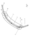
- the device for producing the splice connection consists of a curved transparent rod 1.
- This rod 1 has a triangular profile bore 2.
- an introductory shoulder 1a, 1b is arranged on the end faces of the rod 1, as is also shown in FIGS. 2 and 3, on the end faces of the rod 1, as is also shown in FIGS. 2 and 3, an introductory shoulder 1a, 1b is arranged.
Landscapes
- Physics & Mathematics (AREA)
- Engineering & Computer Science (AREA)
- Plasma & Fusion (AREA)
- General Physics & Mathematics (AREA)
- Optics & Photonics (AREA)
- Optical Couplings Of Light Guides (AREA)
- Optical Integrated Circuits (AREA)
- Manufacture, Treatment Of Glass Fibers (AREA)
- Mechanical Coupling Of Light Guides (AREA)
Abstract
Description
- Die Erfindung betrifft eine Einrichtung zur Herstellung einer mechanischen, nicht lösbaren Spleißverbindung zweier Lichtwellenleiter aus Quarzglas.
- Bei einem optischen Übertragungssystem ist es erforderlich, Lichtwellenleiter sowohl miteinander als auch mit einem Empfänger oder Sender zu verbinden. Bei der Verbindung von Lichtwellenleitern treten aber immer wieder Probleme auf, insbesondere dann, wenn hohe Ansprüche an die Verbindungsstelle gestellt werden.
- Ein Achsversatz, ein Winkelversatz, ein Frontflächenabstand oder eine Beschädigung der Lichtwellenleiter-Endflächen führen zu einer Dämpfung der Lichtleistung beim Durchlaufen der Verbindungsstelle.
- Die bekannten Spleißverbindungen erreichen die erforderliche Ausrichtung der Lichtwellenleiter mit unterschied-125-(x 2226)-TE lichem Aufwand. Sie besitzen jedoch komplizierte und auf enge Toleranzen hergestellte Teile, die zwar insbesondere in Verbindung mit größeren Lichtwellenleitern oder Lichtwellenleiter-Bündeln zufriedenstellend arbeiten, doch selbst bei Normung und Herstellung in großen Stückzahlen zu unverhältnismäßig hohen Kosten führen würden.
- Aus der DE-OS 28 40 101 ist beispielsweise eine lösbare Verbindung, insbesondere Steckverbindung, zur Kopplung von mindestens zwei Lichtwellenleitern bekannt.
- Hier werden die Lichtwellenleiter in v-förmigen Nuten zentriert und mit Hilfe eines Klemmstückes stirnseitig bündig geklemmt.
- Nachteilig sind auch die hohen Kosten, welche beim Herstellen der eng tolerierten Teile entstehen.
- Aufgabe der vorliegenden Erfindung ist daher, eine Einrichtung zu schaffen, die die erforderliche Verbindung auf eine einfache, genaue und billige Weise bei einer geringen Dämpfung der geführten Lichtleistung erreicht.
- Diese Aufgabe wird erfindungsgemäß dadurch gelöst, daß in einem gekrümmten transparenten Stab eine Dreiecksprofil-Bohrung und an den Stirnseiten des Stabes je ein Einführungsabsatz, der jeweils eine der Dreiecksprofil-Bohrung spiegelbildlich gegenüberliegende Dreiecks-Einführungsnut aufweist, angeordnet sind.
- Vorzugsweise dienen die Einführungsabsätze zur Aufnahme eines Klebstoffes zur Lagesicherung der Lichtwellenleiter.
- Die Spleißverbindung der Lichtwellenleiter wird am besten mit einem Betrachtungsmikroskop hergestellt. Hierbei wird zunächst ein Lichtwellenleiter bis zur Mitte in die Dreiecksbohrung des Stabes eingeführt und mit Klebstoff festgelegt.
- Anschließend wird der zweite Lichtwellenleiter von der anderen Seite eingeführt.
- Die Enden der beiden Lichtwellenleiter legen sich, bedingt durch die Krümmung der Dreiecksprofil-Bohrung, zwangsläufig in die selbe Ecke des Dreiecks.
- Mit Hilfe eines geeigneten Meßgerätes (z. B. Rückstreumeßplatz) wird der zweite Lichtwellenleiter justiert, bis die minimale Dämpfung erreicht ist. Mit der Festlegung des zweiten Lichtwellenleiters ist die Verbindung fertiggestellt.
- Die Erfindung wird anhand eines in der Zeichnung veranschaulichten Ausführungsbeispieles näher erläutert; darin zeigen:
- Fig. 1 den gekrümmten Stab mit zwei eingeführten Lichtwellenleitern nach der Erfindung;
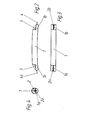
- Fig. 2 den Stab in der Vorderansicht;
- Fig. 3 den Stab in der Draufsicht; und
- Fig. 4 die Stirnseite des Stabes.
- Wie die Fig. 1 zeigt, besteht die Einrichtung zur Herstellung der Spleißverbindung aus einem gekrümmten transparenten Stab 1. Dieser Stab 1 besitzt eine Dreiecksprofil-Bohrung 2.
- An den Stirnseiten des Stabes 1 ist, wie auch die Fig. 2 und 3 zeigen, jeweils ein Einführungsabsatz la, 1b angeordnet.
- Diese Einführungsabsätze la, lb besitzen Dreiecks-Einführungsnuten 2a, 2b, die zur Dreiecksprofil-Bohrung 2 spiegelbildlich gegenüberliegen.
- Nach dem Einführen und Justieren der Enden der beiden Lichtwellenleiter 4, 4a werden diese mittels eines Klebstoffes 3, der auf die Einführungsabsätze la, lb geklebt wird, gegen ein Herausrutschen gesichert.
Claims (2)
dadurch gekennzeichnet,
daß in einem gekrümmten transparenten Stab (1) eine Dreiecksprofil-Bohrung (2) und an den Stirnseiten des Stabes (1) je ein Einführungsabsatz (la, Ib), der jeweils eine der Dreiecksprofil-Bohrung (2) spiegelbildlich gegenüberliegende Dreiecks-Einführungsnut (2a, 2b) aufweist, angeordnet sind.
daß die Einführungsabsätze (la, 1b) zur Aufnahme eines Klebstoffes (3) zur Lagesicherung der Lichtwellenleiter (4, 4a) dienen.
Applications Claiming Priority (2)
| Application Number | Priority Date | Filing Date | Title |
|---|---|---|---|
| DE3225657 | 1982-07-09 | ||
| DE19823225657 DE3225657C2 (de) | 1982-07-09 | 1982-07-09 | Einrichtung zur Herstellung einer mechanischen, nicht lösbaren Spleißverbindung zweier Lichtwellenleiter (LWL) aus Quarzglas |
Publications (2)
| Publication Number | Publication Date |
|---|---|
| EP0098548A2 true EP0098548A2 (de) | 1984-01-18 |
| EP0098548A3 EP0098548A3 (de) | 1984-07-25 |
Family
ID=6167995
Family Applications (1)
| Application Number | Title | Priority Date | Filing Date |
|---|---|---|---|
| EP83106440A Withdrawn EP0098548A3 (de) | 1982-07-09 | 1983-07-01 | Einrichtung und Verfahren zur Herstellung einer mechanischen, nicht lösbaren Spleissverbindung zweier Lichtwellenleiter aus Quarzglas |
Country Status (4)
| Country | Link |
|---|---|
| EP (1) | EP0098548A3 (de) |
| DE (1) | DE3225657C2 (de) |
| DK (1) | DK261483A (de) |
| NO (1) | NO832050L (de) |
Cited By (4)
| Publication number | Priority date | Publication date | Assignee | Title |
|---|---|---|---|---|
| EP0396313A3 (de) * | 1989-05-04 | 1991-12-04 | Corning Incorporated | Faseroptischer Stecker und Methode |
| GB2272537A (en) * | 1992-11-13 | 1994-05-18 | Seiko Giken Kk | Curved groove optical fiber splicer for ribbon-shaped optical fibre cords |
| EP0751411A1 (de) * | 1995-06-26 | 1997-01-02 | Sumitomo Electric Industries, Ltd. | Koppelröhrchen für optische Fasern, Methode zu seiner Herstellung und Methode zur Verbindung optischer Fasern |
| US6138476A (en) * | 1995-06-26 | 2000-10-31 | Sumitomo Electric Industries, Ltd. | Method of producing an optical fiber coupling member |
Families Citing this family (2)
| Publication number | Priority date | Publication date | Assignee | Title |
|---|---|---|---|---|
| DE3802240A1 (de) * | 1987-09-30 | 1989-04-20 | Krone Ag | Verbindungselement fuer lichtwellenleiter |
| DE3833369A1 (de) * | 1988-09-29 | 1990-04-05 | Siemens Ag | Verfahren zum verbinden zweier lichtwellenleiter und vorrichtung zur durchfuehrung des verfahrens |
Family Cites Families (3)
| Publication number | Priority date | Publication date | Assignee | Title |
|---|---|---|---|---|
| DE7523185U (de) * | 1975-11-06 | Siemens Ag | SpleiBelement für Einzellichtwellenleiter mit konkav gekrümmter Längsnut | |
| CA1041750A (en) * | 1975-08-26 | 1978-11-07 | Western Electric Company, Incorporated | Optical fiber splicing technique |
| DE2840101A1 (de) * | 1978-09-14 | 1980-03-27 | Siemens Ag | Loesbare verbindung, insbesondere steckverbindung, zur kopplung von mindestens zwei lichtwellenleitern |
-
1982
- 1982-07-09 DE DE19823225657 patent/DE3225657C2/de not_active Expired
-
1983
- 1983-06-07 NO NO832050A patent/NO832050L/no unknown
- 1983-06-08 DK DK261483A patent/DK261483A/da not_active Application Discontinuation
- 1983-07-01 EP EP83106440A patent/EP0098548A3/de not_active Withdrawn
Cited By (7)
| Publication number | Priority date | Publication date | Assignee | Title |
|---|---|---|---|---|
| EP0396313A3 (de) * | 1989-05-04 | 1991-12-04 | Corning Incorporated | Faseroptischer Stecker und Methode |
| GB2272537A (en) * | 1992-11-13 | 1994-05-18 | Seiko Giken Kk | Curved groove optical fiber splicer for ribbon-shaped optical fibre cords |
| GB2272537B (en) * | 1992-11-13 | 1996-10-02 | Seiko Giken Kk | Curved groove optical fiber splicer for ribbon-shaped optical fiber cords |
| EP0751411A1 (de) * | 1995-06-26 | 1997-01-02 | Sumitomo Electric Industries, Ltd. | Koppelröhrchen für optische Fasern, Methode zu seiner Herstellung und Methode zur Verbindung optischer Fasern |
| US5710850A (en) * | 1995-06-26 | 1998-01-20 | Sumitomo Electric Industries, Ltd. | Optical fiber coupling member, method of producing the same and method of connecting optical fibers |
| US5891210A (en) * | 1995-06-26 | 1999-04-06 | Sumitomo Electric Industries, Ltd. | Method of connecting optical fibers |
| US6138476A (en) * | 1995-06-26 | 2000-10-31 | Sumitomo Electric Industries, Ltd. | Method of producing an optical fiber coupling member |
Also Published As
| Publication number | Publication date |
|---|---|
| DK261483D0 (da) | 1983-06-08 |
| NO832050L (no) | 1984-01-10 |
| DE3225657A1 (de) | 1984-01-12 |
| EP0098548A3 (de) | 1984-07-25 |
| DK261483A (da) | 1984-01-10 |
| DE3225657C2 (de) | 1984-07-12 |
Similar Documents
| Publication | Publication Date | Title |
|---|---|---|
| DE68921207T2 (de) | Verfahren zur Herstellung eines faseroptischen Steckers. | |
| DE2363986C3 (de) | ||
| DE2622607C3 (de) | Selbstzentrierende Steckverbindungsanordnung für Lichtwellenleiter | |
| DE2549316A1 (de) | Verfahren und vorrichtung zum axialen ausrichten und aneinanderstossen eines sich gegenueberliegenden paares optischer fasern | |
| DE3518765A1 (de) | Verbinder fuer optische fasern und damit verbundene bauteile | |
| DE69218480T2 (de) | Lichtwellenleiterverbindung | |
| DE3225657C2 (de) | Einrichtung zur Herstellung einer mechanischen, nicht lösbaren Spleißverbindung zweier Lichtwellenleiter (LWL) aus Quarzglas | |
| EP0129048A2 (de) | Vorrichtung zum spielfreien Verschieben von Objekten in einem Koordinatensystem | |
| DE2733167C2 (de) | Armatur zum Steckverbinden zweier Lichtleitfasern | |
| EP0176820A2 (de) | Steckerteil für lösbare Steckverbindungen von Lichtwellenleitern | |
| DE2746497A1 (de) | Lichtleiteranschluss fuer optische koppelanordnungen | |
| DE3911700A1 (de) | Optisches verbindungsstueck | |
| DE3786737T2 (de) | Faseroptischer Verbinder. | |
| DE2708014C3 (de) | Stecker zur Ankopplung eines Einzellichtwellenleiters an einen anderen Einzellichtwellenleiter oder an einen Lichtsender oder Lichtempfänger | |
| DE3308679A1 (de) | Steckverbinder fuer lichtwellenleiter | |
| EP0009117A1 (de) | Lösbare Verbindung, insbesondere Steckverbindung, zur Kopplung von mindestens zwei Lichtwellenleitern | |
| DE69011311T2 (de) | Wiederverwendbarer faseroptischer mechanischer Verbinder. | |
| DE10203961C1 (de) | Koppelanordnung zum Ankoppeln eines optischen Steckers mit einem Steckerstift an ein Montageröhrchen | |
| DE3516899C2 (de) | Verfahren zum Herstellen einer Lichtleitfaserverbindung | |
| EP0286013A2 (de) | Vielfach-Steckverbinder für Lichtwellenleiter | |
| DE2654537A1 (de) | Verfahren zur justierung einer lichtleitfaser in einer steckverbindung | |
| DE4240460C2 (de) | Vorrichtung zur lösbaren Verbindung von Lichtwellenleitern | |
| DE3316727A1 (de) | Loesbare verbindungsanordnung fuer mindestens zwei lichtwellenleiter | |
| DE3327575A1 (de) | Steckverbinder fuer lichtwellenleiter | |
| CH676513A5 (en) | 2-Part optical fibre coupling - has optical fibre ends held in axial alignment by co-operating holders |
Legal Events
| Date | Code | Title | Description |
|---|---|---|---|
| PUAI | Public reference made under article 153(3) epc to a published international application that has entered the european phase |
Free format text: ORIGINAL CODE: 0009012 |
|
| AK | Designated contracting states |
Designated state(s): BE CH FR GB IT LI NL SE |
|
| PUAL | Search report despatched |
Free format text: ORIGINAL CODE: 0009013 |
|
| AK | Designated contracting states |
Designated state(s): BE CH FR GB IT LI NL SE |
|
| 17P | Request for examination filed |
Effective date: 19840809 |
|
| STAA | Information on the status of an ep patent application or granted ep patent |
Free format text: STATUS: THE APPLICATION IS DEEMED TO BE WITHDRAWN |
|
| 18D | Application deemed to be withdrawn |
Effective date: 19870203 |
|
| RIN1 | Information on inventor provided before grant (corrected) |
Inventor name: LE-HIEP, TUYEN, DR. Inventor name: ROESELER, VOLKER Inventor name: BISCHOFF, RAINER |