EP0098528A2 - Refuse receptacle - Google Patents
Refuse receptacle Download PDFInfo
- Publication number
- EP0098528A2 EP0098528A2 EP83106367A EP83106367A EP0098528A2 EP 0098528 A2 EP0098528 A2 EP 0098528A2 EP 83106367 A EP83106367 A EP 83106367A EP 83106367 A EP83106367 A EP 83106367A EP 0098528 A2 EP0098528 A2 EP 0098528A2
- Authority
- EP
- European Patent Office
- Prior art keywords
- garbage container
- guide
- container according
- gripper
- side wall
- Prior art date
- Legal status (The legal status is an assumption and is not a legal conclusion. Google has not performed a legal analysis and makes no representation as to the accuracy of the status listed.)
- Granted
Links
Images
Classifications
-
- B—PERFORMING OPERATIONS; TRANSPORTING
- B65—CONVEYING; PACKING; STORING; HANDLING THIN OR FILAMENTARY MATERIAL
- B65F—GATHERING OR REMOVAL OF DOMESTIC OR LIKE REFUSE
- B65F1/00—Refuse receptacles; Accessories therefor
- B65F1/02—Refuse receptacles; Accessories therefor without removable inserts
-
- B—PERFORMING OPERATIONS; TRANSPORTING
- B65—CONVEYING; PACKING; STORING; HANDLING THIN OR FILAMENTARY MATERIAL
- B65F—GATHERING OR REMOVAL OF DOMESTIC OR LIKE REFUSE
- B65F1/00—Refuse receptacles; Accessories therefor
- B65F1/12—Refuse receptacles; Accessories therefor with devices facilitating emptying
- B65F1/122—Features allowing the receptacle to be lifted and subsequently tipped by associated means on a vehicle
-
- B—PERFORMING OPERATIONS; TRANSPORTING
- B65—CONVEYING; PACKING; STORING; HANDLING THIN OR FILAMENTARY MATERIAL
- B65F—GATHERING OR REMOVAL OF DOMESTIC OR LIKE REFUSE
- B65F2220/00—Properties of refuse receptacles
- B65F2220/12—Properties of refuse receptacles nestable
Definitions
- the invention relates to a garbage container, in particular a plastic garbage container, with a garbage space bounded by a floor and side walls and edge profiles extending along the upper edges of the side walls, the edge profile on at least one side wall (receiving side wall) from below Has accessible cavity (receiving cavity) for the engagement of a gripper that has incisions and supporting edges extending between the incisions.
- the edge profiling on the receiving side wall is stiffened by ribs which are spaced such that they come to rest in the incisions of the gripper. Lateral alignment is also not achieved with this, since the width of the incisions in the gripper is a multiple of the rib thickness.
- the Erfincjung is based on the task of designing a waste container of the type mentioned at the outset in such a way that it is laterally aligned on the gripper without aids on the refuse vehicle.
- guide surfaces and / or guide edges for cooperation with the gripper are arranged in the area below and / or within the receiving cavity in such a way that the side edges of the incisions of the gripper in the event of poor alignment of the refuse container along the gripper slide along the guide surfaces and / or the guide edges and align the container sideways.
- Guide surfaces arranged in the area below the cavity are particularly advantageous, since the alignment process begins with such guide surfaces before the gripper has penetrated into the receiving elevation. There is a great way for the alignment. An alignment effect can also be achieved if the gripper rail approaches the waste container horizontally, or the waste container is pushed horizontally onto the gripper rail. With an arrangement of the guide surfaces according to claim 3, the alignment is achieved with a horizontal relative displacement between the gripper and waste container. In one embodiment according to claim 4, the alignment takes place with vertical movement of the gripper relative to the waste container, while in the embodiment according to claim 5, alignment takes place both with horizontal relative movement and with vertical relative movement between gripper and waste container.
- the guide surfaces are preferably arranged symmetrically to the transverse center of the receiving side wall (claim 6). It is sufficient to accomplish the lateral alignment within a single cutout of the gripper. However, several sections can also be used for this.
- the connection of the guide surfaces via convexly curved surfaces according to claim 7 has the advantage that the connecting surface already has a guiding effect. This is particularly advantageous at the lower end of guide surfaces converging in the vertical direction. End faces according to claims 8 and 9 are advantageous for the appearance of the garbage container. With the measure of claim 9 you avoid protruding parts over the upper edge of the container and still use the largest possible path for centering.
- Base areas according to claim 10 have the advantage that after the lateral alignment has taken place, there is a stable lateral contact within the incisions.
- the structural design with which the guide surfaces and / or the guide edges are formed also depends heavily on the manufacturing process by which the waste container is manufactured.
- a waste container made of plastic which is produced by injection molding, it is advantageous that the guide surfaces are formed by guide walls integral with the waste container. If one provides a downward open cavity according to claim 15, the guide walls can be produced with a simple tool. However, one must then be satisfied with guide surfaces which only converge in the horizontal direction, since undercuts which are naturally present have to be avoided with a simple tool if there is also convergence in the vertical direction. A certain guidance in the vertical direction can also be achieved if the lower edges of the guide walls run obliquely.
- Guide walls of any shape that is to say walls which converge in the vertical direction, can be produced relatively easily in an injection molding process in a design according to claim 17.
- a niche must then be accepted in the garbage room, which is generally not desirable there.
- Such a niche can be avoided if, according to claim 18, a separately produced filler is inserted into the mold and overmoulded, or also in that, according to claim 19, a separately produced guide body is used which is fused to the waste container. A particularly good connection is obtained with the means of claim 20.
- Another possibility is the use of a separately produced guide body which is placed on the waste container (claims 21 and 22).
- the invention is possible in principle with straight and curved receiving cavities.
- Straight receiving cavities according to claim 23 are customary.
- the invention is explained using the example of garbage containers which are designed as plastic injection molded parts.
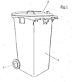
- the garbage container consists essentially of a box-shaped lower part 1 of approximately square horizontal cross-section, which contains the garbage room, a closing the garbage room hinged cover 2 and a trolley 3, which consists of two rollers.
- an edge profile 4 along the upper edge of the lower part 1 extends an edge profile 4, with which a suitable edge for the placement of the refuse container when it is automatically emptied is formed; at the same time, the edge profiling stiffens the opening of the box 1.
- the container When the garbage container is automatically emptied with a garbage collecting vehicle, the container is received at the upper edge of its side wall 5, which is therefore referred to as the receiving side wall.
- a gripper which is usually designed as a straight rail, engages under the edge profile 4, which extends along the upper edge of the receiving side wall.
- the gripper has horizontal supporting edges and vertical incisions. It is important that the garbage container is aligned relatively precisely on the gripper so that the upper opening of the container comes to rest securely on the corresponding filling opening of the garbage collecting vehicle when it is tilted.
- a body, generally designated 6, is arranged on the receiving side wall 5 and is formed in one piece with the refuse container.
- the body 6 has base walls 7, 8 which are approximately at right angles to the receiving side wall 5.
- the base walls 7, 8 merge into guide walls 9, 10, which converge with increasing distance from the receiving side wall 5.
- the guide walls 9, 10 form guide surfaces 9a, 10a, which are arranged symmetrically with respect to the transverse center marked by the dash-dotted line 11 of a receiving cavity designated overall by 12.
- the guide walls 9, 10 are connected to one another via an end wall 13 which lies in the same plane as an end wall 14 of the receiving cavity 12.
- the walls of the projection 6 have lower end edges which run obliquely upwards.
- the end edges project into a straight line 15 in FIG. 5.
- the walls of the receiving cavity 12 are heavily ribbed in order to be sufficiently stable for the support by the supporting edges of the gripper.
- the ribbing of the upper wall 16 consists of a system of longitudinal ribs 17, 18 and transverse ribs 19 crossing at right angles.
- the longitudinal rib 17 is pulled down at its ends (regions 17a and 17b). These rib areas form guide edges 20 and 21, which further contribute to the lateral alignment of the container relative to the gripper.
- the guide surfaces 9a and 10a converge only in the horizontal direction.
- the projection 6, which forms the guide surfaces, has a hollow 22 which is open at the bottom. This design enables the projection 6 to be produced in one piece with the lower container part 1 with a simple tool, since there are no undercuts.
- the alignment effect of the guide surfaces 9a and 10a occurs when there is a horizontal movement between the waste container and the gripper. In the area of the guide edges 20 and 21 (of course, corresponding guide edges are present to the right of the transverse center 11), a vertical relative movement between the gripper and the container has an aligning effect.
- the gripper G indicated by dash-dotted lines engages with the corners of its cutouts A in the inner corners which exist between the horizontal part of the longitudinal rib 17 and the guide edges 20, 21. After the gripper G has penetrated into the receiving cavity 12, the horizontal movements of the gripper are relative to the waste container anyway only very limited or not possible at all.
- a nose-shaped body 23 is formed on the receiving side wall 5 in the area below the receiving cavity 12.
- the body 23 has guide surfaces 24 and 25 which are both in. converge downwards in the vertical direction as well as in the horizontal direction with increasing distance from the receiving side wall 5.
- the guide surfaces 24, 25 are connected via an end wall 26, which again lies in the plane of the end wall 27 of the receiving cavity 12. At the lower end, the guide surfaces are connected to one another by a convex surface 28. At their upper ends, the guide surfaces 24, 25 merge into further guide surfaces 29, 30, which only converge in the horizontal direction.
- the body 23 is formed in one piece with the waste container, the wall 5 bulging outwards at the location of the body 23.
- the production is extremely simple. However, an inner wall that runs smoothly right up to the top must be dispensed with.
- the nose-like projection 23 acts due to the double inclination of the guide surfaces 24, 25, so to speak, both when the gripper is moved horizontally towards the wall 5 and when the gripper moves vertically relative to the container.
- guide edges 20 and 21 are provided in addition to the guide surfaces 24, 25.
- the disadvantage just mentioned that the inner wall of the container is not continuously smooth is avoided, although also here there is a guide projection 31 which has guide surfaces 32 and 33 which converge both horizontally and vertically.
- the outer shape of the body 31 is of the same design as that of the nose-shaped projection 23 according to FIGS. 9 and 10; only the proportions are slightly different.
- the guide surfaces 32, 33 and the transition surfaces between these guide surfaces are formed here by an attached body 34.
- the body 34 is preferably also a plastic injection molded part.
- the attachment takes place in that the body is pushed onto ribs 35, 36 which are formed on the receiving side wall 5 of the container.
- the ribs 35, 36 have lateral projections 37 of a T-shaped cross section in order to make the contact surface with the body 34 even larger and thus to make the connection even more secure.
- the body 34 also engages in the receiving cavity 12 and also forms guide surfaces there. For additional protection against sliding of the body 34, an adhesive bond or a mechanical locking can be produced between the body and the ribs 35-, 36.
- the outer shape of the guide lug 38 is the same as in the embodiment according to FIGS. 11 to 14.
- the guide surfaces 39, 40 are formed here by the surface of a body 41, which is manufactured separately before the garbage container is formed, but when the garbage container is formed Garbage container was fused with this.
- the body 41 contains a plurality of parallel grooves 42 to 46. When the garbage container is formed, the plastic flows into the grooves 42 to 46, the groove walls being melted somewhat, so that welding with the material of the garbage container takes place. The filling of the grooves forms a kind of ribs 47 to 51.
- the rib 49 can be seen in view in FIG. 18.
Landscapes
- Engineering & Computer Science (AREA)
- Mechanical Engineering (AREA)
- Refuse Receptacles (AREA)
Abstract
An der Behälterseite (5), an der der Müllbehälter mit einem Greifer erfaßt wird, ist ein Vorsprung (23) angeordnet, an dem sich Führungsflächen (24, 25) befinden. Wenn der Müllbehälter vom Greifer eines Müll-Sammelfahrzeuges erfaßt werden soll, gleitet der Greifer auf die Führungsflächen (24, 25) auf und bewirkt eine seitliche Ausrichtung des Müllbehälters relativ zum Greifer auf die Führungsflächen (24, 25) auf und bewirkt eine seitliche Ausrichtung des Müllbehälters relativ zum Greifer. Innerhalb der Höhlung (12) befinden sich Führungskanten (20, 21), an denen eine weitere seitliche Ausrichtung dadurch stattfindet, daß die Führungskanten in Einschnitte des Greifers hineingleiten.On the container side (5), on which the waste container is gripped with a gripper, there is a projection (23) on which there are guide surfaces (24, 25). If the garbage container is to be gripped by the gripper of a garbage collection vehicle, the gripper slides onto the guide surfaces (24, 25) and causes the garbage container to be laterally aligned relative to the gripper on the guide surfaces (24, 25) and causes a lateral orientation of the Garbage container relative to the gripper. Inside the cavity (12) there are guide edges (20, 21) on which a further lateral alignment takes place in that the guide edges slide into incisions in the gripper.
Durch die Führungsmittel (24, 25, 20, 21) wird eine seitliche Ausrichtung erreicht, ohne daß hierfür an einem Müll-Sammelfahrzeug besondere Vorkehrungen getroffen werden müssen.
Description
Die Erfindung bezieht sich auf einen Müllbehälter, insbesondere auf einen Müllbehälter aus Kunststoff, mit einem von einem Boden und Seitenwänden begrenzten Müllraum und längs den oberen Rändern der Seitenwände sich erstreckenden Randprofilierungen, wobei die Randprofilierung an mindestens einer Seitenwand (Aufnahme-Seitenwand) eine von unten zugängliche Höhlung (Aufnahmehöhlung) für den Eingriff eines Greifers aufweist, der Einschnitte und zwischen den Einschnitten sich erstreckende Tragkanten hat.The invention relates to a garbage container, in particular a plastic garbage container, with a garbage space bounded by a floor and side walls and edge profiles extending along the upper edges of the side walls, the edge profile on at least one side wall (receiving side wall) from below Has accessible cavity (receiving cavity) for the engagement of a gripper that has incisions and supporting edges extending between the incisions.
Beim Aufnehmen von Müllbehältern kommt es darauf an, daß diese exakt auf den Greifer ausgerichtet werden. Nur dadurch ist gewährleistet, daß die obere öffnung des Müllbehälters beim Entleeren exakt auf die Füllöffnung des einsammelnden Müllfahrzeuges ausgerichtet ist. Die Einschnitte im Greifer sind relativ breit, um zu gewährleisten, daß auch dann, wenn der Müllbehälter nach dem Heranfahren an die Greiferschiene seitlich nur grob ausgerichtet ist, die Einschnitte sicher die Enden der Randprofilierung umfassen. Die genaue seitliche Ausrichtung muß dann mit Hilfe von Einrichtungen am Müllfahrzeug erfolgen.When picking up garbage containers, it is important that they are precisely aligned with the gripper. This is the only way to ensure that the upper opening of the waste container is exactly aligned with the filling opening of the collecting waste vehicle when it is emptied. The incisions in the gripper are relatively wide to ensure that even if the waste container is only roughly aligned laterally after approaching the gripper rail, the incisions reliably encompass the ends of the edge profiling. The exact lateral alignment must then be done with the help of facilities on the garbage truck.
Bei einem bekannten Müllbehälter der eingangs genannten Art (DE-PS 21 56 013) ist die Randprofilierung an der Aufnahme-Seitenwand durch Rippen abgesteift, die solche Abstände haben, daß sie in die Einschnitte des Greifers zu liegen kommen. Auch damit wird eine seitliche Ausrichtung nicht erreicht, da die Breite der Einschnitte im Greifer ein Vielfaches der Rippendicke ist.In a known waste container of the type mentioned (DE-PS 21 56 013), the edge profiling on the receiving side wall is stiffened by ribs which are spaced such that they come to rest in the incisions of the gripper. Lateral alignment is also not achieved with this, since the width of the incisions in the gripper is a multiple of the rib thickness.
Der Erfincjung liegt die Aufgabe zugrunde, einen Müllbehälter der eingangs genannten Art so auszubilden, daß er ohne Hilfsmittel am Müllfahrzeug am Greifer seitlich ausgerichtet wird.The Erfincjung is based on the task of designing a waste container of the type mentioned at the outset in such a way that it is laterally aligned on the gripper without aids on the refuse vehicle.
Diese Aufgabe wird nach der Erfindung dadurch gelöst, daß im Bereich unterhalb und/oder innerhalb der Aufnahmehöhlung Führungsflächen und/oder Führungskanten für das Zusammenwirken mit dem Greifer so angeordnet sind, daß die Seitenkanten der Einschnitte des Greifers bei mangelhafter Ausrichtung des Müllbehälters längs des Greifers an den Führungsflächen und/oder den Führungskanten entlanggleiten und dabei den Behälter seitlich ausrichten.This object is achieved according to the invention in that guide surfaces and / or guide edges for cooperation with the gripper are arranged in the area below and / or within the receiving cavity in such a way that the side edges of the incisions of the gripper in the event of poor alignment of the refuse container along the gripper slide along the guide surfaces and / or the guide edges and align the container sideways.
Bei einem so ausgebildeten Müllbehälter brauchen weder an dem Greifer noch an sonstigen Teilen des Müllfahrzeuges Einrichtungen vorgesehen zu werden, mit denen die Müllbehälter exakt ausgerichtet werden. Bei Annäherung des Greifers an den Müllbehälter gleiten die Führungsflächen in mindestens einen Ausschnitt, wodurch sich die gewünschte exakte Ausrichtung von selber ergibt.In the case of a refuse container designed in this way, devices with which the refuse containers are exactly aligned need not be provided on the gripper or on other parts of the refuse vehicle. When the gripper approaches the waste container, the guide surfaces slide into at least one cutout, which results in the desired exact alignment of itself.
Es sind verschiedene Ausführungsformen der Erfindung möglich, die in den Unteransprüchen angegeben sind. Zu den einzelnen Unteransprüchen wird folgendes bemerkt.Various embodiments of the invention are possible, which are specified in the subclaims. The following is noted regarding the individual subclaims.
Besonders vorteilhaft sind im Bereich unterhalb der Höhlung angeordnete Führungsflächen gemäß Anspruch 2, da mit solchen Führungsflächen der Ausrichtvorgang beginnt, bevor der Greifer in die Aufnahmehöhung eingedrungen ist. Für die Ausrichtung steht damit ein großer Weg zur Verfügung. Auch kann eine Ausrichtwirkung bereits erzielt werden, wenn sich die Greiferschiene horizontal an den Müllbehälter annähert, bzw. der Müllbehälter horizontal an die Greiferschiene herangeschoben wird. Mit einer Anordnung der Führungsflächen gemäß Anspruch 3 wird die Ausrichtung bei horizontaler Relativverschiebung zwischen Greifer und Müllbehälter erreicht. Bei einer Ausführungsform nach Anspruch 4 erfolgt die Ausrichtung bei vertikaler Bewegung des Greifers relativ zum Müllbehälter, während bei der Ausführungsform nach Anspruch 5 sowohl bei horizontaler Relativbewegung als auch bei vertikaler Relativbewegung zwischen Greifer und Müllbehälter eine Ausrichtung stattfindet.Guide surfaces arranged in the area below the cavity are particularly advantageous, since the alignment process begins with such guide surfaces before the gripper has penetrated into the receiving elevation. There is a great way for the alignment. An alignment effect can also be achieved if the gripper rail approaches the waste container horizontally, or the waste container is pushed horizontally onto the gripper rail. With an arrangement of the guide surfaces according to
Die Führungsflächen sind vorzugsweise symmetrisch zur Quermitte der Aufnahme-Seitenwand angeordnet (Anspruch 6). Hierbei genügt es, die seitliche Ausrichtung innerhalb eines einzigen Ausschnittes des Greifers zu bewerkstelligen. Es können jedoch auch mehrere Ausschnitte hierfür herangezogen werden. Die Verbindung der Führungsflächen über konvex gewölbte Flächen gemäß Anspruch 7 hat den Vorteil, daß auch die Verbindungsfläche bereits eine Führungswirkung hat. Besonders vorteilhaft ist dies am unteren Ende von in vertikaler Richtung konvergierenden Führungsflächen. Endflächen gemäß den Ansprüchen 8 und 9 sind für das Aussehen des Müllbehälters von Vorteil. Mit der Maßnahme des Anspruches 9 vermeidet man über den oberen Rand des Behälters vorragende Teile und nutzt dennoch einen möglichst großen Weg für die Zentrierung aus. Basisflächen gemäß Anspruch 10 haben den Vorteil, daß nach erfolgter seitlicher Ausrichtung eine stabile seitliche Anlage innerhalb der Einschnitte gegeben ist.The guide surfaces are preferably arranged symmetrically to the transverse center of the receiving side wall (claim 6). It is sufficient to accomplish the lateral alignment within a single cutout of the gripper. However, several sections can also be used for this. The connection of the guide surfaces via convexly curved surfaces according to claim 7 has the advantage that the connecting surface already has a guiding effect. This is particularly advantageous at the lower end of guide surfaces converging in the vertical direction. End faces according to
Besonders vorteilhaft ist die Kombination von Führungsflächen und Führungskanten gemäß den Ansprüchen 11 bis 13. Man erreicht dadurch, daß der Ausrichtvorgang auch noch fortgesetzt wird, wenn der Greifer bereits in die Aufnahmehöhlung eingedrungen ist.The combination of guide surfaces and guide edges according to claims 11 to 13 is particularly advantageous. In this way, the alignment process is continued even when the gripper has already penetrated the receiving cavity.
Die konstruktive Gestaltung, mit der die Führungsflächen und/oder die Führungskanten gebildet werden, hängt auch stark von dem Fertigungsverfahren ab, nach dem der Müllbehälter hergestellt wird. Bei einem Müllbehälter aus Kunststoff, der im Spritzgußverfahren hergestellt wird, ist es vorteilhaft, daß die Führungsflächen gemäß Anspruch 14 durch mit dem Müllbehälter einstückige Führungswände gebildet werden. Wenn man eine nach unten offene Höhlung gemäß Anspruch 15 vorsieht, lassen sich die Führungswände mit einem einfachen Werkzeug herstellen. Allerdings muß man sich dann mit Führungsflächen begnügen, die nur in horizontaler Richtung konvergieren, da ja bei einem einfachen Werkzeug Hinterschneidungen vermieden werden müssen, die naturgemäß vorhanden sind, wenn eine Konvergenz auch in vertikaler Richtung vorhanden ist. Eine gewisse Führung in vertikaler Richtung läßt sich aber auch dann erreichen, wenn die unteren Kanten der Führungswände gemäß Anspruch 16 schräg verlaufen.The structural design with which the guide surfaces and / or the guide edges are formed also depends heavily on the manufacturing process by which the waste container is manufactured. In a waste container made of plastic, which is produced by injection molding, it is advantageous that the guide surfaces are formed by guide walls integral with the waste container. If one provides a downward open cavity according to
Beliebig geformte Führungswände, also auch in vertiakaler Richtung konvergierende Wände,lassen sich im Spritzgußverfahren relativ einfach bei einer Gestaltung gemäß Anspruch 17 herstellen. Allerdings muß dann im Müllraum eine Nische in Kauf genommen werden, die dort im allgemeinen nicht erwünscht ist. Man kann eine solche Nische umgehen, wenn gemäß Anspruch 18 ein separat hergestellter Füllkörper in die Form eingelegt und umspritzt wird oder auch dadurch, daß gemäß Anspruch 19 ein separat hergestellter Führungskörper verwendet wird, der mit dem Müllbehälter verschmolzen ist. Eine besonders gute Verbindung erhält man mit den Mitteln des Anspruches 20. Eine weitere Möglichkeit besteht in der Verwendung eines separat hergestellten Führungskörpers, der auf den Müllbehälter aufgesetzt ist (Ansprüche 21 und 22).Guide walls of any shape, that is to say walls which converge in the vertical direction, can be produced relatively easily in an injection molding process in a design according to
Die Erfindung ist im Prinzip bei geraden und gekrümmten Aufnahmehöhlungen möglich. Üblich sind gerade Aufnahmehöhlungen gemäß Anspruch 23.The invention is possible in principle with straight and curved receiving cavities. Straight receiving cavities according to
In der Zeichnung sind Ausführungsbeispiele der Erfindung dargestellt. Es zeigen:
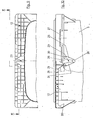
- Fig. 1 einen fahrbaren Müllbehälter aus Kunststoff in perspektivischer Darstellung,
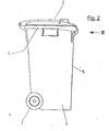
- Fig. 2 eine Seitenansicht des Müllbehälters nach Fig. 1,
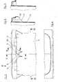
- Fig. 3 den oberen Bereich des Müllbehälters nach den Fig. 1 und 2, gesehen in Richtung des Pfeiles III, wobei jedoch in Fig. 3 der Deckel weggelassen ist,
- Fig. 4 eine teilweise Draufsicht in Richtung des Pfeiles IV in Fig. 3,
- Fig. 5 einen Schnitt nach Linie V-V in Fig. 3,
- Fig. 6 einen Schnitt nach Linie VI-VI in Fig. 3,
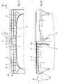
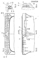
- Fig. 7 eine teilweise Unteransicht entsprechend den Pfeilen VII-VII in Fig. 3,
- Fig. 8 einen Schnitt nach Linie VIII-VIII in Fig. 7,
- Fig. 9 eine der Fig. 7 entsprechende Unteransicht bei einer zweiten Ausführungsform der Erfindung,
- Fig.10 einen Schnitt nach Linie X-X in Fig. 9,
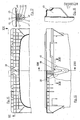
- Fig.11 eine den Fig. 7 und 9 entsprechende Unteransicht bei einer dritten Ausführungsform der Erfindung,
- Fig.12 einen Schnitt nach Linie XII-XII in Fig. 11,
- Fig.13 einen Schnitt nach Linie XIII-XIII in Fig. 12,
- Fig.14 einen Schnitt nach Linie XIV-XIV in Fig.12,
- Fig.15 eine Unteransicht entsprechend den Fig. 7, 9, 13 bei einer vierten Ausführungsform der Erfindung,
- Fig.16 einen Schnitt nach Linie XVI-XVI in Fig. 15,
- Fig.17 einen Schnitt nach Linie XVII-XVII in Fig. 16 und
- Fig.18 einen Schnitt nach Linie XVIII-XVIII in Fig. 16.
- 1 is a mobile waste container made of plastic in a perspective view,
- 2 is a side view of the garbage container of FIG. 1,
- 3 shows the upper region of the refuse container according to FIGS. 1 and 2, viewed in the direction of arrow III, but the lid is omitted in FIG. 3,
- 4 is a partial plan view in the direction of arrow IV in FIG. 3,
- 5 shows a section along line VV in FIG. 3,
- 6 shows a section along line VI-VI in FIG. 3,
- 7 is a partial bottom view according to the arrows VII-VII in Fig. 3,
- 8 shows a section along line VIII-VIII in FIG. 7,
- 9 is a bottom view corresponding to FIG. 7 in a second embodiment of the invention,
- 10 shows a section along line XX in FIG. 9,
- 11 is a bottom view corresponding to FIGS. 7 and 9 in a third embodiment of the invention,
- 12 shows a section along line XII-XII in FIG. 11,
- 13 shows a section along line XIII-XIII in FIG. 12,
- 14 shows a section along line XIV-XIV in FIG. 12,
- 15 is a bottom view corresponding to FIGS. 7, 9, 13 in a fourth embodiment of the invention,
- 16 shows a section along line XVI-XVI in FIG. 15,
- Fig.17 shows a section along line XVII-XVII in Fig. 16 and
- 18 shows a section along line XVIII-XVIII in FIG. 16.
Die Erfindung wird am Beispiel von Müllbehältern erläutert, die als Kunststoff-Spritzteile ausgebildet sind. Der Müllbehälter besteht im wesentlichen aus einem kastenförmigen Unterteil 1 von etwa quadratischem horizontalem Querschnitt, der den Müllraum enthält, einen den Müllraum abschließenden zurückklappbaren Deckel 2 und einem Fahrwerk 3, das aus zwei Laufrollen besteht. Längs dem oberen Rand des Unterteiles 1 erstreckt sich eine Randprofilierung 4, mit der ein für das Aufsetzen des Müllbehälters bei seiner automatischen Entleerung geeigneter Rand gebildet wird; zugleich bewirkt die Randprofilierung eine Versteifung der öffnung des Kastens 1.The invention is explained using the example of garbage containers which are designed as plastic injection molded parts. The garbage container consists essentially of a box-shaped lower part 1 of approximately square horizontal cross-section, which contains the garbage room, a closing the garbage room hinged
Bei der automatischen Entleerung des Müllbehälters mit einem Müll-Sammelfahrzeug wird der Behälter am oberen Rand seiner Seitenwand 5 aufgenommen, die deshalb als Aufnahme-Seitenwand bezeichnet wird. Hierbei greift ein Greifer, der meist als gerade Schiene ausgebildet ist, unter die Randprofilierung 4, die sich längs dem oberen Rand der Aufnahme-Seitenwand erstreckt. Der Greifer hat horizontale Tragkanten und vertikale Einschnitte. Es ist wichtig, daß der Müllbehälter verhältnismäßig genau am Greifer ausgerichtet wird, damit die obere öffnung des Behälters beim Kippen sicher auf die korrespondierende Füllöffnung des Müll-Sammelfahrzeuges zu liegen kommt.When the garbage container is automatically emptied with a garbage collecting vehicle, the container is received at the upper edge of its
Bei der Ausführungsform der Erfindung nach den Fig. 1 bis 8 ist an der Aufnahme-Seitenwand 5 ein insgesamt mit 6 bezeichneter Körper angeordnet, der einstückig mit dem Müllbehälter ausgebildet ist. Der Körper 6 hat Basiswände 7, 8, die annähernd rechtwinklig zur Aufnahme-Seitenwand 5 stehen. Die Basiswände 7, 8 gehen in Führungswände 9, 10 über, die mit zunehmender Entfernung von der Aufnahme-Seitenwand 5 konvergieren. Die Führungswände 9, 10 bilden Führungsflächen 9a, 10a, die symmetrisch zu der durch die strichpunktierte Linie 11 markierten Quermitte einer insgesamt mit 12 bezeichneten Aufnahmehöhlung angeordnet sind. Die Führungswände 9, 10 sind über eine Endwand 13 miteinander verbunden, die in der gleichen Ebene liegt wie eine Endwand 14 der Aufnahmehöhlung 12.In the embodiment of the invention according to FIGS. 1 to 8, a body, generally designated 6, is arranged on the receiving
Wie man insbesondere aus Fig. 5 ersehen kann, haben die Wände des Vorsprunges 6 untere Endkanten, die schräg nach oben verlaufen. Die Endkanten projizieren sich in Fig. 5 in eine gerade Linie 15.As can be seen in particular from Fig. 5, the walls of the projection 6 have lower end edges which run obliquely upwards. The end edges project into a
Wie die Unteransicht nach Fig. 7 und der Schnitt nach Fig. 8 zeigt, sind die Wände der Aufnahmehöhlung 12 stark verrippt, um für die Unterstützung durch die Tragkanten des Greifers genügend stabil zu sein. Die Verrippung der oberen Wand 16 besteht aus einem System von sich rechtwinklig kreuzenden Längsrippen 17, 18 und Querrippen 19. Wie man aus Fig. 8 ersehen kann, ist die Längsrippe 17 an ihren Enden nach unten gezogen (Bereiche 17a und 17b). Diese Rippenbereiche bilden Führungskanten 20 und 21, die weiterhin zur seitlichen Ausrichtung des Behälters relativ zum Greifer beitragen.As the bottom view according to FIG. 7 and the section according to FIG. 8 show, the walls of the receiving
Die Führungsflächen 9a und 10a konvergieren nur in horizontaler Richtung. Der Vorsprung 6, der die Führungsflächen bildet, hat eine nach unten offene Höhlung 22. Diese Formgestaltung ermöglicht die Herstellung des Vorsprunges 6 aus einem Stück mit dem Behälterunterteil 1 mit einem einfachen Werkzeug, da Hinterschneidungen nicht vorhanden sind. Die Ausrichtwirkung der Führungsflächen 9a und 10a entsteht, wenn zwischen Müllbehälter und Greifer eine Horizontalbewegung vorhanden ist. Im Bereich der Führungskanten 20 und 21 (rechts von der Quermitte 11 sind natürlich entsprechende Führungskanten vorhanden) wirken bei einer vertikalen Relativbewegung zwischen Greifer und Behälter ausrichtend. Nach vollständiger Ausrichtung greift der strichpunktiert angedeutete Greifer G mit Ecken seiner Ausschnitte A in die Innenecken ein, die zwischen dem horizontalen Teil der Längsrippe 17 und den Führungskanten 20, 21 bestehen. Nach dem Eindringen des Greifers G in die Aufnahmehöhlung 12 sind Horizontalbewegungen des Greifers relativ zum Müllbehälter ohnehin nur noch sehr begrenzt oder auch überhaupt nicht möglich.The guide surfaces 9a and 10a converge only in the horizontal direction. The projection 6, which forms the guide surfaces, has a hollow 22 which is open at the bottom. This design enables the projection 6 to be produced in one piece with the lower container part 1 with a simple tool, since there are no undercuts. The alignment effect of the guide surfaces 9a and 10a occurs when there is a horizontal movement between the waste container and the gripper. In the area of the guide edges 20 and 21 (of course, corresponding guide edges are present to the right of the transverse center 11), a vertical relative movement between the gripper and the container has an aligning effect. After complete alignment, the gripper G indicated by dash-dotted lines engages with the corners of its cutouts A in the inner corners which exist between the horizontal part of the
Bei der Ausführungsform nach den Fig. 9 und 10 ist im Bereich unterhalb der Aufnahmehöhlung 12 an die Aufnahme-Seitenwand 5 ein nasenförmiger Körper 23 angeformt. Der Körper 23 hat Führungsflächen 24 und 25, die sowohl in . vertikaler Richtung nach unten konvergieren als auch in horizontaler Richtung mit zunehmender Entfernung von der Aufnahme-Seitenwand 5. Die Führungsflächen 24, 25 sind über eine Endwand 26 verbunden, die wieder in der Ebene der Endwand 27 der Aufnahmehöhlung 12 liegt. Am unteren Ende sind die Führungsflächen durch eine konvexe Fläche 28 miteinander verbunden. Die Führungsflächen 24, 25 gehen an ihren oberen Enden in weitere Führungsflächen 29, 30 über, die nur noch in horizontaler Richtung konvergieren.In the embodiment according to FIGS. 9 and 10, a nose-shaped
Der Körper 23 ist einstückig mit dem Müllbehälter ausgebildet, wobei die Wand 5 an der Stelle des Körpers 23 nach außen ausgewölbt ist. Die Herstellung ist damit außerordentlich einfach. Allerdings muß auf eine bis ganz oben hin glatt durchlaufende Innenwand verzichtet werden.The
Der nasenartige Vorsprung 23 wirkt aufgrund der sozusagen zweifachen Schrägstellung der Führungsflächen 24, 25 sowohl ausrichtend, wenn der Greifer horizontal auf die Wand 5 hin bewegt wird, als auch bei vertikaler Bewegung des Greifers relativ zu Behälter. Auch bei der Ausführungsform nach den Fig. 9 und 10 sind zusätzlich zu den Führungsflächen 24, 25 Führungskanten 20 und 21 vorgesehen.The nose-
Bei der Ausführungsform nach den Fig. 11 bis 14 wird der eben erwähnte Nachteil, daß die Innenwand des Behälters nicht durchgehend glatt ausgebildet ist, vermieden, obwohl auch hier ein Führungsvorsprung 31 vorhanden ist, der Führungsflächen 32 und 33 hat, die sowohl horizontal als auch vertikal konvergieren. Im Prinzip ist die Außenform des Körpers 31 gleich ausgebildet wie diejenige des nasenförmigen Vorsprunges 23 nach den Fig. 9 und 10; lediglich die Proportionen sind etwas anders.In the embodiment according to FIGS. 11 to 14, the disadvantage just mentioned that the inner wall of the container is not continuously smooth is avoided, although also here there is a
Die Führungsflächen 32, 33 und die Übergangsflächen zwischen diesen Führungsflächen werden hier durch einen aufgesetzten Körper 34 gebildet. Vorzugsweise ist auch der Körper 34 ein Kunststoff-Spritzteil. Die Befestigung erfolgt dadurch, daß der Körper auf Rippen 35, 36 aufgeschoben wird, die an die Aufnahme-Seitenwand 5 des Behälters angeformt sind. Die Rippen 35, 36 haben seitliche Vorsprünge 37 von T-förmigem Querschnitt, um die Berührungsfläche mit dem Körper 34 noch größer und damit die Verbindung noch sicherer zu gestalten. Der Körper 34 greift auch in die Aufnahmehöhlung 12 ein und bildet auch dort Führungsflächen. Zur zusätzlichen Sicherung gegen Abgleiten des Körpers 34 kann zwischen dem Körper und den Rippen 35-, 36 eine Verklebung oder auch eine mechanische Verrastung hergestellt werden.The guide surfaces 32, 33 and the transition surfaces between these guide surfaces are formed here by an attached
In den Fig. 15 bis 18 ist eine weitere Möglichkeit dargestellt, mit der eine glatte Innenwand des Behälters möglich ist, auch wenn die Führungsflächen nach unten konvergieren. Die äußere Gestalt der Führungsnase 38 ist gleich wie bei der Ausführungsform nach den Fig. 11 bis 14. Die Führungsflächen 39, 40 werden hier durch die Oberfläche eines Körpers 41 gebildet, der zwar vor der Formung des Müllbehälters separat hergestellt, jedoch bei der Formung des Müllbehälters mit diesem verschmolzen wurde. Der Körper 41 enthält mehrere parallele Nuten 42 bis 46. Wenn der Müllbehälter geformt wird, fließt der Kunststoff in die Nuten 42 bis 46, wobei die Nutwände etwas aufgeschmolzen werden, so daß eine Verschweißung mit dem Material des Müllbehälters stattfindet. Die Ausfüllung der Nuten bildet eine Art Rippen 47 bis 51. Die Rippe 49 ist in Fig. 18 in Ansicht zu sehen.15 to 18 show a further possibility with which a smooth inner wall of the container is possible, even if the guide surfaces converge downwards. The outer shape of the
Claims (23)
Applications Claiming Priority (2)
| Application Number | Priority Date | Filing Date | Title |
|---|---|---|---|
| DE3224950 | 1982-07-03 | ||
| DE19823224950 DE3224950A1 (en) | 1982-07-03 | 1982-07-03 | WASTE CONTAINER |
Publications (4)
| Publication Number | Publication Date |
|---|---|
| EP0098528A2 true EP0098528A2 (en) | 1984-01-18 |
| EP0098528A3 EP0098528A3 (en) | 1985-05-08 |
| EP0098528B1 EP0098528B1 (en) | 1986-10-15 |
| EP0098528B2 EP0098528B2 (en) | 1991-10-02 |
Family
ID=6167566
Family Applications (1)
| Application Number | Title | Priority Date | Filing Date |
|---|---|---|---|
| EP83106367A Expired - Lifetime EP0098528B2 (en) | 1982-07-03 | 1983-06-30 | Refuse receptacle |
Country Status (2)
| Country | Link |
|---|---|
| EP (1) | EP0098528B2 (en) |
| DE (2) | DE3224950A1 (en) |
Cited By (3)
| Publication number | Priority date | Publication date | Assignee | Title |
|---|---|---|---|---|
| EP0178491A1 (en) * | 1984-10-05 | 1986-04-23 | Willem Jan Achterberg | Refuse receptacle |
| EP0288066A3 (en) * | 1987-04-22 | 1990-02-07 | Edelhoff M.S.T.S. Gmbh | Refuse receptacle |
| EP0448002A1 (en) * | 1990-03-21 | 1991-09-25 | Fritz Schäfer Gesellschaft mit beschränkter Haftung | Garbage collecting device |
Families Citing this family (4)
| Publication number | Priority date | Publication date | Assignee | Title |
|---|---|---|---|---|
| DE3614328C2 (en) * | 1986-04-28 | 1995-08-03 | Otto Lift Systeme Gmbh | Filling on a garbage truck and garbage container for this filling |
| DE10344516A1 (en) * | 2003-09-24 | 2005-04-28 | Sulo Umwelttechnik Gmbh & Co Kg | Refuse container and receiving device with increased recording tolerance |
| ES2361177T3 (en) | 2005-03-14 | 2011-06-14 | Europlast Kunststoffbehälterindustrie Gmbh | DUMPSTER. |
| AT7681U3 (en) * | 2005-03-14 | 2006-08-15 | Europlast Kunststoffbehaelteri | WASTE CONTAINERS |
Family Cites Families (4)
| Publication number | Priority date | Publication date | Assignee | Title |
|---|---|---|---|---|
| BE790761A (en) * | 1971-11-11 | 1973-02-15 | Streuber Sulo Eisenwerk F | LARGE CAPACITY GARBAGE CONTAINER, MOBILE, SYNTHETIC MATERIAL |
| DE7341710U (en) * | 1973-03-09 | 1974-02-28 | Fusion Rubbermaid Bv | Waste collection container and tipping device therefor |
| DE2648209C2 (en) * | 1976-10-25 | 1981-04-16 | Schneider Städtereinigung GmbH & Co KG, 6346 Oberscheld | Reinforcement for the straight hanging rail of a rectangular plastic garbage can |
| DE7710913U1 (en) * | 1977-04-06 | 1977-07-21 | Sulo Eisenwerk Streuber & Lohmann, 4900 Herford | Plastic rubbish bins |
-
1982
- 1982-07-03 DE DE19823224950 patent/DE3224950A1/en active Granted
-
1983
- 1983-06-30 DE DE8383106367T patent/DE3366895D1/en not_active Expired
- 1983-06-30 EP EP83106367A patent/EP0098528B2/en not_active Expired - Lifetime
Cited By (4)
| Publication number | Priority date | Publication date | Assignee | Title |
|---|---|---|---|---|
| EP0178491A1 (en) * | 1984-10-05 | 1986-04-23 | Willem Jan Achterberg | Refuse receptacle |
| EP0288066A3 (en) * | 1987-04-22 | 1990-02-07 | Edelhoff M.S.T.S. Gmbh | Refuse receptacle |
| EP0448002A1 (en) * | 1990-03-21 | 1991-09-25 | Fritz Schäfer Gesellschaft mit beschränkter Haftung | Garbage collecting device |
| US5165835A (en) * | 1990-03-21 | 1992-11-24 | Fritz Schafer Gesellschaft Mit Beschrankter Haftung | Garbage disposal system |
Also Published As
| Publication number | Publication date |
|---|---|
| EP0098528B2 (en) | 1991-10-02 |
| EP0098528B1 (en) | 1986-10-15 |
| EP0098528A3 (en) | 1985-05-08 |
| DE3224950C2 (en) | 1990-06-28 |
| DE3224950A1 (en) | 1984-01-05 |
| DE3366895D1 (en) | 1986-11-20 |
Similar Documents
| Publication | Publication Date | Title |
|---|---|---|
| EP0389802B1 (en) | Divisible container, especially a bottle crate | |
| DE2708167C3 (en) | Plastic drawer | |
| DE3227593A1 (en) | OPTIONAL ABOVE OR NESTLAPABLE CONTAINERS | |
| DE3036330A1 (en) | ADAPTABLE AND INTERMEDIATE BOX CONTAINER | |
| DE3709190A1 (en) | Stackable, box-shaped container | |
| EP0098528B1 (en) | Refuse receptacle | |
| DE3044471C2 (en) | Plastic drawer | |
| EP0308958A2 (en) | Chain for energy carriers | |
| DE2253736C3 (en) | Display box for fragile objects, especially eggs | |
| EP0251030A2 (en) | Fluid package with tapered top | |
| DE29914897U1 (en) | Packaging box for tablets | |
| EP2767483B1 (en) | Stackable transport container | |
| DE2041066C3 (en) | Crate for bottles | |
| CH683087A5 (en) | Plastics storage and transporting container | |
| EP0236514B1 (en) | Plastic transport and storage crate | |
| EP1354825B1 (en) | Refuse receptacle with reinforced trunnion units | |
| DE3423661C2 (en) | ||
| DE2643698C2 (en) | Furniture cabinet, especially for storing tools in a workshop, garage and the like. | |
| DE4302079C2 (en) | Wall plate device for transport containers | |
| DE1532492A1 (en) | Cutting tool for opening tetrahedral containers | |
| DE8817083U1 (en) | Stackable plastic bottle crate | |
| DE69016044T2 (en) | BOTTLE BOX. | |
| DE2054400B1 (en) | Combined bed-nightstand with a bed-table part arranged on one side and with a sliding drawer | |
| DE3014239C2 (en) | Bottle crate | |
| DE3026609A1 (en) | Composite four section sliding drawer divider - has recess and connecting pins without protruding space-wasting parts |
Legal Events
| Date | Code | Title | Description |
|---|---|---|---|
| PUAI | Public reference made under article 153(3) epc to a published international application that has entered the european phase |
Free format text: ORIGINAL CODE: 0009012 |
|
| AK | Designated contracting states |
Designated state(s): DE FR GB IT |
|
| PUAL | Search report despatched |
Free format text: ORIGINAL CODE: 0009013 |
|
| AK | Designated contracting states |
Designated state(s): DE FR GB IT |
|
| 17P | Request for examination filed |
Effective date: 19850821 |
|
| ITF | It: translation for a ep patent filed | ||
| GRAA | (expected) grant |
Free format text: ORIGINAL CODE: 0009210 |
|
| AK | Designated contracting states |
Kind code of ref document: B1 Designated state(s): DE FR GB IT |
|
| REF | Corresponds to: |
Ref document number: 3366895 Country of ref document: DE Date of ref document: 19861120 |
|
| ET | Fr: translation filed | ||
| PLBI | Opposition filed |
Free format text: ORIGINAL CODE: 0009260 |
|
| 26 | Opposition filed |
Opponent name: VAN COSBURGH, PIETER (NL) / HAEFNER, WALTER (DE) Effective date: 19870713 |
|
| ITTA | It: last paid annual fee | ||
| PUAH | Patent maintained in amended form |
Free format text: ORIGINAL CODE: 0009272 |
|
| STAA | Information on the status of an ep patent application or granted ep patent |
Free format text: STATUS: PATENT MAINTAINED AS AMENDED |
|
| 27A | Patent maintained in amended form |
Effective date: 19911002 |
|
| AK | Designated contracting states |
Kind code of ref document: B2 Designated state(s): DE FR GB IT |
|
| ITF | It: translation for a ep patent filed | ||
| ET3 | Fr: translation filed ** decision concerning opposition | ||
| PGFP | Annual fee paid to national office [announced via postgrant information from national office to epo] |
Ref country code: FR Payment date: 19920629 Year of fee payment: 10 |
|
| PG25 | Lapsed in a contracting state [announced via postgrant information from national office to epo] |
Ref country code: FR Effective date: 19940228 |
|
| REG | Reference to a national code |
Ref country code: FR Ref legal event code: ST |
|
| PGFP | Annual fee paid to national office [announced via postgrant information from national office to epo] |
Ref country code: GB Payment date: 19940627 Year of fee payment: 12 |
|
| PGFP | Annual fee paid to national office [announced via postgrant information from national office to epo] |
Ref country code: DE Payment date: 19940816 Year of fee payment: 12 |
|
| PG25 | Lapsed in a contracting state [announced via postgrant information from national office to epo] |
Ref country code: GB Effective date: 19950630 |
|
| GBPC | Gb: european patent ceased through non-payment of renewal fee |
Effective date: 19950630 |
|
| PG25 | Lapsed in a contracting state [announced via postgrant information from national office to epo] |
Ref country code: DE Effective date: 19960301 |