EP0448002A1 - Garbage collecting device - Google Patents
Garbage collecting device Download PDFInfo
- Publication number
- EP0448002A1 EP0448002A1 EP91104118A EP91104118A EP0448002A1 EP 0448002 A1 EP0448002 A1 EP 0448002A1 EP 91104118 A EP91104118 A EP 91104118A EP 91104118 A EP91104118 A EP 91104118A EP 0448002 A1 EP0448002 A1 EP 0448002A1
- Authority
- EP
- European Patent Office
- Prior art keywords
- containers
- container
- disposal system
- gaps
- garbage
- Prior art date
- Legal status (The legal status is an assumption and is not a legal conclusion. Google has not performed a legal analysis and makes no representation as to the accuracy of the status listed.)
- Granted
Links
Images


Classifications
-
- B—PERFORMING OPERATIONS; TRANSPORTING
- B65—CONVEYING; PACKING; STORING; HANDLING THIN OR FILAMENTARY MATERIAL
- B65F—GATHERING OR REMOVAL OF DOMESTIC OR LIKE REFUSE
- B65F1/00—Refuse receptacles; Accessories therefor
- B65F1/14—Other constructional features; Accessories
-
- B—PERFORMING OPERATIONS; TRANSPORTING
- B65—CONVEYING; PACKING; STORING; HANDLING THIN OR FILAMENTARY MATERIAL
- B65F—GATHERING OR REMOVAL OF DOMESTIC OR LIKE REFUSE
- B65F1/00—Refuse receptacles; Accessories therefor
- B65F1/12—Refuse receptacles; Accessories therefor with devices facilitating emptying
- B65F1/122—Features allowing the receptacle to be lifted and subsequently tipped by associated means on a vehicle
-
- B—PERFORMING OPERATIONS; TRANSPORTING
- B65—CONVEYING; PACKING; STORING; HANDLING THIN OR FILAMENTARY MATERIAL
- B65F—GATHERING OR REMOVAL OF DOMESTIC OR LIKE REFUSE
- B65F3/00—Vehicles particularly adapted for collecting refuse
- B65F3/02—Vehicles particularly adapted for collecting refuse with means for discharging refuse receptacles thereinto
- B65F3/04—Linkages, pivoted arms, or pivoted carriers for raising and subsequently tipping receptacles
-
- B—PERFORMING OPERATIONS; TRANSPORTING
- B65—CONVEYING; PACKING; STORING; HANDLING THIN OR FILAMENTARY MATERIAL
- B65F—GATHERING OR REMOVAL OF DOMESTIC OR LIKE REFUSE
- B65F2220/00—Properties of refuse receptacles
- B65F2220/12—Properties of refuse receptacles nestable
Landscapes
- Engineering & Computer Science (AREA)
- Mechanical Engineering (AREA)
- Refuse-Collection Vehicles (AREA)
- Processing Of Solid Wastes (AREA)
- Refuse Collection And Transfer (AREA)
Abstract
Description
Die Erfindung betrifft ein Müll-Entsorgungssystem, bestehend aus Müllbehältern bzw. -containern, einem Müllsammelfahrzeug und einer am letzteren angeordneten Hub-Kippvorrichtung, die zeitweilig über eine einen Greifer oder eine Greifschiene bildende Schüttungsaufnahme mit einer eine Aufnahmetasche bildenden Schüttrandgestaltung der Müllbehälter bzw. -container kuppelbar ist, die sich an der den Scharnieren für einen Klappdeckel gegenüberliegenden Vorderwand des Behälter- bzw. Containerrumpfes befindet. Die Aufnahmetasche bzw. Schüttrandgestaltung der bei solchen Müll-Entsorgungssystemen eingesetzten Müllbehältern bzw. -containern ist dabei im Eingriffsbereich des Greifers oder der Greifschiene bzw. der Schüttungsaufnahme durch Einzelrippen bzw. -stege oder aber durch Rippen- bzw. Stegsysteme in mehrere längs der Vorderseite des Behälter-bzw. Containerrumpfes verteilte Taschenabschnitte unterteilt.The invention relates to a garbage disposal system, consisting of garbage containers or containers, a garbage collection vehicle and a lifting and tipping device arranged on the latter, which temporarily has a bed receptacle forming a gripper or a gripping rail with a pouring rim design of the garbage container or container forming a receiving pocket can be coupled, which is located on the front wall of the container or container body opposite the hinges for a hinged lid. The receiving pocket or pouring rim design of the waste containers or containers used in such waste disposal systems is in the area of engagement of the gripper or the gripping rail or the bulk pick-up by individual ribs or webs or else by ribs or web systems in several along the front of the Container or Container hull divided pocket sections divided.
Derartige Müll-Entsorgungssysteme sind bereits vielfach bekannt aund befinden sich auch schon im ständigen, praktischen Einsatz. Dabei werden auch fortwährend Verbesserungen solcher Müll-Entsorgungssysteme angestrebt, die insbesondere auf eine Erhöhung der Effektivität und auch der praktischen Gebrauchsdauer hinauslaufen. Lediglich als Beispiele für solche Weiterentwicklungen seien genannt EP-A-0 098 528, EP-A-0 178 491, EP-A-0 288 066, DE-A-34 20 058 und EP-C-37 03 034.Such waste disposal systems are already widely known and are already in constant, practical use. In doing so, improvements of such waste disposal systems are constantly being striven for, which in particular result in an increase in the effectiveness and also in the practical service life. Just as examples for Such further developments may be mentioned EP-A-0 098 528, EP-A-0 178 491, EP-A-0 288 066, DE-A-34 20 058 and EP-C-37 03 034.
Die zur Verbesserung von Müll-Entsorgungssystemen stattfindenden Neu- und Weiterentwicklungen zielen in erster Linie auf die Ausgestaltung der Müllbehälter bzw. -container im Sinne einer Erhöhung ihres Gebrauchswertes ab, weil es sich hierbei um diejenigen Systemelemente handelt, die innerhalb des jeweiligen Müll-Entsorgungssystems nicht nur in relativ großer Anzahl zum Einsatz gelangen, sondern darüber hinaus auch noch das empfindlichste Glied innerhalb der Entsorgungskette bilden.The new and further developments taking place to improve waste disposal systems primarily aim at the design of the waste containers or containers in the sense of increasing their value in use, because these are system elements that are not within the respective waste disposal system are only used in relatively large numbers, but also form the most sensitive link in the disposal chain.
Mögliche Verbesserungen an Müllbehältern bzw. -containern lassen sich in der Praxis aber immer nur dann problemlos einführen, wenn sie bezüglich der übrigen Systemglieder innerhalb des bereits bestehenden Entsorgungssystems kompatibel sind, also mit deren Hilfe zumindest ebenso gut aufgenommen, gehoben und kippentleert werden können, wie das bei den bereits in Benutzung stehenden Müllbehältern bzw. -Containern der Fall ist.Possible improvements to garbage containers or bins can only be introduced in practice without any problems if they are compatible with the other system elements within the existing disposal system, i.e. can be at least as well taken up, lifted and dumped with their help, such as this is the case with the waste containers or containers that are already in use.
Die sogenannte Schüttungsaufnahme der an den Müllsammelfahrzeugen betriebenen Hub-Kippvorrichtung, welche als Greifer oder Greiferschiene ausgebildet ist, muß zur Schüttrandgestaltung der jeweils im Einsatz befindlichen Müllbehälter bzw. -container passen, weil sich sonst vielfältige Schwierigkeiten bei der Durchführung von Umstellungen in bereits vorhandenen Müll-Entsorgungssystemen nicht vermeiden lassen.The so-called bulk pick-up of the lifting and tipping device operated on the refuse collection vehicles, which is designed as a gripper or gripper rail, must match the design of the pouring rim of the waste containers or containers currently in use, because otherwise there would be various difficulties in carrying out conversions in existing waste Do not let disposal systems be avoided.
Beim Einsatz von Müllsammelfahrzeugen mit mehreren Hub-Kippvorrichtungen ist es zwar möglich, diese Hub-Kippvorrichtungen auch mit verschiedenen Schüttungsaufnahmen auszurüsten, wenn nebeneinander verschiedene Müllbehälter bzw. Müllcontainer-Ausführungen im Einsatz sind. Hierdurch wird jedoch der Müllsammelvorgang nachhaltig beeinträchtigt, weil in der Regel nicht beide Hub-Kippvorrichtungen gleichzeitig genutzt werden können.When using garbage collection vehicles with several lifting and tipping devices, it is possible to equip these lifting and tipping devices with different bulk receptacles, when different garbage containers or garbage container designs are used side by side. However, this has a lasting impact on the garbage collection process because, as a rule, both lifting and tipping devices cannot be used at the same time.
Eine andere Möglichkeit zur Entsorgung gleichzeitig in Gebrauch stehender Müllbehälter bzw. -container mit unterschiedlichen Schüttrandgestaltungen liegt darin, den Schüttungsaufnahmen der Hub-Kippvorrichtungen besondere Adapter zuzuordnen, welche auf die Schüttrandgestaltung einer bestimmten Bauart der nebeneinander in Gebrauch stehenden Müllbehälter bzw. -container abgestimmt sind.Another possibility for the disposal of garbage containers or containers with different pouring rim designs that are in use at the same time is to assign special adapters to the bed receptacles of the lifting and tipping devices, which are matched to the pouring rim design of a particular type of rubbish container or container that is in use next to one another.
Eine solche Möglichkeit wird bspw. vorgeschlagen durch DE-A-0 185 382. Hier ist ein Adapter vorgeschlagen, der in Verbindung mit einer Schüttungsaufnahme nach DE-A-34 20 058 zum Einsatz gelangen kann, wenn es darauf ankommt, ein und dieselbe Hub-Kippvorrichtung nicht nur zur Entsorgung von Müllbehältern bzw. -containern neuer Bauart, sondern auch von solchen alter Bauart zu benutzen.Such a possibility is proposed, for example, by DE-A-0 185 382. Here, an adapter is proposed which, in connection with a bulk holder according to DE-A-34 20 058, can be used when it matters, one and the same stroke -Tip device not only for the disposal of garbage containers or containers of new design, but also to use such old design.
In einem solchen Falle ist es jedoch nachteilig, daß der Adapter am Müllsammelfahrzeug ständig verfügbar gehalten werden muß, und zwar so, daß er von den Müllwerkern - in unregelmäßiger Folge - je nach Bedarf auf die übliche Schüttungsaufnahme aufgesteckt bzw. von dieser entfernt werden muß.In such a case, however, it is disadvantageous that the adapter on the refuse collection vehicle must be kept available at all times, and in such a way that it has to be plugged in or removed from the refuse collectors in an irregular sequence, as required, onto the usual bulk pick-up.
Der Erfindung liegt die Aufgabe zugrunde, ein Müll-Entsorgungssystem anzugeben, welches es möglich macht, mit jeder an einem Müllsammelfahrzeug betriebenen Hub-Kippvorrichtung und unter Benutzung nur einer Ausführungsform von Schüttungsaufnahmen nicht nur Müllbehälter bzw. -Container mit unterschiedlichen Schüttrandgestaltungen problemlos zu entsorgen, sondern dabei auch noch die Entsorgung von Müllbehältern bzw. -Containern unterschiedlichen Fassungsvermögens und damit unterschiedlicher Baugröße zu ermöglichen.The invention has for its object to provide a garbage disposal system, which makes it possible to use not only garbage containers or containers with each lifting and tipping device operated on a garbage collection vehicle and using only one embodiment of fill receptacles to easily dispose of different pouring rim designs, but also to enable the disposal of garbage containers or containers of different capacities and thus different sizes.
Grundsätzlich läßt sich diese Aufgabe nach der Erfindung durch die Kennzeichnungsmerkmale des Anspruchs 1, also dadurch lösen, daß die als Greifer bzw. Greifschiene gestaltete Schüttungsaufnahme der Hub-Kippvorrichtung entlang ihrem der Aufnahmetasche bzw. Schüttrandgestaltung der Müllbehälter bzw. -container zugeordneten Randbereich mit sowohl parallel als auch quer zu ihrer Haupt ebene orientierten Verzahnungskonturen ausgestattet ist, wobei einerseits die im wesentlichen quer zur Hauptebene gerichteten Kopfflächen der parallel zu dieser Hauptebene orientierten Verzahnungskontur und andererseits die etwa parallel zur Hauptebene gerichteten Stirnflächen der quer hierzu orientierten Verzahnungskontur jeweils auf einer gemeinsamen Geraden liegen, während die Begrenzungsflächen der jeweils von diesen Geraden aus zurückspringenden Zahnlücken eine Formgebung haben, die auf die Lage der Einzelrippen bzw. -stege und/oder Rippen- bzw. Stegsysteme an verschiedenen Müllbehältern bzw. -containern abgestimmt ist.Basically, this object can be achieved according to the invention by the characterizing features of
Die Maßnahmen nach dem Erfindungsvorschlag machen es möglich, bei der Neueingliederung verbesserter Müllbehälter bzw. -container in ein bereits bestehendes Müll-Entsorgungssystem auch die bereits in Gebrauch befindlichen Müllbehälter bzw. -container bis zu ihrer Gebrauchsunfähigkeit weiter zu benutzen und zwar einfach dadurch, daß an den Hub-Kippvorrichtungen ein Austausch der alten Schüttungsaufnahmen gegen neuartige Schüttungsaufnahmen nach der Erfindung vorgenommen wird, weil diese auch mit der Schüttrandgestaltung der bereits vorhandenen Müllbehälter bzw. -container kompatibel sind.The measures according to the invention proposal make it possible to continue to use the waste containers or containers already in use when they are reintegrated into an existing waste disposal system until they become unusable, simply because that the lifting and tipping devices are exchanged for the old bed receptacles for novel bed receptacles according to the invention is because these are also compatible with the design of the dumping rim of the existing garbage containers.
Die Erfindung schlägt nach Anspruch 2 weiterhin vor, daß die in Richtung der Hauptebene der Schüttungsaufnahme orientierte Verzahnungskontur aus vier trapezförmig begrenzten Zähnen und drei Zahnlücken besteht, wobei die beiden äußeren Zahnlücken ebenfalls Trapezform haben, während die mittlere Zahnlücke wenigstens annähernd eine Dreiecksform aufweist.The invention further proposes according to
Es hat sich dabei als besonders vorteilhaft erwiesen, wenn gemäß Anspruch 3 die mittlere Zahnlücke eine Tiefe aufweist, die einem Mehrfachen, z.B. dem Drei- bis Vierfachen der Tiefe jeder äußeren Zahnlücke entspricht.It has proven to be particularly advantageous if, according to
Die Tiefe beider äußeren Zahnlücken kann jedoch nach Anspruch 4 übereinstimmend ausgeführt werden.However, the depth of both outer tooth gaps can be carried out in accordance with claim 4.
Bewährt hat sich auch eine Weiterbildung, die erfindungsgemäß - nach Anspruch 5 - darin liegt, daß die äußere Trapezflanke der beiden äußeren Zähne sich mit gleichbleibender Schräglage wenigstens annähernd über die ganze Höhe der Schüttungsaufnahme erstreckt.A further development has proven itself, which according to the invention - according to claim 5 - lies in the fact that the outer trapezoidal flank of the two outer teeth extends at least approximately over the entire height of the bed receptacle with a constant inclined position.
Als wichtiges Weiterbildungsmerkmal wird nach Anspruch 6 auch noch angesehen, daß die größte Breite der mittleren - dreieckförmigen - Zahnlücke wesentlich größer als die größte Breite der beiden äußeren Zahnlücken bemessen ist, bspw. etwa dem Zweifachen derselben entspricht.According to
Ein anderes bedeutsames Auslegungsmerkmal der Erfindung liegt nach Anspruch 7 auch darin, daß die quer zur Hauptebene der Schüttungsaufnahme orientierte Verzahnungskontur von vier Zähnen und vier Lücken begrenzt ist und dabei die beiden äußeren Lücken jeweils im Bereich einer äußeren Zahnlücke der anderen Verzahnungskontur liegen, während die beiden inneren Lücken an die Flanken der mittleren Zahnlücke der anderen Verzahnungskontur anschließen.Another important design feature of the invention lies in the fact that the toothing contour oriented transversely to the main plane of the bed receptacle is limited by four teeth and four gaps and the two outer gaps each lie in the area of an outer tooth gap of the other toothing contour, while the two inner gaps connect to the flanks of the middle tooth gap of the other toothing contour.
Bewährt hat es sich im Rahmen der Erfindung auch, daß nach Anspruch 8 die beiden äußeren Lücken jeweils die Form einer von unten nach oben pyramidenartig divergierenden Nut aufweisen, während die beiden mittleren Lücken aus Flankeneinschnitten an der mittleren Zahnlücke der anderen Verzahnungskontur bestehen, die in Richtung der Hauptebene der Schüttungsaufnahme die Umrißform eines mit seiner Spitze nach oben gerichteten, rechtwinkligen Dreiecks begrenzen, während sie quer zur Hauptebene der Schüttungsaufnahme ein mit seiner Spitze nach unten weisendes, rechtwinkliges Dreieck bestimmen.It has also proven itself in the context of the invention that, according to
Ein weiteres Merkmal der Erfindung ist nach Anspruch 9 dadurch gekennzeichnet, daß jeweils die innere Flanke der beiden äußeren Lücken in geradliniger Verlängerung der inneren Flanke einer äußere Zahnlücke der anderen Verzahnungskontur angeordnet ist.Another feature of the invention is characterized according to claim 9, characterized in that the inner flank of the two outer gaps is arranged in a straight line extension of the inner flank of an outer tooth gap of the other toothing contour.
Als wichtiges Erfindungsmerkmal wird nach Anspruch 10 auch angesehen, daß die Gesamtbreite der Schüttungsaufnahme im Bereich ihrer in Richtung der Hauptebene orientierten Verzahnungskontur auf die Baubreite der Schüttrandgestaltung von Müllbehältern bzw. -Containern mit mittlerem Fassungsvermögen von z.B. 0,12 bis 0,24 m³ abgestimmt ist, während die äußeren Zahnlücken dieser Verzahnungskontur jeweils eine Öffnungsweite aufweisen, die mindestens dem Profilquerschnitt des an die Schüttrandgestaltung entlang den Seitenwänden des Behälter- bzw. Containerrumpfes anschließenden Versteifungskragens entspricht. Hingegen soll nach Anspruch 11 der Abstand zwischen der Außenflanke eines äußeren Zahnes und der Innenflanke der dem anderen äußeren Zahn benachbarten äußeren Zahnlücke auf das Lichtmaß der Schüttrandgestaltung an einem Müllbehälter bzw. -container mit kleinem Fassungsvermögen von bspw. 0,08 m³ abgestimmt sein. Gemäß Anspruch 12 ist aber auch der Abstand zwischen den Innenflanken der beiden äußeren Zahnlücken auf das Lichtmaß der Shüttrandgestaltung an einem Müllbehälter bzw. -Container mit kleinem Fassungsvermögen von bspw. 0,08 m³ abgestimmt.An important feature of the invention is also considered according to
Ein wesentliches Erfindungsmerkmal des Müll-Entsorgungssystems ist nach Anspruch 13 gekennzeichnet durch Müllbehälter bzw. -container, deren die Aufnahmetasche bildende Schüttrandgestaltung ein mittleres, sich nach unten etwa dreieckförmig verjüngendes Rippen- bzw. Stegsystem aufweist, das einen Stütz- und Zentriereingriff für die mittlere, etwa dreieckförmige Zahnlücke der Schüttungsaufnahme an der Hub-Kippvorrichtung bildet.An essential feature of the invention of the garbage disposal system is characterized according to
Es hat sich gezeigt, daß durch solchermaßen ausgelegte Müllbehälter bzw. -container die Umstellung bereits in Betrieb befindlicher Müll-Entsorgungssystem in keiner Weise beeinträchtigt wird, weil lediglich ein Austausch der an den Hub-Kippvorrichtungen der Müllsammelfahrzeuge vorhandenen Schüttungsaufnahmen gegen Schüttungsaufnahmen neuer Bauart erforderlich ist, weil diese Schüttungsaufnahmen neuer Bauart auch die problemlose Entsorgung der noch in Benutzung befindlichen Müllbehälter bzw. -container alter Bauart gewährleisten.It has been shown that the refuse disposal system that is already in operation is in no way impaired by refuse containers or containers designed in this way, because only an exchange of the existing bed receptacles on the lifting and tipping devices of the refuse collection vehicles is required for new type of bed receptacles, because these new type of bulk fillings also ensure problem-free disposal of the old type of waste containers or containers that are still in use.
Nach Anspruch 14 sieht die Erfindung auch noch vor, daß die äußere Wand der die Aufnahmetasche bildenden Schüttrandgestaltung eine ebenfalls etwa flach-dreieckförmig nach unten verjüngte Begrenzung aufwiest und dabei außenseitig mit über die gesamte Fläche verteilt angeordneten Versteifungsrippen bzw. -stegen versehen ist. Es ergibt sich auf diese Art und Weise an den Müllbehältern bzw. -containern eine hochstabile Auslegung der Schüttrandgestaltung.According to
Damit die Ineinanderstapelung und damit eine raumsparende Vorratshaltung leerer Müllbehälter bzw. -container nicht beeinträchtigt wird, ist erfindungsgemäß - nach Anspruch 15 - schließlich noch vorgesehen, daß die abwärts gerichteten Dreieckspitzen des Stütz- und Zentriereingriffs und äußerer Wand der Schüttrandgestaltung bzw. Aufnahmetasche oberhalb der unteren Enden vom am Außenumfang des Behälter- bzw. Containerrumpfes ausgebildeten Stapelstegen liegen.So that the stacking and thus a space-saving storage of empty garbage containers or containers is not impaired, according to the invention - according to claim 15 - it is finally provided that the downward triangular tips of the support and centering engagement and outer wall of the pouring rim design or receiving pocket above the lower one The ends of the stacking webs formed on the outer circumference of the container or container body lie.
In der Zeichnung ist der Gegenstand der Erfindung an Ausführungsbeispielen dargestellt. Es zeigen
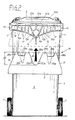
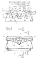
Figur 1- in rein schematischer Ansichtsdarstellung ein Müll-Entsorgungssystem, welchem als Systemglieder ein Müllsammelfahrzeug mit Hub-Kippvorrichtungen und Schüttungsaufnahmen sowie mehrere Ausführungsformen oder Bauarten von Müllgefäßen bzw. -Containern mit unterschiedlichem Fassungsvermögen zugeordnet ist,
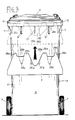
Figur 2- in vergrößertem Maßstab der untere, rechte Müllbehälter bzw. -container nach Fig. 1 in Zuordnung zu einer einen Greifer oder eine Greifschiene bildenden Schüttungsaufnahme einer Hub-Kippvorrichtung des Müllsammelfahrzeuges,
Figur 3- eine der Fig. 2 entsprechende Darstellung des unteren, linken Müllgefäßes aus Fig. 1,
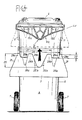
- Figur 4
- eine der Fig. 2 entsprechende Darstellung des oberen, rechten Müllgefäßes aus Fig. 1,
Figur 5- eine der Fig. 2 entsprechende Darstellung des oberen, linken Müllgefäßes aus Fig. 1,
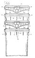
Figur 6- in schematischer Ansichtsdartstellung eine Stapelsäule aus mehreren leeren Müllbehältern bzw. -containern der in Fig. 1 unten gezeigten beiden Bauarten,
Figur 7- eine der Fig. 6 entsprechende Darstellung einer Stapelsäule aus Müllbehältern bzw. -containern in den aus Fig. 1 ersichtlichen, beiden oberen Bauarten,
Figur 8- in räumlicher Rückansicht eine der einen Greifer oder eine Greifschiene bildenden Schüttungsaufnahmen, wie sie den Hub-Kippvorrichtungen des Müllsammelfahrzeuges zugeordnet sind,
- Figur 9
- in Stirnansicht den oberen Teil eines Müllbehälters der Bauart nach Fig. 2, welcher über seine eine Aufnahmetasche bildende Schüttrandgestaltung mit einem einen Greifer oder eine Greifschiene bildenden Schüttungsaufnahme nach Fig. 8 in Eingriff gebracht ist,
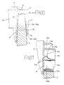
Figur 10- in vergrößertem Maßstab einen Schnitt entlang der Linie X-X in Fig. 9 und
Figur 11- in vergrößertem Maßstab einen Schnitt entlang der Linie XI-XI in Fig. 9.
- Figure 1
- in a purely schematic view representation, a waste disposal system, to which a waste collection vehicle with lifting and tipping devices and bulk receptacles as well as several embodiments or types of waste containers or containers with different capacities are assigned as system elements,
- Figure 2
- on an enlarged scale the lower right rubbish container or container according to FIG. 1 in association with a bed receptacle of a lifting and tipping device of the refuse collection vehicle forming a gripper or a gripping rail,
- Figure 3
- 1 corresponding representation of the lower, left garbage container from FIG. 1,
- Figure 4
- 1 corresponding representation of the upper right garbage container from FIG. 1,
- Figure 5
- 2 shows an illustration corresponding to FIG. 2 of the upper, left-hand waste container from FIG. 1,
- Figure 6
- a schematic view of a stack of several empty garbage containers or bins of the two types shown in FIG. 1,
- Figure 7
- 6 a representation of a stacking column of waste containers or containers corresponding to FIG. 6 in the two upper types shown in FIG. 1,
- Figure 8
- in a spatial rear view one of the bulk receptacles forming a gripper or a gripping rail, as they are assigned to the lifting and tilting devices of the refuse collection vehicle,
- Figure 9
- 2 is a front view of the upper part of a refuse container of the type according to FIG. 2, which is brought into engagement with a fill receptacle according to FIG.
- Figure 10
- on an enlarged scale a section along the line XX in Fig. 9 and
- Figure 11
- on an enlarged scale a section along the line XI-XI in Fig. 9th
In rein schematischer Darstellung ist aus Fig. 1 der Zeichnung ein Müll-Entsorgungssystem ersichtlich, welchem als Systemglieder Müllsammelfahrzeuge 1 mit Hub-Kippvorrichtungen 2 und daran montierten Schüttungsaufnahmen 3 sowie mehrere, bspw. vier, verschiedene Müllbehälter bzw. -container 4a, 4b, 4c, 4d angehören.In a purely schematic representation, a waste disposal system can be seen from FIG. 1 of the drawing, which comprises
Die Müllbehälter bzw. -container 4a und 4b gehören zu einer herkömmlichen älteren Bauart, während die Müllbehälter bzw. -container 4c und 4d einer neuen, verbesserten Bauart angehören. Die beiden Müllbehälter bzw. -container 4a und 4c haben untereinander ein übereinstimmendes, bspw. mittleres Füllvolumen, welches bspw. zwischen 0,12 und 0,24 m³ betragen kann, während die Müllbehälter bzw. -container 4b und 4d für ein kleineres Fassungsvermögen, bspw. von 0,08 m³ ausgelegt sind.The garbage containers or
Selbstverständlich können dem Müll-Entsorgungssystem aber auch noch Müllbehälter bzw. -container angehören, die für großes Füllvolumen, bspw. 0,36 m³ ausgelegt sind.Of course, the waste disposal system can also include waste containers or containers that are designed for large filling volumes, for example 0.36 m³.
Jede dem Müll-Entsorgungssystem angehörende Ausführung bzw. Bauart von Müllbehältern bzw. -Containern 4a bis 4d weist einen durch einen Klappdeckel 5 verschließbaren Behälter- bzw. Containerrumpf 6 auf und ist an letzterem auch noch mit einem Laufradpaar 7 versehen.Each version or type of waste container or
Der Behälter- bzw. Containerrumpf 6 jedes Müllbehälters bzw. -containers 4a bis 4d weist an seiner den Scharnieren für den Klappdeckel 5 gegenüberliegenden Vorderwand 8 eine Schüttrandgestaltung 9a oder 9b auf, die bspw. als Aufnahmetasche ausgeführt werden kann. Jede Schüttungsaufnahme 9a bzw. 9b bildet dabei einen Kupplungseingriff für die als Greifer oder Greifschiene ausgelegte Schüttungsaufnahme 3 einer Hub-Kippvorrichtung.The container or
Die Schüttrandgestaltungen 9a und 9b gehen zu den Seitenwänden des Behälter- bzw. Containerrumpfes 6 hin jeweils in den Versteifungskragen 10 über, welcher sich sowohl längs der Seitenwände als auch entlang der Rückwand des Behälter- bzw. -Containerrumpfes 6 im Bereich der Behälteröffnung erstreckt. Die Ausbildung des Versteifungskragens 10 kann herkömmlicher Art sein und wird daher im einzelnen hier nicht erläutert.The pouring
Erwähnt sei an dieser Stelle noch, daß bei allen Müllbehältern bzw. -containern 4a, 4b, 4c und 4d der Behälter- bzw. Containerrumpf 6 unterhalb seines Versteifungskragens 10 - mindestens an seinen Seitenwänden - noch Stapelrippen bzw. -stege 11 trägt, die ein mehrfaches Ineinandersetzen leerer Müllbehälter bzw. -container 4a und 4c bzw. 4b und 4d gleichen Fassungsvermögens zum Zwecke der Bildung von raumsparenden Stapelsäulen ermöglichen, sofern an diesen die Laufradpaare 7 entfernt bzw. noch nicht angebracht sind.At this point it should also be mentioned that in all garbage containers or
Obwohl die Schüttrandgestaltung 9a an den beiden Müllbehältern bzw. -containern 4a und 4b eine baulich übereinstimmende Grundausführung hinsichtlich der Profilierung und Abmessung ihrer Aufnahmetasche haben, weisen sie jedoch, bedingt durch das unterschiedliche Fassungsvermögen ihres Behälter- bzw. Containerrumpfes 6, gewisse Unterschiedsmerkmale auf. So ist die Schüttrandgestaltung 9a' des Müllbehälters bzw. -containers 4a mit Einzelrippen bzw. -stegen 12' ausgestattet, die eine andere Anordnung und Ausbildung aufweisen als die Einzelrippen bzw. -stege 12'' am Müllbehälter bzw. -container 4b.Although the pouring
In jedem Falle dienen jedoch die Einzelrippen bzw. -stege 12' und 12'' einer Absteifung und Stabilisierung der jeweiligen Schüttrandgestaltung 9a' bzw. 9a'' gegen den Behälter- bzw. Containerrumpf 6. Durch die Einzelrippen bzw. -stege 12' bzw. 12'' wird die bspw. als Aufnahmetasche ausgeführte Schüttrandgestaltung 9a' oder 9a'' in mehrere längs der Vorderseite 8 des Behälter- bzw. Containerrumpfes 6 vorgesehene Taschenabschnitte unterteilt.In any case, however, the individual ribs or webs 12 'and 12' 'serve to stiffen and stabilize the respective pouring
Die bspw. als Aufnahmetaschen ausgeführten Schüttrandgestaltungen 9b an den Müllbehältern bzw. -containern 4c und 4d kann grundsätzlich übereinstimmend ausgeführt sein, wobei sich Unterschiede lediglich hinsichtlich ihrer Baulänge ergeben, die wiederum dadurch bestimmt wird, daß die Behälter bzw. Containerrümpfe 6 wegen ihres unterschiedlichen Fassungsvermögens bei etwa gleicher Bauhöhe unterschiedliche Querschnitte erhalten müssen.The pouring
Die Auslegung der als Aufnahmetaschen ausgeführten Schüttrandgestaltungen 9b für die Müllbehälter bzw. -container 4c und 4d ergibt sich - in gegenüber der Darstellung von Fig. 1 vergrößertem Maßstab - insbesondere aus den Fig. 2, 4 sowie 9 bis 11 der Zeichnung. Sie ist aber darüber hinaus auch noch den Fig. 6 und 7 der Zeichnung entnehmbar.The design of the pouring
Fig. 3 der Zeichnung zeigt in vergrößertem Maßstab die Ausbildungsmerkmale der Schüttrandgestaltung 9a' des Müllbehälters bzw. -containers 4a nach Fig. 1, während, ebenfalls in größerem Maßstab, die Schüttrandgestaltung 9a'' des Müllbehälters bzw. -containers 4b nach Fig. 1 in Fig. 5 wiedergegeben ist. Aus Fig. 6 gehen wiederum auch Ausbildungsmerkmale der Schüttrandgestaltung 9a' und aus Fig. 7 auch Merkmale der Schüttrandgestaltung 9a'' nach Fig. 1 hervor.3 of the drawing shows, on an enlarged scale, the design features of the pouring
Schließlich ist in Fig. 8 der Zeichnung in ausführlicher räumlicher Rückansicht die Ausbildung einer als Greifer oder Greifschiene wirksamen Schüttungsaufnahme 3 zu sehen, wie sie an den Hub-Kippvorrichtungen 2 der Müllsammelfahrzeuge 1 vorgesehen sind, um die zeitweilige Kupplungsverbindung mit den verschiedenen Schüttrandgestaltungen 9a bzw. 9a', 9a'' und 9b der innerhalb des Müll-Entsorgungssystems gleichzeitig benutzbaren Müllbehälter bzw. -container 4a, 4b, 4c und 4d zu ermöglichen.Finally, in FIG. 8 of the drawing, in a detailed spatial rear view, the formation of a
Das besondere Kennzeichnungsmerkmal der Schüttrandgestaltung 9b an der Vorderwand 8 der Müllbehälter 4c und 4d nach Fig. 1 liegt darin, daß dort an jedem Behälter- bzw. Containerrumpf 6 ein mittleres, also auf der vertikalen Längsmittelebene gelegenes und sich nach unten etwa dreieckförmig verjüngendes Rippen- bzw. Stegsystem 13 vorgesehen ist, welches einen Stütz- und Zentriereingriff 14 für die an den Hub-Kippvorrichtungen 2 des Müllsammelfahrzeugs 1 befindlichen Schüttungsaufnahmen 3 bildet.The special characteristic of the design of the pouring
Das Rippen- bzw. Stegsystem 13 dieses Stütz- und Zentriereingriffs 14 ist dabei, wie insbesondere die Fig. 11 der Zeichnung erkennen läßt, unmittelbar einstückig an die Vorderwand 8 des Behälter- bzw. Containerrumpfes 6 angeformt, und zwar so, daß es im wesentlichen quer von der Ebene der Vorderwand 8 absteht.The rib or
Gebildet wird das Rippen- bzw. Stegsystem 13 des Stütz- und Zentriereingriffs 14 dabei von einer seine Dreiecksform eingrenzenden Umfassungsrippe 13a sowie von einer Vielzahl von Aussteifungs- bzw. Stabilisierungsstegen 13b, welche -gewissermaßen netzartig - innerhalb der Umfassungsrippe 13a verteilt angeordnet sind.The rib or
Nach links und nach recht schließt sich an den Stütz- und Zentriereingriff 14 mit Abstand von der Vorderwand 8 des Behälter- bzw. Containerrumpfes 6 jeweils ein Wandabschnitt 15a bzw. 15b an, wobei diese beiden Wandabschnitte 15a und 15b jeweils zueinander spiegelbildlich ausgebildet und symmetrisch zur Längsmittelebene durch den Stütz- und Zentriereingriff 14 angeordnet sind.To the left and to the right, the support and centering
Diese Wandabschnitte 15a und 15b schließen sich dabei jeweils nach unten an den üblicherweise um die Einfüllöffnung des Behälter- bzw. Containerrumpfes 6 herum verlaufenden Versteifungskragen 10 an, der unterseitig eine Stabilisierungsverrippung 16 enthält, wie das deutlich in Fig. 10 zu sehen ist.These
Jeder der beiden Wandabschnitte 15a und 15b ist außenseitig noch mit über seine gesamte Fläche verteilt angeordneten, bspw. senkrecht verlaufenden, Versteifungsrippen 17 versehen und ihre untere Begrenzungsrippe 18 hat einen solchen, bspw. leicht gekrümmten Verlauf, daß die beiden Wandabschnitte 15a und 15b eine etwa flach-dreieckförmig nach unten verjüngte Begrenzung erhalten, die zu den Seitenwänden hin in Höhe der Unterkante des Versteifungskragens 10 ausläuft.Each of the two
Zwischen der Vorderwand des Behälter- bzw. Containerrumpfes 6 und jedem der beiden Wandabschnitte 15a und 15b wird seitlich neben dem Stütz- und Zentriereingriff 16 ein nach unten offener Aufnahmetaschen-Abschnitt 19a bzw. 19b der Schüttrandgestaltung 9b ausgebildet, in den die Schüttungsaufnahme 3 einer Hub-Kippvorrichtung 2 eingefahren werden kann (Fig. 10).Between the front wall of the container or
Für die insbesondere aus den Fig. 2, 4 und 9 bis 11 der Zeichnung ersichtliche Schüttrandgestaltung 9b an den Behälter- bzw. Containerrümpfen 6 der Müllbehälter bzw. -container 4c und 4d hat es sich auch als wichtig erwiesen, daß die abwärts gerichteten Dreieckspitzen sowohl des Stütz-und Zentriereingriffs 14 als auch der Wandabschnitte 15a, 15b etwas oberhalb der unteren Enden der am Außenumfang des Behälter- bzw. Containerrumpfes ausgebildeten Stapelstege 11 liegen. Hierdurch wird, wie die Fig. 6 und 7 ausweisen, sichergestellt, daß bei einem säulenartigen Ineinandersetzen mehrerer leerer Müllbehälter bzw. -container das Auftreffen dieser Dreieckspitzen auf den Versteifungskragen 10 des nächstunteren Müllbehälters bzw. -containers vermieden ist.For the particular apparent from FIGS. 2, 4 and 9 to 11 of the drawing, the pouring
Damit Müllbehälter bzw. -container 4c und 4d mit der besonders vorteilhaften Schüttrandgestaltung bei Bedarf problemlos in ein Müll-Entsorgungssystem eingegliedert werden können, dem zuvor nur Müllbehälter bzw. -container 4a und 4b mit Schüttrandgestaltungen 9a' und 9a'' als Systemglieder angehörten, wird die Benutzung von als Greifer bzw. Greifschiene gestalteten Schüttungsaufnahmen 3 an den Hub-Kippvorrichtungen 2 vorgesehen, die mit jeder der Schüttrandgestaltungen 9a', 9a'' und 9b kompatibel ist.So that garbage containers or
Eine solchermaßen ausgeführte, einen Greifer oder eine Greifschiene bildende Schüttungsaufnahme 3 wird in räumlicher Rückansicht in Fig. 8 der Zeichnung gezeigt, ist aber in schematisch vereinfachter Vorderansicht jeweils auch in den Fig. 2 bis 5 und 9 der Zeichnung zu sehen.A
Für die Kompatibilität der Schüttungsaufnahme 3 mit jeder der Schüttrandgestaltungen 9a bzw. 9a', 9a'' und 9b ist eine besondere Ausbildung an dem mit den verschiedenen Schüttrandgestaltungen in Kupplungseingriff bzw. Wirkverbindung tretenden, vertikalen Randbereich 20 und horizontalen Randbereich 21 wichtig.For the compatibility of the
Aus Fig. 8 geht bspw. hervor, daß die als Greifer bzw. Greifschiene gestaltete Schüttungsaufnahme 3 der (nicht gezeigten) Hub-Kippvorrichtung über ihren vertikalen Randbereich 20 hinweg mit einer parallel zu ihrer Hauptebene orientierten Verzahnungskontur 22 ausgestattet ist. Darüber hinaus weist die Schüttungsaufnahme 3 aber auch über ihren horizontalen Randbereich 21 hinweg noch eine quer zur Hauptebene orientierte Verzahnungskontur 23 auf.From FIG. 8 it can be seen, for example, that the
Wichtig für die Ausbildung der Schüttungsaufnahme 3 ist dabei, daß bei der Verzahnungskontur 22 die im wesentlichen quer zur Hauptebene gerichteten Kopfflächen auf einer gemeinsamen Geraden liegen und daß auch die etwa parallel zur Hauptebene gerichteten Stirnflächen der quer zur Hauptebene orientierten Verzahnungskontur 23 eine gemeinsame Gerade 27 haben.It is important for the formation of the
Die in Richtung der Haupt ebene der Schüttungsaufnahme 3 orientierte Verzahnungskontur 22 besteht beim dargestellten Ausführungsbeispiel jeweils aus vier trapezförmig begrenzten Zähnen 28a und 28b und drei Zahnlücken 29a und 29b. Die beiden äußeren Zähne 28a sind dabei in ihrer Ausführung etwas schmaler gestaltet als die beiden mittleren Zähne 28b. Die beiden äußeren Zahnlücken 29a haben jeweils übereinstimmende Trapezform, während die mittlere Zahnlücke 29b wenigstens annähernd eine nach abwärts divergierende Dreiecksform hat, welche an die Umrißkontur der Stütz- und Zentriereingriffe 14 der Schüttrandgestaltung 9b für die Müllbehälter bzw. -container 4c und 4d angepaßt ist.The
Erkennbar ist nicht nur aus Fig. 8, sondern auch aus den Fig. 2 bis 5, daß die mittlere Zahnlücke 29b, gemessen von den auf der gemeinsamen Geraden 25 liegenden Kopfflächen 24 aus, eine Tiefe hat, die sich über den gesamten vertikalen Randbereich 20 erstreckt. Sie entspricht dabei einem Mehrfachen, z.B. dem Drei- bis Vierfachen der Tiefe 30 für die beiden äußeren Zahnlücken 29a und 29b.It can be seen not only from FIG. 8 but also from FIGS. 2 to 5 that the
Erwähnenswert ist noch, daß die äußere Trapezflanke 31 der beiden äußeren Zähne 28a sich mit gleichbleibender Schräglage wenigstens annähernd über die ganze Höhe der Schüttungsaufnahme 3 erstreckt und daß die größte Breite 32 der mittleren Zahnlücke 29b wesentlich größer als die größte Breite 33 der beiden äußeren Zahnlücken 29a bemessen ist, bspw. etwa dem Zweifachen derselben entspricht.It is also worth mentioning that the outer
Andererseits wird die quer zur Hauptebene der Schüttungsaufnahme 3 orientierte Verzahnungskontur 23 jeweils von vier Zähnen 34a und 34b und vier Lücken 35a und 35b begrenzt. Die beiden äußeren Lücken 35a derselben sind dabei jeweils im Bereich einer äußeren Zahnlücke 29a der anderen Verzahnungskontur 22 angeordnet, während die beiden inneren Lücken 35b an die Flanken der mittleren Zahnlücke 29b der anderen Verzahnungskontur 22 anschließen.On the other hand, the
Die beiden äußeren Lücken 35a der Verzahnungskontur 23 weisen jeweils etwa die Form einer von unten nach oben pyramidenartig divergierenden Nut auf, während die beiden mittleren Lücken 35b aus Flankeneinschnitten an der mittleren Zahnlücke der anderen Verzahnungskontur 22 bestehen. Dabei haben die mittleren Lücken in Richtung der Hauptebene der Schüttungsaufnahme 3 die Umrißform eines mit seiner Spitze nach oben gerichteten, rechtwinkligen Dreiecks, während sie quer zur Hauptebene der Schüttungsaufnahme 3 ein mit seiner Spitze nach unten weisendes, rechtwinkliges Dreieck bestimmen.The two
Erkennbar ist aus der Zeichnung auch noch, daß jeweils die innere Flanke der beiden äußeren Lücken 35a in geradliniger Verlängerung der inneren Flanke einer äußeren Zahnlücke 29a der anderen Verzahnungskontur 22 angeordnet ist.It can also be seen from the drawing that the inner flank of the two
Von Vorteil ist es, wenn die Gesamtbreite 36 der Schüttungsaufnahme 3 im Bereich ihrer in Richtung der Hauptebene orientierten Verzahnungskontur 22 auf die Baubreite der Schüttrandgestaltung 9a' bzw. 9b von Müllbehältern bzw. -containern 4a und 4c mit einem mittleren Fassungsvermögen von bspw. 0,12 bis 0,24 m³ abgestimmt wird. Die äußeren Zahnlücken 29a dieser Verzahnungskontur 22 weisen dabei jeweils eine Öffnungsweite auf, die mindestens dem Profilquerschnitt des an die Schüttrandgestaltung 9a' und 9b entlang den Seitenwänden des Behälter- bzw. Containerrumpfes 6 anschließenden Versteifungskragens 10 entspricht.It is of advantage if the
Der Abstand 37 zwischen der Außenflanke eines äußeren Zahnes 28a und der Innenflanke der dem anderen äußeren Zahn 28a benachbarten äußeren Zahnlücke 29a wird in vorteilhafter Weise auf das Lichtmaß der Schüttrandgestaltung 9a'' bzw. 9b an einem Müllbehälter bzw. -container 4b bzw. 4d mit kleinem Fassungsvermögen, von bspw. 0,08 m³, abgestimmt.The
Auch der Abstand 38 zwischen den Außenflanken der beiden äußeren Zahnlücken 29a sollte auf das Lichtmaß der Schüttrandgestaltung 9a'' bzw. 9b an einem Müllbehälter bzw. -container 4b bzw. 4d mit kleinem Fassungsvermögen von bspw. 0,08 m³ abgestimmt sein. Die Fig. 2, 4 und 9 der Zeichnung machen deutlich, daß beim Einfahren der Schüttungsaufnahme 3 in die Schüttrandgestaltung 9b die mittlere Zahnlücke 29b der Verzahnungskontur 22 am Stütz- bzw. Zentriereingriff 14 angreift, während die daneben gelegenen Zähne 28a, 28b und Zahnlücken 29a in die jeweils von den Wandabschnitten 15a und 15b nach außen begrenzten Aufnahmetaschen-Abschnitte 19a und 19b eintauchen. Dabei kommen die Kopfflächen 24 der Zähne 28a und 28b an der Stabilisierungsverrippung 16 zur Anlage, die sich jeweils oberhalb der Aufnahmetaschen-Abschnitte 19a und 19b innerhalb des Versteifungskragens 10 befinden.The
Die aus dem mittleren Stütz- und Zentriereingriff 14, den beiden Wandabschnitten 15a, 15b und den Aufnahmetaschen-Abschnitten 19a und 19b gebildete Schüttrandgestaltung 9b bietet dabei den Müllbehältern bzw. -containern 4c und 4d jeweils einen sicheren und stabilen Halt an der Schüttungsaufnahme 3 während der gesamten Arbeitsbewegung der Hub-Kippvorrichtung 2.The pouring
Die Zahnlücken 29a und 29b der Verzahnungskontur 22 wie auch die Lücken 35a und 35b der Verzahnungskontur 23 haben beim Zusammenwirken der Schüttungsaufnahme 3 mit der Schüttrandgestaltung 9b der Müllbehälter bzw. -container 4c und 4d keine funktionelle Bedeutung.The
Funktionell wichtig sind jedoch die Zahnlücken 29a der Verzahnungskontur 22 sowie die Zahnlücken 35a und 35 der Verzahnungskontur 23 für den Einsatz der Schüttungsaufnahme 3 in Verbindung mit Müllbehältern bzw. -containern 4a und 4b, die eine Schüttrandgestaltung 9a bzw. 9a' und 9a'' aufweisen, wie das durch die Fig. 3 und 5 der Zeichnung verdeutlicht wird.Functionally important, however, are the
Bei der Schüttrandgestaltung 9a' nach Fig. 3 kommt beim Einfahren der Schüttungsaufnahme 3 die Verzahnungskontur 22 über ihre vier Zähne 28a und 28b in Kupplungseingriff, während die mittlere Zahnlücke 29b einen Freiraum für das Eintauchen der mittleren Einzelrippe bzw. des mittleren Einzelsteges 12' bildet.3, the
Als Aufnahmen für die beiden äußeren Einzelrippen 12' wirken in diesem Falle die beiden äußeren Lücken 35a der anderen Verzahnungskontur 23. Beim Einfahren der Schüttungsaufnahme 3 in die Schüttrandgestaltung 9a'' des Müllbehälters bzw. -containers 4b nach Fig. 5 ist es notwendig, die Schüttungsaufnahme 3 mit seitlicher Versetztlage anzusetzen. Die Versetztlage ist dabei solcherart, daß einer der äußeren Zähne 28a der Verzahnungskontur 22 seitlich außerhalb des Versteifungskragens zu liegen kommt, so daß letzterer in die benachbarte, äußere Zahnlücke 29a eintaucht. Die übrigen drei Zähne 28a und 28b kommen hingegen in die Schüttrandgestaltung 9a'' zum Eingriff, und zwar derart, daß die linke Einzelrippe bzw. der linke Einzelsteg 12'' der Schüttrandgestaltung 9a'' in eine, und zwar die linke Lücke 35b der Verzahnungskontur 23 eintaucht, während die andere Einzelrippe bzw. der andere Einzelsteg 12'' in der rechten äußeren Lücke 35a dieser Verzahnungskontur 23 zu liegen kommt.In this case, the two
Durch die Ausstattung der den Hub-Kippvorrichtungen 2 zuzuordnenden Schüttungsaufnahme 3 mit den beiden in zueinander rechtwinkligen Ebenen angeordneten Verzahnungskonturen 22 und 23 wird auf einfache Art aund Weise gewährleistet, daß diese Schüttungsaufnahme 3 mit einer größeren Anzahl verschiedener Schüttrandgestaltungen 9a bzw. 9a', 9a'' und 9b von Müllbehältern bzw. -containern 4a bis 4d kompatibel ist. Trotz gleichzeitiger Benutzung von Müllbehältern bzw. -containern 4a bis 4d mit verschiedenen Schüttrandgestaltungen 9a bzw. 9a', 9a'' und 9b kann daher das gesamte Müll-Entsorgungssystem rationell und problemlos betrieben werden.By equipping the
Die Benutzbarkeit der mit den beiden Verzahnungskonturen 22 und 23 versehenen Schüttungsaufnahmen ist insbesondere dadurch erreichbar, daß bei den neu konzipierten Müllbehältern bzw. -containern 4c und 4d die Schüttrandgestaltung 9b mit dem sich nach unten etwa dreieckförmig verjüngenden Stütz- und Zentriereingriff 14 versehen ist, der in die hierzu passend konturierte, mittlere Zahnlücke 29b der Verzahnungs-Kontur 22 in der Schüttungsaufnahme 3 eintauchen kann.The usability of the fill receptacles provided with the two
Abschließend wird nur noch darauf hingewiesen, daß an den neu konzipierten Müllbehältern bzw. -containern 4c und 4d deren die Aufnahmetasche 19a, 19b bildende Schüttrandgestaltung 9b auch eine gegenüber den Darstellungen der Zeichnung, und zwar insbesondere der Fig. 2, 4 und 9 bis 11 abgewandelte Ausführung erhalten kann, sofern die als Greifer bzw. Greifschiene gestaltete Schüttungsaufnahme 3 der Hub-Kippvorrichtung 2 eine hieran angepaßte Ausführung erhält.Finally, it is only pointed out that the newly designed refuse containers or
So ist es ohne weiteres möglich, an den Müllbehältern bzw. -containern 4c und 4d statt des mittleren Stütz- und Zentriereingriffs 14 zwei symmetrisch aus der Mitte versetzt angeordnete Stütz- und Zentriereingriffe 14 mit sich nach unten etwa dreieckförmig verjüngender Gestalt vorzusehen.Thus, it is readily possible to provide on the garbage containers or
In diesem Falle wäre es natürlich notwendig, daß an der als Greifer bzw. Greifschiene gestalteten Schüttungsaufnahme 3 der Hub-Kippvorrichtung 2 die beiden äußeren Zahnlücken 29a anstelle der Trapezform ebenfalls eine Dreiecksform erhalten, welche der Dreiecksform zumindest ähnlich ist, wie sie nach der Zeichnung die mittlere Zahnlücke 29b aufweist.In this case, it would of course be necessary for the two
Im Bereich der in der Zeichnung gezeigten, mittleren Zahnlücke 29b müßte die Schüttungsaufnahme 3 lediglich so gestaltet sein, daß dort die quer zur Haupt ebene orientierte Verzahnungskontur 23, 35a, 35b eine beschädigungsfreie Aufnahme der Einzelrippen bzw. -stege 12' bzw. 12'' der herkömmlichen, älteren Bauart von Müllbehältern bzw. -containern 4a und 4b ermöglicht. Hierzu reicht es in der Regel aus, an der Schüttungsaufnahme 3 den gesamten Bereich zwischen den beiden mittleren Lücken 35b quer zur Hauptebene der Schüttungsaufnahme 3 in Form eines mit seiner Spitze nach unten weisenden, rechtwinkligen Dreiecks freizumachen und gegebenenfalls statt der dreieckförmigen mittleren Zahnlücke 29b einen relativ schmalen Schlitzabschnitt vorzusehen.In the area of the
Claims (15)
dadurch gekennzeichnet,
daß die als Greifer bzw. Greifschiene geestaltete Schüttungsaufnahme (3) der Hub-Kippvorrichtung (2) entlang ihrem der Aufnahmetasche bzw. Schüttrandgestaltung (9a', 9a'' und 9b) der Müllbehälter bzw. -container (4a bis 4d) zugeordneten Randbereich (20) mit sowohl parallel als auch quer zu ihrer Haupt ebene orientierten Verzahnungskonturen (22 und 23) ausgestattet ist,
wobei einerseits die im wesentlichen quer zur Hauptebene der Schüttungsaufnahme (3) gerichteten Kopfflächen (24) der parallel zu dieser Hauptebene orientierten Verzahnungskontur (22) und andererseits die etwa parallel zur Hauptebene gerichteten Stirnflächen (26) der quer hierzu orientierten Verzahnungskontur (23) jeweils auf einer gemeinsamen Geraden (25 bzw. 27) liegen,
während die Begrenzungsflächen der jeweils von diesen Geraden ( 25 bzw. 27) zurückspringenden Zahnlücken (29a, 29b bzw. 35a, 35b) eine Formgebung haben, welche auf die Lage der Einzelrippen bzw. -stege (12' bzw. 12'') und/oder der Rippen- bzw. Stegsysteme (13, 14) an verschiedenen Müllbehältern bzw. -containern (4a bis 4d) abgestimmt ist.Garbage disposal system, consisting of garbage containers or containers, at least one garbage collection vehicle and a lifting and tipping device arranged on the latter, which is temporarily formed by a bulk holder, for example a gripper or a gripping rail, with a pouring rim design of the garbage container or -container can be coupled, which is located on the front wall of the container or container body opposite the hinges for a hinged lid, the receiving pocket or pouring rim design in the engagement area of the gripper or the gripping rail or the bulk receiving means by individual ribs or webs or by Rib or web systems in several along the front wall of the container or. The container body is divided into pocket sections,
characterized,
that the bed receptacle (3) of the lifting and tilting device (2), designed as a gripper or gripping rail, along its edge area (4a to 4d) associated with the receptacle pocket or pouring rim design (9a ', 9a''and 9b) 20) is equipped with toothing contours (22 and 23) oriented both parallel and transversely to their main plane,
on the one hand, the head surfaces (24) of the toothing contour oriented parallel to this main plane and oriented essentially transversely to the main plane of the bed receptacle (3) (22) and, on the other hand, the end faces (26) of the toothing contour (23) oriented approximately parallel to the main plane each lie on a common straight line (25 or 27),
while the boundary surfaces of the tooth gaps (29a, 29b or 35a, 35b) that spring back from these straight lines (25 or 27) have a shape that corresponds to the position of the individual ribs or webs (12 'or 12'') and / or the rib or web systems (13, 14) on different waste containers or containers (4a to 4d) is coordinated.
dadurch gekennzeichnet,
daß die in Richtung der Hauptebene der Schüttungsaufnahme (3) orientierte Verzahnungskontur (22) aus vier trapezförmig begrenzten Zähnen (28a, 28b) und drei Zahnlücken (29a, 29b) besteht, wobei die beiden äußeren Zahnlücken (29a) ebenfalls Trapezform haben, während die mittlere Zahnlücke (29b) wenigstens annähernd eine Dreiecksform aufweist.Garbage disposal system according to claim 1,
characterized,
that the toothing contour (22) oriented in the direction of the main plane of the bed holder (3) consists of four trapezoidally delimited teeth (28a, 28b) and three tooth gaps (29a, 29b), the two outer tooth gaps (29a) also having a trapezoidal shape, while the middle tooth gap (29b) has at least approximately a triangular shape.
dadurch gekennzeichnet,
daß die mittlere Zahnlücke (29b) eine Tiefe (20) hat, die einem Mehrfachen, z.B. dem Drei- bis Vierfachen der Tiefe (30) jeder äußeren Zahnlücke (29a) entspricht.Garbage disposal system according to one of claims 1 and 2,
characterized,
that the middle tooth gap (29b) has a depth (20) which corresponds to a multiple, for example three to four times the depth (30) of each outer tooth gap (29a).
dadurch gekennzeichnet,
daß die Tiefe beider äußeren Zahnlücken (29a) übereinstimmt.Waste disposal system according to one of claims 1 to 3,
characterized,
that the depth of both outer tooth gaps (29a) matches.
dadurch gekennzeichnet,
daß die äußere Trapezflanke (31) der beiden äußeren Zähne (28a) sich mit gleichbleibender Schräglage wenigstens annähernd über die ganze Höhe der Schüttungsaufnahme (3) erstreckt.Garbage disposal system according to one of claims 1 to 4,
characterized,
that the outer trapezoidal flank (31) of the two outer teeth (28a) extends at least approximately over the entire height of the bed receptacle (3) with a constant inclined position.
dadurch gekennzeichnet,
daß die größte Breite (32) der mittleren Zahnlücke (29b) wesentlich größer als die größte Breite (33) der beiden äußeren Zahnlücken (29a) bemessen ist, z.B. etwa dem Zweifachen derselben entspricht.Garbage disposal system according to one of claims 1 to 5,
characterized,
that the greatest width (32) of the middle tooth gap (29b) is substantially larger than the greatest width (33) of the two outer tooth gaps (29a), for example corresponds approximately to twice this.
dadurch gekennzeichnet,
daß die quer zur Hauptebene der Schüttungsaufnahme (3) orientierte Verzahnungskontur (23) von vier Zähnen (34a, 34b) und vier Lücken (35a und 35b) begrenzt ist und dabei die beiden äußeren Lücken (35a) jeweils im Bereich einer äußeren Zahnlücke (29a) der anderen Verzahnungskontur (22) liegen, während die beiden inneren Lücken (35b) an die Flanken der mittleren Zahnlücke (29b) der anderen Verzahnungskontur (22) anschließen.Garbage disposal system according to one of claims 1 to 6,
characterized,
that the toothing contour (23) oriented transversely to the main plane of the bed receptacle (3) is delimited by four teeth (34a, 34b) and four gaps (35a and 35b) and the two outer gaps (35a) each in the area of an outer tooth gap (29a ) of the other toothing contour (22), while the two inner gaps (35b) connect to the flanks of the middle tooth gap (29b) of the other toothing contour (22).
dadurch gekennzeichnet,
daß die beiden äußeren Lücken (35a) jeweils etwa die Form einer von unten nach oben pyramidenartig divergierenden Nut aufweisen, während die beiden mittleren Lücken (35b) aus Flankeneinschnitten an der mittleren Zahnlücke (29b) der anderen Verzahnungskontur (22) bestehen, die in Richtung der Hauptebene der Schüttungsaufnahme (3) die Umrißform eines mit seiner Spitze nach oben gerichteten, rechtwinkligen Dreiecks begrenzen, während sie quer zur Haupt ebene der Schüttungsaufnahme (3) ein mit seiner Spitze nach unten weisendes, rechtwinkliges Dreieck bestimmen.Garbage disposal system according to one of claims 1 to 7,
characterized,
that the two outer gaps (35a) each have approximately the shape of a groove which diverges from bottom to top in a pyramid-like manner, while the two middle gaps (35b) consist of flank incisions on the middle tooth gap (29b) of the other toothing contour (22), which face in the direction the main plane of the fill receptacle (3) has the outline shape of one with its tip pointing upwards, limit the right-angled triangle, while defining a right-angled triangle with its tip pointing downwards, transversely to the main plane of the bed holder (3).
dadurch gekennzeichnet,
daß jeweils die innere Flanke der beiden äußeren Lücken (35a) in geradliniger Verlängerung der inneren Flanke einer äußeren Zahnlücke (29a) der anderen Verzahnungskontur (22) angeordnet ist.Garbage disposal system according to one of claims 1 to 8,
characterized,
that the inner flank of the two outer gaps (35a) is arranged in a straight line extension of the inner flank of an outer tooth gap (29a) of the other toothing contour (22).
dadurch gekennzeichnet,
daß die Gesamtbreite (36) der Schüttungsaufnahme (3) im Bereich ihrer in Richtung der Haupt ebene orientierten Verzahnungskontur (22) auf die Baubreite der Schüttrandgestaltung (9a' und 9b) von Müllbehältern bzw. -containern (4a und 4c) mit mittlerem Fassungsvermögen von z.B. 0,12 bis 0,24 m³ abgestimmt ist, während die äußeren Zahnlücken (29a) dieser Verzahnungskontur (22) jeweils eine Öffnungsweite (33) aufweisen, die mindestens dem Profilquerschnitt des an die Schüttrandgestaltung (9a', 9a'' und 9b) entlang den Seitenwänden des Behälter-bzw. Containerrumpfes (6) anschließenden Versteifungskragens (10) entspricht.Garbage disposal system according to one of claims 1 to 9,
characterized,
that the total width (36) of the bed receptacle (3) in the area of their toothing contour (22) oriented in the direction of the main plane to the overall width of the pouring rim design (9a 'and 9b) of refuse containers or containers (4a and 4c) with a medium capacity of For example, 0.12 to 0.24 m³ is matched, while the outer tooth gaps (29a) of this toothing contour (22) each have an opening width (33) that corresponds at least to the profile cross section of the design of the pouring rim (9a ', 9a''and 9b) along the side walls of the container or. Container hull (6) adjoining stiffening collar (10) corresponds.
dadurch gekennzeichnet,
daß der Abstand (37) zwischen der Außenflanke eines äußeren Zahnes (28a) und der Innenflanke der dem anderen äußeren Zahn (28a) benachbarten äußeren Zahnlücke (29a) auf das Lichtmaß der Schüttrandgestaltung (9a'' und 9b) an einem Müllbehälter bzw. -container (4b und 4d) mit kleinerem Fassungsvermögen von bspw. 0,08 m³ abgestimmt ist.Garbage disposal system according to one of claims 1 to 10,
characterized,
that the distance (37) between the outer flank of an outer tooth (28a) and the inner flank of the outer tooth gap (29a) adjacent to the other outer tooth (28a) depends on the light dimension of the pouring rim design (9a '' and 9b) on a waste container or container (4b and 4d) with a smaller capacity of, for example, 0.08 m³.
dadurch gekennzeichnet,
daß auch der Abstand (38) zwischen den Innenflanken der beiden äußeren Zahnlücken (29a) auf das Lichtmaß der Schüttrandgesetaltung (9a'' und 9b) an einem Müllbehälter bzw. -container (4b bzw. 4d) mit kleinem Fassungsvermögen von bspw. 0,08 m³ abgestimmt ist.Garbage disposal system according to one of claims 1 to 11,
characterized,
that the distance (38) between the inner flanks of the two outer tooth gaps (29a) to the light dimension of the pouring rim design (9a '' and 9b) on a waste container or container (4b or 4d) with a small capacity of 0, for example, 08 m³ is coordinated.
gekennzeichnet durch
Müllbehälter bzw. -container (4c und 4d), deren die Aufnahmetasche (19a, 19b) bildende Schüttrandgestaltung (9b) ein mittleres, sich nach unten etwa dreieckförmig verjüngendes Rippen- bzw. Stegsystem (13) aufweist, das einen Stütz- und Zentriereingriff (14) für die mittlere etwa dreieckförmige Zahnlücke (29b) der an der Schüttungsaufnahme (3) der Hub-Kippvorrichtung (2) vorgesehenen Verzahnungskontur (22) bildet.Garbage disposal system according to one of claims 1 to 12,
marked by
Garbage containers or containers (4c and 4d), the pouring rim design (9b) of which forms the receiving pocket (19a, 19b) has a central rib or web system (13) which tapers downward in an approximately triangular shape and which supports and centers ( 14) for the central approximately triangular tooth gap (29b) forms the toothing contour (22) provided on the bed receptacle (3) of the lifting and tilting device (2).
dadurch gekennzeichnet,
daß die äußere Wand (15a, 15b) der die Aufnahmetasche (19a, 19b) bildenden Schüttrandgestaltung (9b) eine ebenfalls etwa flach-dreieckförmig nach unten verjüngte Begrenzung (18) aufweist und dabei außenseitig mit über die gesamte Fläche verteilt anageordneten Versteifungsrippen bzw. -stegen (17) versehen ist.Garbage disposal system according to claim 13,
characterized,
that the outer wall (15a, 15b) of the pouring rim design (9b) forming the receiving pocket (19a, 19b) has a delimitation (18) that also tapers downward in a somewhat flat-triangular manner and, on the outside, with stiffening ribs arranged over the entire surface or - webs (17) is provided.
der Ansprüche 13 und 14,
dadurch gekennzeichnet,
daß die abwärts gerichteten Dreieckspitzen des Stütz- und zentriereingriffs (14) und der wandabschnitte (15a, 15b) der Schüttrandgestaltung (9b) bzw. der Aufnahmetasche (19a, 19b) oberhalb der unteren Enden von am Außenumfang des Behälter- bzw. Containerrumpfes (6) ausgebildeten Stapelstegen (11) liegen.Garbage disposal system after one
of claims 13 and 14,
characterized,
that the downward triangular tips of the support and centering engagement (14) and the wall sections (15a, 15b) of the pouring rim design (9b) or the receiving pocket (19a, 19b) above the lower ends of the outer circumference of the container or container body (6 ) trained stacking webs (11).
Priority Applications (1)
| Application Number | Priority Date | Filing Date | Title |
|---|---|---|---|
| AT91104118T ATE84274T1 (en) | 1990-03-21 | 1991-03-16 | WASTE DISPOSAL SYSTEM. |
Applications Claiming Priority (2)
| Application Number | Priority Date | Filing Date | Title |
|---|---|---|---|
| DE4009060A DE4009060A1 (en) | 1990-03-21 | 1990-03-21 | MUELL DISPOSAL SYSTEM |
| DE4009060 | 1990-03-21 |
Publications (2)
| Publication Number | Publication Date |
|---|---|
| EP0448002A1 true EP0448002A1 (en) | 1991-09-25 |
| EP0448002B1 EP0448002B1 (en) | 1993-01-07 |
Family
ID=6402726
Family Applications (1)
| Application Number | Title | Priority Date | Filing Date |
|---|---|---|---|
| EP91104118A Expired - Lifetime EP0448002B1 (en) | 1990-03-21 | 1991-03-16 | Garbage collecting device |
Country Status (5)
| Country | Link |
|---|---|
| US (1) | US5165835A (en) |
| EP (1) | EP0448002B1 (en) |
| AT (1) | ATE84274T1 (en) |
| CA (1) | CA2038705A1 (en) |
| DE (2) | DE4009060A1 (en) |
Cited By (3)
| Publication number | Priority date | Publication date | Assignee | Title |
|---|---|---|---|---|
| EP0624530A1 (en) * | 1993-05-10 | 1994-11-17 | OTTO LIFT-SYSTEME GmbH | Container gripping device of a refuse collection vehicle for emptying refuse containers |
| EP2801541A1 (en) * | 2013-05-07 | 2014-11-12 | ESE World B.V. | Lifting device for a waste collection container and waste collection container |
| WO2015158673A1 (en) * | 2014-04-16 | 2015-10-22 | Fritz Schäfer GmbH | Waste bin with an injection molded plastic body |
Families Citing this family (6)
| Publication number | Priority date | Publication date | Assignee | Title |
|---|---|---|---|---|
| DE19510359A1 (en) * | 1995-03-22 | 1996-09-26 | Otto Geb Kg | Device for automatically positioning a swivel arm |
| DE19624723A1 (en) * | 1996-06-21 | 1998-01-02 | Otto Geb Kg | Rubbish bin lifted up by collecting vehicle |
| US9371181B2 (en) | 2007-04-05 | 2016-06-21 | Jake, Connor & Crew, Inc. | Secure accumulation/disposal bin |
| USD594169S1 (en) | 2007-04-05 | 2009-06-09 | Jake's Holding Corporation | Accumulation bin |
| US20080273955A1 (en) * | 2007-05-02 | 2008-11-06 | International Truck Intellectual Property Company, Llc. | Refuse collection device and disposal method for public transportation vehicles |
| US8474892B1 (en) * | 2012-06-13 | 2013-07-02 | Pinnacle Companies, Inc. | Lifting apparatus and method |
Citations (5)
| Publication number | Priority date | Publication date | Assignee | Title |
|---|---|---|---|---|
| EP0098528A2 (en) * | 1982-07-03 | 1984-01-18 | Bartholomäus Bitsch | Refuse receptacle |
| EP0178491A1 (en) * | 1984-10-05 | 1986-04-23 | Willem Jan Achterberg | Refuse receptacle |
| EP0185382A2 (en) * | 1984-12-21 | 1986-06-25 | Edelhoff M.S.T.S. Gmbh | Adapter for a refuse container |
| US4613271A (en) * | 1985-03-21 | 1986-09-23 | Zoller-Kipper Gmbh | Universal device to empty different-style garbage containers |
| DE3703034C1 (en) * | 1987-02-02 | 1988-04-14 | Otto Geb Kg | Garbage container with a storage pocket open at the bottom for gripper engagement |
Family Cites Families (16)
| Publication number | Priority date | Publication date | Assignee | Title |
|---|---|---|---|---|
| US3016157A (en) * | 1957-12-19 | 1962-01-09 | Lodal Inc | Loader apparatus |
| SE378801B (en) * | 1971-04-01 | 1975-09-15 | Norba Ab | |
| US3874534A (en) * | 1973-09-13 | 1975-04-01 | Lodal Inc | Fail-safe locking arrangement for refuse collection vehicle |
| EP0103572A1 (en) * | 1982-03-18 | 1984-03-28 | Wastemovers Pty.Limited | Multipurpose container handling device |
| DE3420058A1 (en) * | 1984-05-29 | 1985-12-05 | Edelhoff Polytechnik GmbH & Co, 5860 Iserlohn | MOTOR DRIVEN GAS COLLECTING VEHICLE WITH CONTAINERS DESIGNED AS INTERCHANGEABLE CONTAINERS |
| DE3527022A1 (en) * | 1984-08-21 | 1986-03-06 | Zöller-Kipper GmbH, 6500 Mainz | TILT OR LIFT-TIP DEVICE FOR EMPTYING CONTAINERS IN COLLECTOR, PREFERABLY WASTE CONTAINER IN THE COLLECTOR OF A WASTE VEHICLE |
| GB2165814B (en) * | 1984-10-20 | 1988-06-08 | Allen Jack | Refuse container lifting apparatus |
| US4687405A (en) * | 1985-06-24 | 1987-08-18 | Olney David I | Trash can dumping apparatus |
| ES2018469B3 (en) * | 1986-01-31 | 1991-04-16 | Valle Teiro Srl | DEVICE FOR LIFTING, TILTING AND UNLOADING GARBAGE CONTAINERS IN A TRUCK, PROVIDED WITH A REMOVABLE SLIDER, ONE OR MORE LEVER ARMS AND HITCHING THROUGH A MOBILE, OSCILLATING AND TRANSVERSAL TRIANGULAR HEAD. |
| DE3629291A1 (en) * | 1986-08-28 | 1988-03-10 | Zoeller Kipper | LIFTING AND TILTING DEVICE FOR EMPTYING CONTAINERS WITH A PARTITION |
| DE3639861A1 (en) * | 1986-11-21 | 1988-06-01 | Zoeller Kipper | LIFTING AND TILTING DEVICE FOR EMPTYING CONTAINERS, ESPECIALLY WASTE CONTAINERS, IN A COLLECTION CONTAINER |
| DE3703795A1 (en) * | 1987-02-07 | 1988-08-18 | Zoeller Kipper | PROTECTIVE DEVICE FOR A LIFTING AND TILTING DEVICE |
| EP0288066B1 (en) * | 1987-04-22 | 1992-09-02 | Edelhoff M.S.T.S. Gmbh | Refuse receptacle |
| GB8724360D0 (en) * | 1987-10-17 | 1987-11-18 | Allen Motor Bodies Ltd Jack | Collection vehicle & method of tipping bin |
| EP0354256B1 (en) * | 1988-08-10 | 1993-06-02 | OTTO LIFT-SYSTEME GmbH | Refuse receptacle with a hinged lid, and gripping device of a raising and tipping mechanism for emptying such a receptacle |
| US4983092A (en) * | 1988-08-18 | 1991-01-08 | Jayrich Engineering Pty Ltd. | Retractable arm/loader assembly |
-
1990
- 1990-03-21 DE DE4009060A patent/DE4009060A1/en not_active Withdrawn
-
1991
- 1991-03-16 DE DE9191104118T patent/DE59100026D1/en not_active Expired - Fee Related
- 1991-03-16 EP EP91104118A patent/EP0448002B1/en not_active Expired - Lifetime
- 1991-03-16 AT AT91104118T patent/ATE84274T1/en active
- 1991-03-20 CA CA002038705A patent/CA2038705A1/en not_active Abandoned
- 1991-03-20 US US07/678,540 patent/US5165835A/en not_active Expired - Fee Related
Patent Citations (5)
| Publication number | Priority date | Publication date | Assignee | Title |
|---|---|---|---|---|
| EP0098528A2 (en) * | 1982-07-03 | 1984-01-18 | Bartholomäus Bitsch | Refuse receptacle |
| EP0178491A1 (en) * | 1984-10-05 | 1986-04-23 | Willem Jan Achterberg | Refuse receptacle |
| EP0185382A2 (en) * | 1984-12-21 | 1986-06-25 | Edelhoff M.S.T.S. Gmbh | Adapter for a refuse container |
| US4613271A (en) * | 1985-03-21 | 1986-09-23 | Zoller-Kipper Gmbh | Universal device to empty different-style garbage containers |
| DE3703034C1 (en) * | 1987-02-02 | 1988-04-14 | Otto Geb Kg | Garbage container with a storage pocket open at the bottom for gripper engagement |
Cited By (3)
| Publication number | Priority date | Publication date | Assignee | Title |
|---|---|---|---|---|
| EP0624530A1 (en) * | 1993-05-10 | 1994-11-17 | OTTO LIFT-SYSTEME GmbH | Container gripping device of a refuse collection vehicle for emptying refuse containers |
| EP2801541A1 (en) * | 2013-05-07 | 2014-11-12 | ESE World B.V. | Lifting device for a waste collection container and waste collection container |
| WO2015158673A1 (en) * | 2014-04-16 | 2015-10-22 | Fritz Schäfer GmbH | Waste bin with an injection molded plastic body |
Also Published As
| Publication number | Publication date |
|---|---|
| CA2038705A1 (en) | 1991-09-22 |
| EP0448002B1 (en) | 1993-01-07 |
| DE59100026D1 (en) | 1993-02-18 |
| ATE84274T1 (en) | 1993-01-15 |
| DE4009060A1 (en) | 1991-09-26 |
| US5165835A (en) | 1992-11-24 |
Similar Documents
| Publication | Publication Date | Title |
|---|---|---|
| DE8614126U1 (en) | Containers, especially paint boxes | |
| DE3614328C2 (en) | Filling on a garbage truck and garbage container for this filling | |
| EP0476343A2 (en) | Box for screwdriver bits | |
| EP0448002B1 (en) | Garbage collecting device | |
| EP1018473B1 (en) | Container assembly | |
| WO1995031388A1 (en) | Rubbish collection vehicle | |
| WO1994016973A1 (en) | Stable container, in particular garbage container | |
| EP0178491B1 (en) | Refuse receptacle | |
| DE2556449A1 (en) | Crate for transporting bottles - has spacers with two crossing walls with V-shaped wings where top edge height is least | |
| DE19649777A1 (en) | Refuse bin with internal sub-division for pre-sorted refuse | |
| EP0505585A1 (en) | Container with reclosable and transparent front closure | |
| EP0624530B1 (en) | Container gripping device of a refuse collection vehicle for emptying refuse containers | |
| EP0517166B1 (en) | Rubbisch container | |
| EP0211993B1 (en) | Box-type container | |
| DE4218742A1 (en) | Refuse disposal system for recyclable materials - has multi-sectioned standing container with separate openings lifted up and over mobile container by guides for emptying into corresponding compartments. | |
| EP4353628A1 (en) | Insert container device for a waste collection container and waste collection container | |
| AT398065B (en) | Garbage can | |
| DE1481241A1 (en) | Bag holder | |
| DE3843853C2 (en) | Can | |
| DE3641132C2 (en) | Shelf for storing plate-shaped bodies | |
| DE3628305A1 (en) | Refuse bin | |
| DE3004673C2 (en) | ||
| AT390774B (en) | WASTE BIN | |
| DE3323553C2 (en) | ||
| DE202020104758U1 (en) | Waste collection container and waste collection facility |
Legal Events
| Date | Code | Title | Description |
|---|---|---|---|
| PUAI | Public reference made under article 153(3) epc to a published international application that has entered the european phase |
Free format text: ORIGINAL CODE: 0009012 |
|
| 17P | Request for examination filed |
Effective date: 19910328 |
|
| AK | Designated contracting states |
Kind code of ref document: A1 Designated state(s): AT BE CH DE DK ES FR GB GR IT LI LU NL SE |
|
| 17Q | First examination report despatched |
Effective date: 19920422 |
|
| GRAA | (expected) grant |
Free format text: ORIGINAL CODE: 0009210 |
|
| AK | Designated contracting states |
Kind code of ref document: B1 Designated state(s): AT BE CH DE DK ES FR GB GR IT LI LU NL SE |
|
| PG25 | Lapsed in a contracting state [announced via postgrant information from national office to epo] |
Ref country code: DK Effective date: 19930107 Ref country code: IT Free format text: LAPSE BECAUSE OF FAILURE TO SUBMIT A TRANSLATION OF THE DESCRIPTION OR TO PAY THE FEE WITHIN THE PRE;WARNING: LAPSES OF ITALIAN PATENTS WITH EFFECTIVE DATE BEFORE 2007 MAY HAVE OCCURRED AT ANY TIME BEFORE 2007. THE CORRECT EFFECTIVE DATE MAY BE DIFFERENT FROM THE ONE RECORDED.SCRIBED TIME-LIMIT Effective date: 19930107 Ref country code: ES Free format text: THE PATENT HAS BEEN ANNULLED BY A DECISION OF A NATIONAL AUTHORITY Effective date: 19930107 Ref country code: NL Effective date: 19930107 Ref country code: GB Effective date: 19930107 Ref country code: GR Free format text: LAPSE BECAUSE OF FAILURE TO SUBMIT A TRANSLATION OF THE DESCRIPTION OR TO PAY THE FEE WITHIN THE PRESCRIBED TIME-LIMIT Effective date: 19930107 Ref country code: BE Effective date: 19930107 Ref country code: FR Effective date: 19930107 |
|
| REF | Corresponds to: |
Ref document number: 84274 Country of ref document: AT Date of ref document: 19930115 Kind code of ref document: T |
|
| REF | Corresponds to: |
Ref document number: 59100026 Country of ref document: DE Date of ref document: 19930218 |
|
| PG25 | Lapsed in a contracting state [announced via postgrant information from national office to epo] |
Ref country code: AT Effective date: 19930316 |
|
| PG25 | Lapsed in a contracting state [announced via postgrant information from national office to epo] |
Ref country code: SE Effective date: 19930317 |
|
| PG25 | Lapsed in a contracting state [announced via postgrant information from national office to epo] |
Ref country code: CH Effective date: 19930331 Ref country code: LI Effective date: 19930331 Ref country code: LU Free format text: LAPSE BECAUSE OF NON-PAYMENT OF DUE FEES Effective date: 19930331 |
|
| EN | Fr: translation not filed | ||
| NLV1 | Nl: lapsed or annulled due to failure to fulfill the requirements of art. 29p and 29m of the patents act | ||
| GBV | Gb: ep patent (uk) treated as always having been void in accordance with gb section 77(7)/1977 [no translation filed] |
Effective date: 19930107 |
|
| PLBE | No opposition filed within time limit |
Free format text: ORIGINAL CODE: 0009261 |
|
| STAA | Information on the status of an ep patent application or granted ep patent |
Free format text: STATUS: NO OPPOSITION FILED WITHIN TIME LIMIT |
|
| REG | Reference to a national code |
Ref country code: CH Ref legal event code: PL |
|
| PG25 | Lapsed in a contracting state [announced via postgrant information from national office to epo] |
Ref country code: DE Effective date: 19931201 |
|
| 26N | No opposition filed | ||
| EUG | Se: european patent has lapsed |
Ref document number: 91104118.4 Effective date: 19931008 |