EP0098403B1 - Vorrichtung zur Übertragung von Informationen - Google Patents
Vorrichtung zur Übertragung von Informationen Download PDFInfo
- Publication number
- EP0098403B1 EP0098403B1 EP83105678A EP83105678A EP0098403B1 EP 0098403 B1 EP0098403 B1 EP 0098403B1 EP 83105678 A EP83105678 A EP 83105678A EP 83105678 A EP83105678 A EP 83105678A EP 0098403 B1 EP0098403 B1 EP 0098403B1
- Authority
- EP
- European Patent Office
- Prior art keywords
- light
- information
- fact
- source
- transmission
- Prior art date
- Legal status (The legal status is an assumption and is not a legal conclusion. Google has not performed a legal analysis and makes no representation as to the accuracy of the status listed.)
- Expired
Links
- 230000005540 biological transmission Effects 0.000 title claims description 9
- 230000004907 flux Effects 0.000 claims description 6
- 230000005855 radiation Effects 0.000 description 2
- 238000006073 displacement reaction Methods 0.000 description 1
- 239000002184 metal Substances 0.000 description 1
- 238000000034 method Methods 0.000 description 1
- 230000008054 signal transmission Effects 0.000 description 1
Images
Classifications
-
- G—PHYSICS
- G08—SIGNALLING
- G08C—TRANSMISSION SYSTEMS FOR MEASURED VALUES, CONTROL OR SIMILAR SIGNALS
- G08C23/00—Non-electrical signal transmission systems, e.g. optical systems
- G08C23/04—Non-electrical signal transmission systems, e.g. optical systems using light waves, e.g. infrared
-
- H—ELECTRICITY
- H04—ELECTRIC COMMUNICATION TECHNIQUE
- H04B—TRANSMISSION
- H04B10/00—Transmission systems employing electromagnetic waves other than radio-waves, e.g. infrared, visible or ultraviolet light, or employing corpuscular radiation, e.g. quantum communication
- H04B10/80—Optical aspects relating to the use of optical transmission for specific applications, not provided for in groups H04B10/03 - H04B10/70, e.g. optical power feeding or optical transmission through water
- H04B10/801—Optical aspects relating to the use of optical transmission for specific applications, not provided for in groups H04B10/03 - H04B10/70, e.g. optical power feeding or optical transmission through water using optical interconnects, e.g. light coupled isolators, circuit board interconnections
Definitions
- the invention relates to a device for transmitting information between a rotating and a fixed device part, wherein one of the device parts carries at least one light source for a modulated luminous flux containing the information and the other device part carries at least one light-sensitive receiving device and no direct light from the light source and none only once reflected light from the light source hits the receiving device.
- a device which uses a modulated luminous flux and a light-sensitive detector for the transmission of information between two parts of the device rotating relative to one another, and which by the use of a plurality of transmission or Receiving equipment is marked.
- a disadvantage of these known devices is that with a constant transmission signal, the signal received by the receiving device undergoes a modulation when the two parts of the device rotate against one another. A rotation-related interference signal is thus superimposed on the useful signal to be transmitted. A transmission of analog encrypted information is prevented in this known device. Even with suitable digital encryption of the information to be transmitted, a considerable dynamic range of the electronic circuit parts is required due to the amplitude modulation of the signals due to the rotation.
- US-A4175230 an information transmission device is known in which the surfaces of the device parts between the light source and the receiver are mirrored. The mirrored surfaces are sensitive to impact.
- the invention has for its object to provide a device for transmitting information and / or energy between two parts of the device rotating relative to each other, which is free from the disadvantage of the known device.
- the information is to be transmitted in an electronically easy-to-process form.
- the device part carrying the light source and the device part carrying the receiving device have surfaces that are as complete as possible, but have diffuse reflecting surfaces, and that at least one aperture is provided between the light source and receiving device, which also has a surface that is as complete as possible, but diffusely reflecting .
- the wavelength range of the light used for the device can range from the ultraviolet to the infrared range.
- the surface design of the diaphragms ensures that the radiation flow received by the receiving device with a constant transmission signal is practically constant even when the parts of the device are rotated relative to one another, regardless of the relative position of the parts to one another.
- the electronic processing of the information it can be digitally coded or transmitted in analog form.
- the advantages achieved by the invention are, in particular, the freedom of the useful signal from rotation-related interference signals, the ease with which the information transmitted can be processed and the possibility of transmitting several information flows simultaneously.
- either a plurality of optically separate channels can be provided, or a separate wavelength range can be assigned to each information flow.
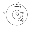
- the single figure shows a device unit with a light source and a light-sensitive receiver and two diaphragms.
- the outer part of a device unit is fixed and carries a light source 3, the modulated luminous flux of which contains the information to be transmitted.
- the inner part of the device unit identified by 20, rotates about an axis 21 and contains a light-sensitive receiving device 4 which converts the received modulated luminous flux of the light source 3 into electrical signals.
- the direction of radiation flow can also be reversed so that the outer part contains the receiving device and the inner part contains the light source. It is also conceivable that the outer part rotates and the inner part is fixed.
- the dynamics of the light-sensitive receiving device is in Embodiment of the invention so large that the electrical signals generated by them are a clear measure of the information transmitted, regardless of the distance of the receiving devices from the light source.
- the light source, receiver unit and aperture are provided with a surface that is as completely but diffusely reflective as possible.
Landscapes
- Physics & Mathematics (AREA)
- Electromagnetism (AREA)
- Engineering & Computer Science (AREA)
- Computer Networks & Wireless Communication (AREA)
- Signal Processing (AREA)
- General Physics & Mathematics (AREA)
- Optical Communication System (AREA)
- Arrangements For Transmission Of Measured Signals (AREA)
Description
- Die Erfindung betrifft eine Vorrichtung zur Übertragung von Informationen zwischen einem rotierenden und einem feststehenden Geräteteil, wobei eines der Geräteteile mindestens eine Lichtquelle für einen die Information enthaltenden modulierten Lichtstrom trägt und das andere Geräteteil mindestens eine lichtempfindliche Empfangseinrichtung trägt und wobei kein direktes Licht der Lichtquelle und kein nur einmal reflektiertes Licht der Lichtquelle die Empfangseinrichtung trifft.
- Bei derartigen Vorrichtungen wird eine möglichst große Verschleißfreiheit angestrebt. Außerdem soll durch eine derartige Vorrichtung einem vorhandenen Stromkreis kein zusätzliches Rauschen aufgeprägt werden.
- Es ist bekannt, zur Übertragung von Signalen und/oder Energien zwischen zwei relativ zueinander rotierenden Geräteteilen mechanische Schleifringe zu verwenden. Man versteht darunter einen metallischen Ring, der über einen Federkontakt mit einem elektrischen Gerät verbunden ist und bei Drehung oder Verschiebung schleifend einen elektrischen Kontakt herstellt. So kann beispielsweise mit dem Läufer eines elektrischen Generators ein metallischer Ring verbunden sein, auf dem zur Stromzufuhr oder -abnahme die sog. Bürste aufliegt. Derartige Schleifringe sind mit hohem Verschleiß behaftet, führen zu Reibungsverlusten und verursachen unerwünschte Stromwärme. Bei gealterten Schleifringen kann es auch zu kurzzeitigen Unterbrechungen in der Kontaktgabe kommen. Aus der US-PS 4190 318 ist eine Vorrichtung bekannt, die zur Informationsübermittlung zwischen zwei relativ zueinander rotierenden Geräteteilen einen modulierten Lichtstrom und einen lichtempfindlichen Detektor verwendet und die durch die Verwendung mehrerer, in regelmäßigem Abstand auf dem Umfang eines der Geräteteile angeordnete Sende- bzw. Empfangseinrichtungen gekennzeichnet ist. Ein Nachteil dieser bekannten Vorrichtungen besteht darin, daß bei konstantem Sendesignal das von der Empfangseinrichtung empfangene Signal bei Rotation der beiden Geräteteile gegeneinander eine Modulation erfährt. Dem zu übertragenden Nutzsignal wird somit ein rotationsbedingtes Störsignal überlagert. Eine Übertragung analog verschlüsselter Information ist bei dieser bekannten Vorrichtung dadurch verhindert. Auch bei geeigneter digitaler Verschlüsselung der zu übertragenden Information ist infolge der durch die Rotation bedingten Amplitudenmodulation der Signale ein erheblicher Dynamikbereich der elektronischen Schaltungsteile erforderlich. Aus. der US-A4175230 ist eine Informationsübermittlungsvorrichtung bekannt, bei der die Flächen der Geräteteile zwischen Lichtquelle und Empfänger verspiegelt sind. Die verspiegelten Flächen sind stoßempfindlich.
- Der Erfindung liegt die Aufgabe zugrunde, eine Vorrichtung zum Übertragen von Information und/oder Energien zwischen zwei relativ zueinander rotierenden Geräteteilen anzugeben, die frei ist vom Nachteil der bekannten Vorrichtung. Außerdem soll die Information in einer elektronisch leicht zu verarbeitenden Form zu übertragen werden.
- Diese Aufgabe wird erfindungsgemäß dadurch gelöst, daß das die Lichtquelle tragende Geräteteil und das die Empfangseinrichtung tragende Geräteteil möglichst vollständig, jedoch diffus reflektierende Oberflächen besitzen und daß zwischen Lichtquelle und Empfangseinrichtung mindestens eine Blende vorgesehen ist, die ebenfalls eine möglichst vollständig, jedoch diffus reflektierende Oberfläche besitzt.
- Der Wellenlängenbereich des für die Vorrichtung verwendeten Lichtes kann vom ultravioletten bis zum infraroten Bereich gehen.
- Durch die Oberflächengestaltung der Blenden wird erreicht, daß der bei konstantem Sendesignal von der Empfangseinrichtung empfangene Strahlungsfluß auch bei Rotation der Geräteteile gegeneinander unabhängig von der relativen Stellung der Teile zueinander praktisch konstant ist.
- Für die elektronische Verarbeitung der Informationen können diese digital codiert oder analog übertragen werden.
- Die mit der Erfindung erzielten Vorteile liegen insbesondere in der Freiheit des Nutzsignals von rotationsbedingten Störsignalen, in der leichten Verarbeitbarkeit der übertragenen Informationen und in der Möglichkeit, gleichzeitig mehrere Informationsflüsse zu übertragen.
- Zur Übertragung mehrerer Informationsflüsse können entweder mehrere, optisch getrennte Kanäle vorgesehen sein oder es kann jedem Informationsfluß ein eigener Wellenlängenbereich zugeordnet werden.
- Ein Ausführungsbeispiel der Erfindung ist in der Zeichnung dargestellt und wird im folgenden näher beschrieben.
- Die einzige Figur zeigt eine Geräteeinheit mit einer Lichtquelle und einem lichtempfindlichen Empfänger und zwei Blenden.
- Im gezeigten Ausführungsbeispiel ist der äußere, mit dem Bezugszeichen 10 gekennzeichnete Teil einer Geräteeinheit feststehend und trägt eine Lichtquellen 3, deren modulierter Lichtstrom die zu übertragende Information enthält. Der innere, mit 20 gekennzeichnete Teil der Geräteeinheit rotiert um eine Achse 21 und enthält eine lichtempfindliche Empfangseinrichtungen 4, die den empfangenen modulierten Lichtstrom der Lichtquelle 3 in elektrische Signale umsetzen. Die Strahlungsflußrichtung kann auch umgekehrt sein, so daß der äußere Teil die Empfangseinrichtung enthält und der innere Teil die Lichtquelle. Ebenso ist es denkbar, daß der äußere Teil rotiert und der innere Teil feststeht. Die Dynamik der lichtempfindlichen Empfangseinrichtung ist im Ausführungsbeispiel der Erfindung so groß, daß die von ihnen erzeugten elektrischen Signale unabhängig von der Entfernung der Empfangseinrichtungen von der Lichtquelle ein eindeutiges Maß für die übermittelten Informationen sind. Die Blenden 5,5' sorgen dafür, daß nicht das direkte emittierte Licht der Lichtquelle 3 die Empfangseinheit 4 trifft. Lichtquelle, Empfangseinheit und Blende sind mit einer möglichst vollständig jedoch diffus reflektierenden Oberfläche versehen.
Claims (6)
Applications Claiming Priority (2)
| Application Number | Priority Date | Filing Date | Title |
|---|---|---|---|
| DE3222441 | 1982-06-15 | ||
| DE19823222441 DE3222441A1 (de) | 1982-06-15 | 1982-06-15 | Vorrichtung zur uebertragung von informationen |
Publications (2)
| Publication Number | Publication Date |
|---|---|
| EP0098403A1 EP0098403A1 (de) | 1984-01-18 |
| EP0098403B1 true EP0098403B1 (de) | 1986-10-01 |
Family
ID=6166097
Family Applications (1)
| Application Number | Title | Priority Date | Filing Date |
|---|---|---|---|
| EP83105678A Expired EP0098403B1 (de) | 1982-06-15 | 1983-06-10 | Vorrichtung zur Übertragung von Informationen |
Country Status (3)
| Country | Link |
|---|---|
| US (1) | US4588895A (de) |
| EP (1) | EP0098403B1 (de) |
| DE (2) | DE3222441A1 (de) |
Families Citing this family (8)
| Publication number | Priority date | Publication date | Assignee | Title |
|---|---|---|---|---|
| JPH01145250A (ja) * | 1987-08-28 | 1989-06-07 | Toyoda Gosei Co Ltd | ステアリングホイール |
| US4910408A (en) * | 1988-09-30 | 1990-03-20 | Bently Nevada Corp. | Fiberglass collar for data transfer from rotatable shaft |
| DE9014037U1 (de) * | 1990-10-09 | 1990-12-20 | Emuge-Werk Richard Glimpel Fabrik für Präzisionswerkzeuge, 8560 Lauf | Gewindeschneid- oder Bohrfutter |
| IL98421A (en) * | 1991-06-09 | 1995-07-31 | Elscint Ltd | Optical communication link |
| DE4325323C1 (de) * | 1993-07-28 | 1994-08-25 | Siemens Ag | Berührungsloses optisches Datenübertragungssystem |
| JPH10276131A (ja) * | 1997-03-28 | 1998-10-13 | Victor Co Of Japan Ltd | 光送受信装置 |
| DE10240357B4 (de) * | 2002-09-02 | 2016-10-06 | Wabco Gmbh | Luftfederungsanlage für ein Fahrzeug |
| EP2083199B1 (de) | 2008-01-22 | 2018-11-07 | Eaton Intelligent Power Limited | Getriebeschaltsystem |
Family Cites Families (7)
| Publication number | Priority date | Publication date | Assignee | Title |
|---|---|---|---|---|
| DE2441359A1 (de) * | 1974-08-29 | 1976-03-11 | Licentia Gmbh | Anordnung zur kontaktlosen signaluebertragung zwischen relativ zueinander bewegten teilen |
| GB1538485A (en) * | 1976-01-07 | 1979-01-17 | Rank Organisation Ltd | Opto-electric device |
| US4027945A (en) * | 1976-03-04 | 1977-06-07 | The United States Of America As Represented By The Secretary Of The Navy | Optical sliprings |
| GB1575672A (en) * | 1977-05-05 | 1980-09-24 | Standard Telephones Cables Ltd | Information transfer |
| US4190318A (en) * | 1978-01-19 | 1980-02-26 | Honeywell Inc. | Optical slip ring apparatus utilizing radial light signals |
| GB2074313B (en) * | 1980-03-25 | 1984-08-30 | Nissan Motor | Optical signal transmission systems |
| US4466695A (en) * | 1981-11-09 | 1984-08-21 | International Telephone & Telegraph Corporation | Rotary annular signal data coupler |
-
1982
- 1982-06-15 DE DE19823222441 patent/DE3222441A1/de not_active Withdrawn
-
1983
- 1983-06-10 DE DE8383105678T patent/DE3366565D1/de not_active Expired
- 1983-06-10 US US06/503,312 patent/US4588895A/en not_active Expired - Fee Related
- 1983-06-10 EP EP83105678A patent/EP0098403B1/de not_active Expired
Also Published As
| Publication number | Publication date |
|---|---|
| US4588895A (en) | 1986-05-13 |
| EP0098403A1 (de) | 1984-01-18 |
| DE3222441A1 (de) | 1983-12-15 |
| DE3366565D1 (en) | 1986-11-06 |
Similar Documents
| Publication | Publication Date | Title |
|---|---|---|
| DE4020939C2 (de) | Optische Nachrichtenverbindung | |
| DE2855379C2 (de) | ||
| DE2819125A1 (de) | Einrichtung zur uebertragung von informationen zwischen zwei zueinander beweglichen teilen | |
| DE2924847C2 (de) | ||
| DE4218692B4 (de) | Einrichtung zum Übertragen von Daten zwischen einem rotierenden und einem stationären Teil | |
| EP0098403A1 (de) | Vorrichtung zur Übertragung von Informationen | |
| DE2700407A1 (de) | Einrichtung zum uebertragen von information zwischen zwei in bezug aufeinander verdrehbaren bauteilen | |
| GB1545416A (en) | Torque transmitting assemblies | |
| CH643975A5 (de) | Optische abtastvorrichtung und verfahren zu deren betrieb. | |
| EP1638206A2 (de) | Positionsüberwachungseinrichtung | |
| ES2042109T3 (es) | Dispositivo de union para elementos de andamio. | |
| ES507300A0 (es) | Un procedimiento para la formacion de un recubrimiento polimerico de polisocianato poliester copolimero de adicion sobreun sustrato solido. | |
| DE69218361T2 (de) | Auf einem Kraftfahrzeug angeordnete Einrichtung zur Entdeckung und Identifizierung von Hindernissen | |
| AT4976U1 (de) | Markenscheibe für einen drehwinkelaufnehmer, winkelaufnehmer für rotierende bauteile sowie verfahren zur ermittlung eines referenzwertes | |
| DE69816209T2 (de) | Störung reduzierenden zur bilderzeugender Daten | |
| DE2751064C2 (de) | Identifizierungsvorrichtung | |
| DE3922440A1 (de) | Rotationswinkeldetektor | |
| EP0560315B1 (de) | Einrichtung zur leitungsungebundenen Signalübertragung mittels Licht | |
| DE202014100149U1 (de) | Vorrichtung zur Überwachung einer Applikationsstruktur auf einem Werkstück | |
| DE3907033A1 (de) | Vorrichtung zur messung und uebertragung von druck- und temperaturwerten im ex- gefaehrdeten/nicht ex- gefaehrdeten bereich | |
| EP0007290B1 (de) | Zielscheibeneinrichtung | |
| EP0807341B1 (de) | Vorrichtung zur informationsübertragung mit optischen signalen zwischen einer sendeeinheit und einer hierzu beweglichen empfangseinheit | |
| DE3624874A1 (de) | Winkelgeber | |
| DE77570T1 (de) | Bandzufuehrapparat fuer gemusterte baender. | |
| EP3769445A1 (de) | System und verfahren zum betreiben eines systems mit zumindest einem ersten und einem zweiten mobilteil |
Legal Events
| Date | Code | Title | Description |
|---|---|---|---|
| PUAI | Public reference made under article 153(3) epc to a published international application that has entered the european phase |
Free format text: ORIGINAL CODE: 0009012 |
|
| AK | Designated contracting states |
Designated state(s): CH DE FR GB LI NL |
|
| 17P | Request for examination filed |
Effective date: 19840706 |
|
| GRAA | (expected) grant |
Free format text: ORIGINAL CODE: 0009210 |
|
| AK | Designated contracting states |
Kind code of ref document: B1 Designated state(s): CH DE FR GB LI NL |
|
| REF | Corresponds to: |
Ref document number: 3366565 Country of ref document: DE Date of ref document: 19861106 |
|
| ET | Fr: translation filed | ||
| PLBE | No opposition filed within time limit |
Free format text: ORIGINAL CODE: 0009261 |
|
| STAA | Information on the status of an ep patent application or granted ep patent |
Free format text: STATUS: NO OPPOSITION FILED WITHIN TIME LIMIT |
|
| 26N | No opposition filed | ||
| PGFP | Annual fee paid to national office [announced via postgrant information from national office to epo] |
Ref country code: GB Payment date: 19910614 Year of fee payment: 9 Ref country code: CH Payment date: 19910614 Year of fee payment: 9 |
|
| PGFP | Annual fee paid to national office [announced via postgrant information from national office to epo] |
Ref country code: FR Payment date: 19910628 Year of fee payment: 9 |
|
| PGFP | Annual fee paid to national office [announced via postgrant information from national office to epo] |
Ref country code: NL Payment date: 19910630 Year of fee payment: 9 |
|
| PG25 | Lapsed in a contracting state [announced via postgrant information from national office to epo] |
Ref country code: GB Effective date: 19920610 |
|
| PG25 | Lapsed in a contracting state [announced via postgrant information from national office to epo] |
Ref country code: LI Effective date: 19920630 Ref country code: CH Effective date: 19920630 |
|
| PG25 | Lapsed in a contracting state [announced via postgrant information from national office to epo] |
Ref country code: NL Effective date: 19930101 |
|
| GBPC | Gb: european patent ceased through non-payment of renewal fee |
Effective date: 19920610 |
|
| NLV4 | Nl: lapsed or anulled due to non-payment of the annual fee | ||
| PG25 | Lapsed in a contracting state [announced via postgrant information from national office to epo] |
Ref country code: FR Effective date: 19930226 |
|
| REG | Reference to a national code |
Ref country code: CH Ref legal event code: PL |
|
| REG | Reference to a national code |
Ref country code: FR Ref legal event code: ST |
|
| PGFP | Annual fee paid to national office [announced via postgrant information from national office to epo] |
Ref country code: DE Payment date: 19950223 Year of fee payment: 12 |
|
| PG25 | Lapsed in a contracting state [announced via postgrant information from national office to epo] |
Ref country code: DE Effective date: 19960301 |