EP0097798A2 - Abtastsystem mit Faseroptik - Google Patents
Abtastsystem mit Faseroptik Download PDFInfo
- Publication number
- EP0097798A2 EP0097798A2 EP83104578A EP83104578A EP0097798A2 EP 0097798 A2 EP0097798 A2 EP 0097798A2 EP 83104578 A EP83104578 A EP 83104578A EP 83104578 A EP83104578 A EP 83104578A EP 0097798 A2 EP0097798 A2 EP 0097798A2
- Authority
- EP
- European Patent Office
- Prior art keywords
- scanner
- fiber optic
- housing
- fiber
- pulses
- Prior art date
- Legal status (The legal status is an assumption and is not a legal conclusion. Google has not performed a legal analysis and makes no representation as to the accuracy of the status listed.)
- Granted
Links
Images
Classifications
-
- G—PHYSICS
- G06—COMPUTING OR CALCULATING; COUNTING
- G06K—GRAPHICAL DATA READING; PRESENTATION OF DATA; RECORD CARRIERS; HANDLING RECORD CARRIERS
- G06K7/00—Methods or arrangements for sensing record carriers, e.g. for reading patterns
- G06K7/10—Methods or arrangements for sensing record carriers, e.g. for reading patterns by electromagnetic radiation, e.g. optical sensing; by corpuscular radiation
- G06K7/10544—Methods or arrangements for sensing record carriers, e.g. for reading patterns by electromagnetic radiation, e.g. optical sensing; by corpuscular radiation by scanning of the records by radiation in the optical part of the electromagnetic spectrum
- G06K7/10821—Methods or arrangements for sensing record carriers, e.g. for reading patterns by electromagnetic radiation, e.g. optical sensing; by corpuscular radiation by scanning of the records by radiation in the optical part of the electromagnetic spectrum further details of bar or optical code scanning devices
- G06K7/10881—Methods or arrangements for sensing record carriers, e.g. for reading patterns by electromagnetic radiation, e.g. optical sensing; by corpuscular radiation by scanning of the records by radiation in the optical part of the electromagnetic spectrum further details of bar or optical code scanning devices constructional details of hand-held scanners
-
- G—PHYSICS
- G06—COMPUTING OR CALCULATING; COUNTING
- G06K—GRAPHICAL DATA READING; PRESENTATION OF DATA; RECORD CARRIERS; HANDLING RECORD CARRIERS
- G06K2207/00—Other aspects
- G06K2207/1018—Source control
Definitions
- This invention relates to a scanner and, more particularly, to a probe scanner for detecting coded elements.
- Wands for reading bar codes are presently expensive and require rugged construction to withstand the usual normal handling. They typically contain light emitting diodes, photo detectors, optical components and electronic circuits which result in complexity and high cost. Inherent repeated use requires that the wand be replaced or repaired often. Accordingly, a low cost, rugged, throw-away wand would minimize maintenance and reduce the overall operating expense.
- each of these patents requires the use of a first fiber, or bundle of fibers, for transmitting light from the light source of the reading end of the probe and a second fiber, or bundle of fibers, for returning the reflected light from the end of the probe to the light detector. None of them disclose the use of a single fiber for carrying the light in both directions.
- the one exception above is the McMurtry patent assigned to the present applicant, International Business Machines Corporation.
- the arrangement in the McMurtry patent 3,711,723 uses a single bundle of fibers for both the transmitted and reflected light. It does not use a single fiber and the pulse generation and detection of the present invention. It uses a continuous light source as do all of the above listed patents.
- the McMurtry patent keeps the reflected light separated from the transmitted light by means of a rather complex optical mirror and aperture arrangement.
- the main advantage of the present invention is the use of a single fiber within the hand-held wand for transmission of light pulses in both directions, that is, for illuminating the bar code and for reading the reflected pulses therefrom.
- Using the single fiber and the pulse type coding provides an inexpensive probe as well as higher resolution for detecting the light reflecting transitions, that is, the edges of the reflective bar codes.
- the present invention relates to a fiber optic scanner system for reading coded patterns when the hand-held probe is moved across the coded pattern.
- the handheld scanner or probe consists of a housing having a scanner tip attached at the reading end thereof. At the other end of the probe housing is located the connector end.
- a single optical fiber is located in the housing and extends into the scanner tip into the reading position. The other end of the fiber emerges from the connector end of the housing.
- a remote terminal is associated with the scanner and has a single optical fiber link connected between the scanner probe and the remote terminal.
- An optical signal generator is located in the remote terminal for producing and transmitting optical pulses of a given width and at a predetermined frequency.
- optical pulses are sent over the fiber link and through the fiber in the scanner housing to the scanner tip from whence they are beamed onto the bar code.
- a receiver is located in the remote terminal, receiving light pulses reflected from the coded pattern into the reading end of the single optical fiber transmission line located in the scanner tip.
- a light coupler is also located in the remote terminal for coupling reflected light pulses from the single fiber into the receiver.
- the optical signal generator pulse width and frequency and the bar code width and spacing are selected to produce the reflected light pulses between the generated light pulses, thereby minimizing interference therebetween.
- the use of the single fiber in the hand-held probe, along with the pulse type illumination, provides a system of high resolution of detection of the bar code and, in addition, provides an inexpensive probe which can be discarded when worn out or defective.
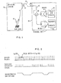
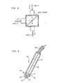
- an optical probe is shown generally at 10 in position to scan a bar type code.
- the probe 10 shown in detail in Fig.3, has a relatively long barrel or housing 12 made of plastic or some other light suitable material such as aluminium.
- the housing 12 has an internally threaded section 14 at the scanning end 16 of the housing.
- a conically shaped tip member 18 made of a hard metal or sapphire has external threads 20 on the wide end thereof adapted to screw into the internally threaded portion 14 of the housing 12 to make flush engagement therewith.
- the conically shaped tip member 18 has a central opening 22 which extends through the apex 24 of the cone.
- a single fiber 26 made of glass or plastic extends through the housing 12 and through the opening 22 running through the center of the tip member 18.
- the fiber 26 terminates at the opening 22 at the apex 24 of the cone shaped tip member 18.
- the jacket 28 of the portion of the fiber 26 which extends into the housing 12 is removed before it is placed in the housing and the tip member.
- the jacketed portion of the fiber 26 is attached to the upper end of the housing 12 by gluing or other attachment means.
- the probe-type scanner 10 is usually utilized at an operating station 30.
- a connector 32 is usually provided somewhere near the station 30 to detachably connect an optical fiber link 34 from the operating station 30 to the terminal unit 36.
- a connector 38 is made available at the terminal unit 36 for detachably connecting the other end of the fiber link thereto.
- the reason for the connectors 32 and 38 is strictly for convenience in replacing a worn or damaged probe or to provide a new transmission link 34 between the operating station 30 and the terminal unit 36.
- the fiber optic communication link 34 can be of various lengths depending on the desired location of the terminal unit 36 with respect to the operating station 30 where the probe scanner 10 is to do the reading of the coded information. The ideal length would be sufficient to introduce enough delay such that the reflected pulses would be in between the transmitted pulses. However, this is not critical since the terminal unit 36 can include a fiber coil 40 in the optical line which introduces the desired delay.
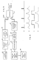
- the terminal unit 36 includes all of the optics, drivers, receivers and pulse generators for sustaining the coded information scanning and reading. None of these.are located in the probe scanner 10.
- the terminal unit 36 includes pulse generating circuits 42 and a driver circuit 44 for generating optical pulses of a predetermined width at the required frequency and transmitting them over the optical link 34 through the wand or probe 10 so that they are beamed onto the bar code and correspondingly reflected. It should be appreciated, that the reflections will depend on the material upon which the bars are placed, in other words, the spaces between the code bars.
- reflected pulses are picked up by the single optic fiber 26 in the scanner tip 18 and transmitted via the single fiber to the terminal unit 36 where they are received by a suitable receiver 46 and the bar code essentially decoded in the recovery circuits 48.
- the transmitted and received optical pulses in the terminal unit 36 are separated by the correct selection of the transmitted pulse width and frequency and the bar code width and spacing.
- a clock generator 50 produces a 10 MHz square wave that feeds a divide-by-ten counter/ timer 52.
- the counter/timer provides two outputs. One output is connected to the laser driver and laser 54 and the other to analog switch 60.
- the laser driver 54 light output pulses are connected through a single fiber to a coupler 56 which passes the light pulses to the single fiber link which carries the pulses to the probe scanner where they are beamed onto the bar code.
- the light pulses reflected from the bar code enter the end of the single fiber in the probe, pass through the single fiber link 34 and are passed through coupler 56 to the detector/preamplifier 58.
- the detector/preamplifier 58 converts the received light pulses to electrical signals that feed the analog switch 60.
- the analog switch is operated only during the period when return pulses occur, see waveform C of Fig.6. High intensity laser output pulses are only partially coupled (or reflected) by the coupler 56 even though typical coupler devices have some directional properties. Since the analog switch 60 is only actuated during the time that the appropriate signals are present, adverse laser output signals do not enter integrator 62. A timing gate or window is provided by the counter/timer 52. The output of the integrator 62 feeds an analog to digital converter 64 which produces digital representations of the pulse amplitude. These amplitudes are stored in the digital processor 66.
- the processor tracks the varying amplitude of the return pulses, averages signals, detects positive and negative peaks, and determines a threshold halfway between the peak values.
- the digital processor decodes the meaning of the bar code for further information transfer.
- waveform A shows a schematic representation of the laser light output from the laser driver and laser 54. These are the light pulses that are sent over the optical fiber link 34 to the probe 10 for reflection from the coded information bars.
- the reflected pulses after being detected and amplified are shown as pulse waveform B representing the input to the analog switch 60.
- the analog control switch 60 is opened for a preset window time as shown in waveform C of Figure 6. This window is determined, as previously mentioned, by the output from counter/timer 52.
- the pulse existing during the window time is sent to the integrator 62 and subsequently converted to a digital representation and sent to the digital processor 46 for decoding and further operations.
- the wavelength of transmission of light pulses is selected to provide sensing of many colors of bar codes. It is nominally 1 MH z ( 1 0 -9 meters).
- a typical probe should operate at speeds from 2 to 20 inches per second and detect bars and spaces as narrow as 0.01 inches (10 mils.). At the 1 MHz pulse per second rate and 2 inches per second wand speed, 5,000 pulses will be reflected by this minimum width bar or space (500,000 pulses per inch X 0.01 inches). At 20 inches per second probe speed, 500 pulses will be reflected. Both cases represent adequate pulses for reliable processing.
- a schematic representation of the driver pulses and received reflected pulses are shown in Figure 2 as well as the reconstructed bar pattern from the driver pulses and received reflected signals. It should be noted that there is a separation between the pulses of one microsecond and the pulse width itself is equal to 0.1 microsecond.
- the coupler 56 shown in Figs. 1 and 5 is shown in further detail in Figure 4.
- the coupler is known as a threeport coupler which uses a half mirror and generally uses lenses to couple in and out of the half mirror element.
- This type of coupler has directional properties. The arrangement is such that the light signals are sent to the coupler 56 from the laser driver and laser 54 through port A which via the half mirror unit sends the pulse information out on port C to the probe.
- the reflected pulse information is received at port C of the coupelr 56, it is sent out on port B to the detector/ preamplifier 58.
- the pulse repetition rate to be 1 MHz and the pulse width to be 100 ns. If the reflected pulses are to arrive about 500 ns after a transmitted pulse is generated, the total fiber length would be about 166 feet. (Light travels at about 1.5 ns per foot) The length of coil 40 would insure the proper delay, but obviously this need not to be critical. If the wand is passed over a bar code in 0.1 seconds, 100,000 pulses will strike the surface and provide adequate resolution for reconstruction.
- a low cost wand or probe is possible with all of the optics and electronics packaged in the terminal unit and with a single optic fiber providing two way multiplexed transmission in the probe such that the probe is replacable with the minimum of cost.
Landscapes
- Physics & Mathematics (AREA)
- Engineering & Computer Science (AREA)
- Electromagnetism (AREA)
- Artificial Intelligence (AREA)
- Toxicology (AREA)
- General Health & Medical Sciences (AREA)
- Health & Medical Sciences (AREA)
- Computer Vision & Pattern Recognition (AREA)
- General Physics & Mathematics (AREA)
- Theoretical Computer Science (AREA)
- Optical Radar Systems And Details Thereof (AREA)
- Length Measuring Devices By Optical Means (AREA)
- Arrangements For Transmission Of Measured Signals (AREA)
Applications Claiming Priority (2)
| Application Number | Priority Date | Filing Date | Title |
|---|---|---|---|
| US393258 | 1982-06-29 | ||
| US06/393,258 US4467196A (en) | 1982-06-29 | 1982-06-29 | Single fiber optic wand system |
Publications (3)
| Publication Number | Publication Date |
|---|---|
| EP0097798A2 true EP0097798A2 (de) | 1984-01-11 |
| EP0097798A3 EP0097798A3 (en) | 1987-01-28 |
| EP0097798B1 EP0097798B1 (de) | 1989-04-19 |
Family
ID=23553959
Family Applications (1)
| Application Number | Title | Priority Date | Filing Date |
|---|---|---|---|
| EP83104578A Expired EP0097798B1 (de) | 1982-06-29 | 1983-05-10 | Abtastsystem mit Faseroptik |
Country Status (4)
| Country | Link |
|---|---|
| US (1) | US4467196A (de) |
| EP (1) | EP0097798B1 (de) |
| JP (1) | JPS5914075A (de) |
| DE (1) | DE3379692D1 (de) |
Families Citing this family (19)
| Publication number | Priority date | Publication date | Assignee | Title |
|---|---|---|---|---|
| JPS5949677A (ja) * | 1982-09-14 | 1984-03-22 | Sogo Keibi Hoshiyou Kk | 光カ−ド装置 |
| NL8303168A (nl) * | 1983-09-14 | 1985-04-01 | Philips Nv | Inrichting voor het uitlezen van balken gecodeerde informatie. |
| USD288337S (en) | 1984-03-29 | 1987-02-17 | Price/Stern/Sloan/Publishers, Inc. | Electronic detection unit for an educational instrument |
| US5059778A (en) * | 1986-09-29 | 1991-10-22 | Mars Incorporated | Portable data scanner apparatus |
| US4845349A (en) * | 1986-09-30 | 1989-07-04 | Spectra-Physics, Inc. | Bar code scanner laser emission reduction |
| US5514861A (en) * | 1988-05-11 | 1996-05-07 | Symbol Technologies, Inc. | Computer and/or scanner system mounted on a glove |
| US5616908A (en) * | 1991-09-17 | 1997-04-01 | Metrologic Instruments, Inc. | Automatic countertop laser scanner with flickering laser scanner beam for improved visibility thereof during bar code symbol reading |
| US5266803A (en) * | 1991-03-03 | 1993-11-30 | Bio-Rad Labratories, Inc. | Fiber optic storage phosphor imaging plate scanner |
| US5610387A (en) * | 1992-05-15 | 1997-03-11 | Symbol Technologies, Inc. | Portable optical scanning system worn by a user for reading indicia of differing light reflectivity |
| US6811088B2 (en) * | 1993-05-28 | 2004-11-02 | Symbol Technologies, Inc. | Portable data collection system |
| US6853293B2 (en) | 1993-05-28 | 2005-02-08 | Symbol Technologies, Inc. | Wearable communication system |
| US7387253B1 (en) | 1996-09-03 | 2008-06-17 | Hand Held Products, Inc. | Optical reader system comprising local host processor and optical reader |
| US5652412A (en) * | 1994-07-11 | 1997-07-29 | Sia Technology Corp. | Pen and paper information recording system |
| US5661506A (en) * | 1994-11-10 | 1997-08-26 | Sia Technology Corporation | Pen and paper information recording system using an imaging pen |
| US5861616A (en) * | 1996-10-01 | 1999-01-19 | Mustek Systems, Inc. | Method and device for recognizing a waveform of an analog signal |
| US6075240A (en) * | 1998-07-30 | 2000-06-13 | Nec Usa, Inc. | Hand-held plastic optical fiber linear scanner for reading color images formed on a surface |
| US6157027A (en) * | 1998-12-01 | 2000-12-05 | Nec Usa, Inc. | Modular optical fiber color image scanner with all-optical scanner head having side-coupled light guide for providing illumination light to the scanner head |
| USD460068S1 (en) | 2000-03-27 | 2002-07-09 | Symbol Technologies, Inc. | Portable handheld terminal housing |
| US7464877B2 (en) * | 2003-11-13 | 2008-12-16 | Metrologic Instruments, Inc. | Digital imaging-based bar code symbol reading system employing image cropping pattern generator and automatic cropped image processor |
Family Cites Families (5)
| Publication number | Priority date | Publication date | Assignee | Title |
|---|---|---|---|---|
| SE380647B (sv) * | 1970-12-17 | 1975-11-10 | Svenska Dataregister Ab | Indikatoranordning for en optisk dataavkenningsanordning. |
| GB1357173A (en) * | 1971-10-23 | 1974-06-19 | Marconi Co Ltd | Coded record reading systems |
| US3983389A (en) * | 1975-04-11 | 1976-09-28 | International Business Machines Corporation | Wand for reading optically encoded graphic symbols |
| US4154529A (en) * | 1977-03-21 | 1979-05-15 | Andrew Corporation | System for detecting reflected laser beams |
| JPS55124049U (de) * | 1979-02-20 | 1980-09-03 |
-
1982
- 1982-06-29 US US06/393,258 patent/US4467196A/en not_active Expired - Fee Related
-
1983
- 1983-05-10 EP EP83104578A patent/EP0097798B1/de not_active Expired
- 1983-05-10 DE DE8383104578T patent/DE3379692D1/de not_active Expired
- 1983-06-10 JP JP58102961A patent/JPS5914075A/ja active Granted
Also Published As
| Publication number | Publication date |
|---|---|
| EP0097798A3 (en) | 1987-01-28 |
| JPS6229836B2 (de) | 1987-06-29 |
| DE3379692D1 (en) | 1989-05-24 |
| EP0097798B1 (de) | 1989-04-19 |
| JPS5914075A (ja) | 1984-01-24 |
| US4467196A (en) | 1984-08-21 |
Similar Documents
| Publication | Publication Date | Title |
|---|---|---|
| US4467196A (en) | Single fiber optic wand system | |
| US4286145A (en) | Fiber optic bar code reader | |
| EP0404874A4 (en) | Optical data link system, and methods of constructing and utilizing same | |
| EP0240157A2 (de) | Bidirektionales optisches Übertragungssystem mit einzelner Übertragungsleitung | |
| EP0045585B1 (de) | Optische Drehkupplung | |
| US4857727A (en) | Optically powered remote sensors with timing discrimination | |
| DE59705179D1 (de) | Entfernungsmesser | |
| US5539560A (en) | Optical router with optical control | |
| US5629511A (en) | Bar code scanner and scanning system for various types of operations | |
| US5408080A (en) | Electronically triggered bar code scanner | |
| HUT48782A (en) | Reflective transmitter and receiver apparatus for double-direction light-conductor telecommunication system | |
| JPS6449019A (en) | Optical switch array | |
| JPS6471247A (en) | Interface circuit | |
| US20020105657A1 (en) | High speed laser micrometer | |
| US6860026B2 (en) | Machine tool probe | |
| EP0395828B1 (de) | Optischer Übertragungsapparat | |
| US5311002A (en) | Circuit for dealing with a bar code signal and a high speed electric signal | |
| US5270541A (en) | Multiple photoelectric switch apparatus | |
| JPH04263399A (ja) | 非電気的な信号及びエネルギーの伝送による測定装置 | |
| CN114124208A (zh) | 一种消除物理点噪声干扰的光纤编码识别系统及方法 | |
| KR940007732A (ko) | 잠금 케이블 커넥터 어셈블리가 설치된 바 코드 심볼 판독기 | |
| GB2131248A (en) | Test equipment for testing an optical fibre transmission line | |
| JPH078631A (ja) | 同時プレイ機能を持ったゲーム装置 | |
| JPH0650841A (ja) | 光ファイバ線路破断検出方法およびその装置 | |
| JPH0380380A (ja) | バーコード読み取り装置 |
Legal Events
| Date | Code | Title | Description |
|---|---|---|---|
| PUAI | Public reference made under article 153(3) epc to a published international application that has entered the european phase |
Free format text: ORIGINAL CODE: 0009012 |
|
| AK | Designated contracting states |
Designated state(s): DE FR GB |
|
| 17P | Request for examination filed |
Effective date: 19840426 |
|
| PUAL | Search report despatched |
Free format text: ORIGINAL CODE: 0009013 |
|
| AK | Designated contracting states |
Kind code of ref document: A3 Designated state(s): DE FR GB |
|
| 17Q | First examination report despatched |
Effective date: 19880118 |
|
| GRAA | (expected) grant |
Free format text: ORIGINAL CODE: 0009210 |
|
| AK | Designated contracting states |
Kind code of ref document: B1 Designated state(s): DE FR GB |
|
| REF | Corresponds to: |
Ref document number: 3379692 Country of ref document: DE Date of ref document: 19890524 |
|
| ET | Fr: translation filed | ||
| PLBE | No opposition filed within time limit |
Free format text: ORIGINAL CODE: 0009261 |
|
| STAA | Information on the status of an ep patent application or granted ep patent |
Free format text: STATUS: NO OPPOSITION FILED WITHIN TIME LIMIT |
|
| 26N | No opposition filed | ||
| PGFP | Annual fee paid to national office [announced via postgrant information from national office to epo] |
Ref country code: GB Payment date: 19920408 Year of fee payment: 10 |
|
| PGFP | Annual fee paid to national office [announced via postgrant information from national office to epo] |
Ref country code: FR Payment date: 19920427 Year of fee payment: 10 |
|
| PGFP | Annual fee paid to national office [announced via postgrant information from national office to epo] |
Ref country code: DE Payment date: 19920523 Year of fee payment: 10 |
|
| PG25 | Lapsed in a contracting state [announced via postgrant information from national office to epo] |
Ref country code: GB Effective date: 19930510 |
|
| GBPC | Gb: european patent ceased through non-payment of renewal fee |
Effective date: 19930510 |
|
| PG25 | Lapsed in a contracting state [announced via postgrant information from national office to epo] |
Ref country code: FR Effective date: 19940131 |
|
| PG25 | Lapsed in a contracting state [announced via postgrant information from national office to epo] |
Ref country code: DE Effective date: 19940201 |
|
| REG | Reference to a national code |
Ref country code: FR Ref legal event code: ST |