EP0097752B1 - Tastspitze zur elektrischen oder ähnlichen Messung - Google Patents
Tastspitze zur elektrischen oder ähnlichen Messung Download PDFInfo
- Publication number
- EP0097752B1 EP0097752B1 EP19820420088 EP82420088A EP0097752B1 EP 0097752 B1 EP0097752 B1 EP 0097752B1 EP 19820420088 EP19820420088 EP 19820420088 EP 82420088 A EP82420088 A EP 82420088A EP 0097752 B1 EP0097752 B1 EP 0097752B1
- Authority
- EP
- European Patent Office
- Prior art keywords
- cartridge
- push piece
- ratchet
- point
- cog
- Prior art date
- Legal status (The legal status is an assumption and is not a legal conclusion. Google has not performed a legal analysis and makes no representation as to the accuracy of the status listed.)
- Expired
Links
- 239000000523 sample Substances 0.000 title description 5
- 238000005259 measurement Methods 0.000 title description 2
- 239000002184 metal Substances 0.000 claims description 14
- 230000000903 blocking effect Effects 0.000 claims description 2
- 230000002093 peripheral effect Effects 0.000 claims 2
- 210000001364 upper extremity Anatomy 0.000 claims 2
- 210000003414 extremity Anatomy 0.000 claims 1
- 210000003128 head Anatomy 0.000 description 17
- 239000004020 conductor Substances 0.000 description 7
- 239000000155 melt Substances 0.000 description 2
- 206010014405 Electrocution Diseases 0.000 description 1
- 208000003443 Unconsciousness Diseases 0.000 description 1
- 240000008042 Zea mays Species 0.000 description 1
- 230000000694 effects Effects 0.000 description 1
- 238000004870 electrical engineering Methods 0.000 description 1
- 239000011810 insulating material Substances 0.000 description 1
- 239000000463 material Substances 0.000 description 1
- 238000000465 moulding Methods 0.000 description 1
- 210000001331 nose Anatomy 0.000 description 1
- 230000010287 polarization Effects 0.000 description 1
- 230000000717 retained effect Effects 0.000 description 1
- 230000011664 signaling Effects 0.000 description 1
Images


Classifications
-
- G—PHYSICS
- G01—MEASURING; TESTING
- G01R—MEASURING ELECTRIC VARIABLES; MEASURING MAGNETIC VARIABLES
- G01R1/00—Details of instruments or arrangements of the types included in groups G01R5/00 - G01R13/00 and G01R31/00
- G01R1/02—General constructional details
- G01R1/06—Measuring leads; Measuring probes
- G01R1/067—Measuring probes
- G01R1/06788—Hand-held or hand-manipulated probes, e.g. for oscilloscopes or for portable test instruments
Definitions
- the present invention refers to the test probes that are used in electrical engineering to establish a momentary contact between a conductor fixed to this tip and a normally energized member, in particular to verify the existence of this voltage and determine its characteristics (value , frequency, phase, etc.).
- Such points include a metal point proper and an insulating sleeve through which this point is connected to the conductor.
- the metal tip can be directly fixed to a conductive core provided inside the handle and at the opposite end to which the conductor is connected, for example by a terminal system perforated in the axial direction , with transverse clamping screw. Maneuvering the device then involves no risk and it matters little that the operator can accidentally touch the metal tip or the conductor restraint terminal. But as soon as the tensions likely to be brought into play and / or the intensities likely to appear exceed a certain limit, the test probes thus established become dangerous and it is therefore necessary to associate them with arrangements suitable for ensuring safety of use. .
- the present invention mainly intends to remedy, which consists in providing the fuse cartridge in removable and replaceable form as well as providing the test tip with a snap which, as long as a melted cartridge has not been correctly replaced by a new one in working condition, locks the body on the pusher in the rest position for which the metal tip is completely covered by said body.
- the invention proposes a test tip for electrical checks and tests, of the type comprising an insulating push button carrying a metal tip at the end, a hollow insulating body with reduced diameter end mounted to slide on this push button and normally maintained by a spring and stop system in a rest position for which it completely covers the tip, but allowing it to be released by deformation of the spring, a fuse cartridge disposed inside the pusher and electrically inserted between the tip and a terminal connection provided at the end of the pusher opposite the body, characterized in that the cartridge is removable and replaceable and in that there is provided, on the pusher and inside the body, latching means for locking the body in its rest position relative to the pusher when the terminal and the metal tip are not connected to each other by a cartridge.
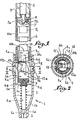
- the test tip shown comprises a hollow body or insulating head 1 constituted by a main cylindrical part 1 a that a conical part 1 b connects to a cylindrical end 1 c with small diameter inside which the tip is housed at rest metal 2.
- the latter is integral with an axial rod 2a, the rear end of which is screwed into a metal core 3.
- the core 3 provided with a cylindrical external profile, is notched from the rear (therefore opposite of the tip 2) of a transverse slot 3a which defines there two branches 3b, which are extended by two thin elastic blades 3c with cross section in the shape of an arc of a circle.
- the core 3 is retained inside an insulating tubular pusher 4 which extends rearwards well beyond the head 1 in which it is slidably mounted.
- This pusher is split transversely over a part of its length, as indicated in 4a, from its front end in which the core 3 is housed and the two branches 4b thus determined end in a flange 4c internally cut in an arc to come and engage in a 3d circular groove provided in a reduced diameter area of the unsplit front part of the core 3.
- the two branches defined by the slot 4a can open elastically to allow the establishment of the edges 4c around the groove 3d.
- the pusher 4 could be made in two pieces with a longitudinal joint which would be engaged on the core 3 and which would be welded or glued to one another.
- the pusher 4 is pushed backwards by a return spring 5 disposed around the rod 2a and which bears against an internal shoulder 1 d provided towards the junction of the parts 1 b and 1 c of the head 1, so that 'at rest the metal tip 2 is clearly erased inside the aforementioned part 1c.
- the rear part of the pusher 4 is provided with a diameter slightly smaller than that of the front part so as to determine a circular shoulder 4d which abuts against an internal rib 1e produced at the rear end of the head 1.
- the rear end of the pusher 4 is internally threaded to receive by screwing an insulating tubular button 6, the front end of which is secured by molding or otherwise from a cylindrical metal part or terminal 7, of slightly smaller diameter, drilled from the 'rear of a blind axial bore 7a into which opens a transverse perforation 7b threaded to receive a clamping screw 8.
- the conductor 9 associated with the test tip crosses the button 6, and its stripped end is tightened by the screw 8 to the interior of bore 7a.
- the front end of the part or terminal 7 has an axial extension 7c on which engages the hollow rear head 10a of a fuse cartridge 10 disposed inside the pusher 4.
- the other head or front head 10b of diameter much smaller than that of the first, is equipped with an axial striker 11 (see fig. 4); it engages between the blades 3c which are applied elastically against them.
- a locking pawl 12 mounted on a transverse axis 13 highly offset relative to the general axis of the whole of the touch point .
- This pawl is of flat shape, so as to be able to engage in the slot 3a of the core 3.
- Its axis 13 is mounted in bosses 4e provided inside the pusher and it carries a torsion spring 14 which recalls it in the sinistrorsum direction, its suitably curved ends being engaged in perforations of the pawl and of the branches 4b determined by the slot 4a of the pusher.
- the pawl 12 comprises, on the other hand, two noses 12a and 12b capable of coming to engage in an internal groove 1f provided in a part with a larger diameter 1 g of the head 1, depending on whether said pawl rotates in one direction or in the other from a normal service position, shown in fig. 1 and 2, regardless of the relative angular positions of the head 1 and the pusher 4.
- the pawl 12 bears against the end of the striker 11, which then is flush with the central boss 1 Oc of the head 1 Ob, so that it is not visible in the view of fig. 1 where the cartridge has not been cut.
- bosses 4e are established to form a stop for driving the cartridge 10 into the pusher 4, thereby limiting the screwing of the button 6.
- the overcurrent flows through the cartridge 10 which melts and protects the circuit. Its striker 11 switches the pawl 12 in the dextrorsum direction in fig. 1, so that, when one returns to the rest position, the tooth 12b of the latter engages in the groove 1f (position in FIG. 4) by blocking the pusher 4 relative to the body or head 1. The test probe then becomes unusable until the cartridge has been replaced.
- a lateral bulge 4f located at the right of the location of the cartridge 10.
- a discharge bulb 15 and a resistor 16 mounted in series l 'one after the other between the heads 10a and 1 Ob of the cartridge 10.
- the wall of the bulge 4f is secured to a first elastic blade 17 bent at right angles, one of its branches receiving one of the tips of the bulb 15, while the other forms lateral contact applied elastically against the head 10a.
- a second blade 18 cooperates with the opposite end of the bulb 15 and one of the ends of the resistor 16 is welded to it.
- the wall of the bulge 4f must be provided at the very least translucent, or else it must be brought to it a transparent window enabling the bulb 15 to be seen.
Landscapes
- Physics & Mathematics (AREA)
- General Physics & Mathematics (AREA)
- Measuring Leads Or Probes (AREA)
Claims (11)
Priority Applications (3)
| Application Number | Priority Date | Filing Date | Title |
|---|---|---|---|
| DE1982420088 DE97752T1 (de) | 1982-06-30 | 1982-06-30 | Tastspitze zur elektrischen oder aehnlichen messung. |
| EP19820420088 EP0097752B1 (de) | 1982-06-30 | 1982-06-30 | Tastspitze zur elektrischen oder ähnlichen Messung |
| DE8282420088T DE3263383D1 (en) | 1982-06-30 | 1982-06-30 | Probe for electrical or similar measurements |
Applications Claiming Priority (1)
| Application Number | Priority Date | Filing Date | Title |
|---|---|---|---|
| EP19820420088 EP0097752B1 (de) | 1982-06-30 | 1982-06-30 | Tastspitze zur elektrischen oder ähnlichen Messung |
Publications (2)
| Publication Number | Publication Date |
|---|---|
| EP0097752A1 EP0097752A1 (de) | 1984-01-11 |
| EP0097752B1 true EP0097752B1 (de) | 1985-05-02 |
Family
ID=8189967
Family Applications (1)
| Application Number | Title | Priority Date | Filing Date |
|---|---|---|---|
| EP19820420088 Expired EP0097752B1 (de) | 1982-06-30 | 1982-06-30 | Tastspitze zur elektrischen oder ähnlichen Messung |
Country Status (2)
| Country | Link |
|---|---|
| EP (1) | EP0097752B1 (de) |
| DE (2) | DE97752T1 (de) |
Families Citing this family (1)
| Publication number | Priority date | Publication date | Assignee | Title |
|---|---|---|---|---|
| DE4333662A1 (de) * | 1993-10-02 | 1995-04-06 | Gregor Adarczyn | Meßsonde |
Family Cites Families (5)
| Publication number | Priority date | Publication date | Assignee | Title |
|---|---|---|---|---|
| DE837728C (de) * | 1950-08-09 | 1952-05-02 | Ernst Krebs | Sicherheits-Fehlerortungsgriff |
| DE829325C (de) * | 1950-09-30 | 1952-01-24 | Ernst Jungnickel | Pruefspitze mit Verschwindekontakt |
| US3201746A (en) * | 1963-07-31 | 1965-08-17 | Crawford S Askew | Test probe with grappler |
| US4030030A (en) * | 1976-02-04 | 1977-06-14 | General Electric Company | Probe assembly for an electric meter |
| FR2408146A1 (fr) * | 1977-11-03 | 1979-06-01 | Capelin Sa | Pointe de touche |
-
1982
- 1982-06-30 DE DE1982420088 patent/DE97752T1/de active Pending
- 1982-06-30 EP EP19820420088 patent/EP0097752B1/de not_active Expired
- 1982-06-30 DE DE8282420088T patent/DE3263383D1/de not_active Expired
Also Published As
| Publication number | Publication date |
|---|---|
| EP0097752A1 (de) | 1984-01-11 |
| DE97752T1 (de) | 1985-03-14 |
| DE3263383D1 (en) | 1985-06-05 |
Similar Documents
| Publication | Publication Date | Title |
|---|---|---|
| EP2162955B1 (de) | Vorrichtung zur verriegelung einer steckervorrichtung | |
| EP1213792B1 (de) | Bistabile elektrische Anschlussklemme | |
| EP1173906B1 (de) | Sicherheitsfassung | |
| CA1244069A (fr) | Dispositif d'alimentation electrique a disjoncteur et prise electrique incorporant ce dispositif | |
| EP0547985B1 (de) | Sicherungseinsatz mit Ansprechanzeiger | |
| EP0097752B1 (de) | Tastspitze zur elektrischen oder ähnlichen Messung | |
| EP0773573B1 (de) | Sicherungseinsatz mit Ansprechanzeiger | |
| EP3419036B1 (de) | Befestigungsvorrichtung für elektrisches steuer- und/oder anzeigeorgan | |
| FR2920256A1 (fr) | Socle de prise verrouille | |
| FR2502339A1 (fr) | Pointe de touche pour mesures electriques et analogues | |
| CH703079B1 (fr) | Dispositif de fixation d'un bracelet interchangeable à une boîte de montre. | |
| FR2679474A1 (fr) | Appareil pour optimiser la perpendicularite d'un outil par rapport a la surface de la piece, lors d'un percage. | |
| EP3336982A1 (de) | Vorrichtung zur verteilung eines elektrischen stroms in mindestens zwei elektrogeräten | |
| FR2602617A1 (fr) | Dispositif de montage d'une cosse ou de tout autre element de connexion a une extremite d'un cable electrique | |
| EP1953779B1 (de) | Sicherunglasttrennschalter mit Schnellverschlusssicherung | |
| FR3028356A1 (fr) | Borne de connexion electrique a vis imperdable | |
| EP0592342A1 (de) | Sicherheitsverbinder für elektrische Verteilervorrichtung mit mehrfachen Abzweigungen | |
| EP0797271B1 (de) | Sockel für Stromsteckdose | |
| FR3001836A1 (fr) | Dispositif de fixation d'un appareillage electrique sur une paroi et procede de deconnexion associe | |
| EP1220255B1 (de) | Elektromagnetischer Schütz mit einer Kontaktbrücke und unabhängiger Feder | |
| FR2899728A1 (fr) | Prise de courant electrique a forces d'insertion et d'extraction controlees | |
| EP0986134A1 (de) | Verbinder für elektrische Leiter und Verbindungsvorrichtung mit einem solchen Verbinder | |
| FR2480999A1 (fr) | Perfectionnements aux ensembles de cartouche a fusibles et de dispositif de telesignalisation | |
| FR2842450A1 (fr) | Outil dynamometrique comportant un dispositif electrique de detection du declenchement | |
| FR2632458A1 (fr) | Connecteur electrique |
Legal Events
| Date | Code | Title | Description |
|---|---|---|---|
| PUAI | Public reference made under article 153(3) epc to a published international application that has entered the european phase |
Free format text: ORIGINAL CODE: 0009012 |
|
| AK | Designated contracting states |
Designated state(s): BE CH DE GB IT LI SE |
|
| 17P | Request for examination filed |
Effective date: 19840119 |
|
| ITF | It: translation for a ep patent filed | ||
| GRAA | (expected) grant |
Free format text: ORIGINAL CODE: 0009210 |
|
| DET | De: translation of patent claims | ||
| AK | Designated contracting states |
Designated state(s): BE CH DE GB IT LI SE |
|
| REF | Corresponds to: |
Ref document number: 3263383 Country of ref document: DE Date of ref document: 19850605 |
|
| PLBE | No opposition filed within time limit |
Free format text: ORIGINAL CODE: 0009261 |
|
| STAA | Information on the status of an ep patent application or granted ep patent |
Free format text: STATUS: NO OPPOSITION FILED WITHIN TIME LIMIT |
|
| 26N | No opposition filed | ||
| PG25 | Lapsed in a contracting state [announced via postgrant information from national office to epo] |
Ref country code: LI Effective date: 19880630 Ref country code: GB Effective date: 19880630 Ref country code: CH Effective date: 19880630 |
|
| PG25 | Lapsed in a contracting state [announced via postgrant information from national office to epo] |
Ref country code: SE Effective date: 19880701 |
|
| BERE | Be: lapsed |
Owner name: -LUCIEN FERRAZ & CIE- S.A. Effective date: 19880630 |
|
| GBPC | Gb: european patent ceased through non-payment of renewal fee | ||
| REG | Reference to a national code |
Ref country code: CH Ref legal event code: PL |
|
| PG25 | Lapsed in a contracting state [announced via postgrant information from national office to epo] |
Ref country code: DE Effective date: 19890301 |
|
| PG25 | Lapsed in a contracting state [announced via postgrant information from national office to epo] |
Ref country code: BE Effective date: 19890630 |
|
| EUG | Se: european patent has lapsed |
Ref document number: 82420088.5 Effective date: 19890510 |