EP0096476A2 - Ebener linearer Massstabraster für optische Umwandlung von Information - Google Patents
Ebener linearer Massstabraster für optische Umwandlung von Information Download PDFInfo
- Publication number
- EP0096476A2 EP0096476A2 EP83302712A EP83302712A EP0096476A2 EP 0096476 A2 EP0096476 A2 EP 0096476A2 EP 83302712 A EP83302712 A EP 83302712A EP 83302712 A EP83302712 A EP 83302712A EP 0096476 A2 EP0096476 A2 EP 0096476A2
- Authority
- EP
- European Patent Office
- Prior art keywords
- substrate
- disk
- light
- grating
- producing
- Prior art date
- Legal status (The legal status is an assumption and is not a legal conclusion. Google has not performed a legal analysis and makes no representation as to the accuracy of the status listed.)
- Withdrawn
Links
Images
Classifications
-
- G—PHYSICS
- G01—MEASURING; TESTING
- G01D—MEASURING NOT SPECIALLY ADAPTED FOR A SPECIFIC VARIABLE; ARRANGEMENTS FOR MEASURING TWO OR MORE VARIABLES NOT COVERED IN A SINGLE OTHER SUBCLASS; TARIFF METERING APPARATUS; MEASURING OR TESTING NOT OTHERWISE PROVIDED FOR
- G01D5/00—Mechanical means for transferring the output of a sensing member; Means for converting the output of a sensing member to another variable where the form or nature of the sensing member does not constrain the means for converting; Transducers not specially adapted for a specific variable
- G01D5/26—Mechanical means for transferring the output of a sensing member; Means for converting the output of a sensing member to another variable where the form or nature of the sensing member does not constrain the means for converting; Transducers not specially adapted for a specific variable characterised by optical transfer means, i.e. using infrared, visible, or ultraviolet light
- G01D5/32—Mechanical means for transferring the output of a sensing member; Means for converting the output of a sensing member to another variable where the form or nature of the sensing member does not constrain the means for converting; Transducers not specially adapted for a specific variable characterised by optical transfer means, i.e. using infrared, visible, or ultraviolet light with attenuation or whole or partial obturation of beams of light
- G01D5/34—Mechanical means for transferring the output of a sensing member; Means for converting the output of a sensing member to another variable where the form or nature of the sensing member does not constrain the means for converting; Transducers not specially adapted for a specific variable characterised by optical transfer means, i.e. using infrared, visible, or ultraviolet light with attenuation or whole or partial obturation of beams of light the beams of light being detected by photocells
- G01D5/36—Forming the light into pulses
- G01D5/38—Forming the light into pulses by diffraction gratings
-
- H—ELECTRICITY
- H03—ELECTRONIC CIRCUITRY
- H03M—CODING; DECODING; CODE CONVERSION IN GENERAL
- H03M1/00—Analogue/digital conversion; Digital/analogue conversion
- H03M1/10—Calibration or testing
- H03M1/1066—Mechanical or optical alignment
-
- H—ELECTRICITY
- H03—ELECTRONIC CIRCUITRY
- H03M—CODING; DECODING; CODE CONVERSION IN GENERAL
- H03M1/00—Analogue/digital conversion; Digital/analogue conversion
- H03M1/12—Analogue/digital converters
- H03M1/22—Analogue/digital converters pattern-reading type
- H03M1/24—Analogue/digital converters pattern-reading type using relatively movable reader and disc or strip
- H03M1/28—Analogue/digital converters pattern-reading type using relatively movable reader and disc or strip with non-weighted coding
- H03M1/30—Analogue/digital converters pattern-reading type using relatively movable reader and disc or strip with non-weighted coding incremental
Definitions
- This invention relates to a rotatable structure containing linear diffraction gratings and in particular to the use of such a structure (such as a disk) to optically decode angular information in a mechanical system.
- Rotatable holographic disks have been used for optical printers and for optically decoding the angular position of a rotating shaft in a mechanical system. However, they have not been used in a form where their centering is non-critical.
- Code disks to encode information wherein a number of annular bands possessing alternating opaque and transparent portions are circumferentially mounted at different radii along the disk are known in the art. In these disks, the lengths of the opaque regions dispersed with transparent regions along an annular band are used to determine the particular code to be transmitted by the disk. A light beam impinges the disk, the disk is rotated and the resulting interrupted pattern of light produces a desired code.
- These disks must be accurately centered and must remain centered to give high quality output signals. They are also subject to dust contamination and therefor must be kept clean.
- This invention makes use of our discovery that a multiplicity of linear diffraction gratings placed accurately on a disk (or a structure of any shape which functions like a disk) will diffract a light beam to a fixed point in space independently of the centering of the disk on the axis of rotation.
- This result is independent of the number of gratings placed on the disk, the ; orientation of the grating lines on the disk (with the limitation that each grating must be oriented in a fixed angular relationship to that angle of the mechanical shaft on which the disk is located and which that particular grating is to determine) and surprisingly even is independent of the overlapping of different gratings.
- one embodiment of the invention does not require focused light on the disk, the sensitivity of the system to dirt and dust is much less than that of a standard encoder disk.
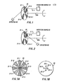
- a radiation source 10 produces a light beam 11-1 which is transmitted to a rotating disk 2 0.
- Disk 20 is of well-known design and is shown schematically for the purpose of simplicity. Formed on the surface of disk 20 are diffraction gratings 21-1 through 21-K where K is an integer representing the total number of diffraction grating facets formed on the disk. Typically K will depend upon the type of encoding to be incorporated in the disk. For normal encoding, these gratings (also called facets) are evenly spaced. However, these gratings can also be logarithmically spaced or non-linearly spaced in accordance with any desired rules.
- Light beam 11-1 from radiation source 10 passes through diffraction grating 21-1, for example, and then is diffracted.
- the diffracted beam 11-2 then sweeps an arc caused by the rotation of disk 20 about its axis 20a. A portion of the arc is subtended by detector 40.
- the light 11-1 from radiation source 10 is directed by diffraction grating 21-1 and the directed beam 11-2 is picked up by detector 40.
- Figure 2 illustrates a similar structure wherein the light beam 11-1 is reflected by diffraction grating 21-1 to form reflected beam 11-2.
- the reflected beam 11-2 is swept across detector 40 as the disk 20 is rotated about its axis 20a.
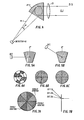
- FIGs 3A and 3B illustrate the structure of this invention in greater detail.
- eight diffraction grating facets 21-1 through 21-8 are formed on disk 20.
- Disk 20 has formed through its center an opening 22 through which a rotational shaft is mounted.
- opening 22 can be precisely centered in disk 20 as shown with opening 22-0.
- opening 22 can be centered above the precise center of disk 20 as shown by opening 22-1, to the left of this precise center as shown by opening 22-2, below this precise center as shown by opening 22-3 and to the right of this precise center as shown by opening 22-4 or in fact anywhere else.
- the encoding disk 20 when rotated, will produce a diffracted signal which strikes the detector 40 at precisely the correct time to produce an encoded output signal completely independent of the location of the opening 22 in the disk 20.
- the center of rotation is placed at such a point where the facet does not intercept the light beam (which would be the case for some facets were the center to be placed at 22-5), no light would be diffracted and therefor detector 40 would not receive a signal.
- the radiation 11-1 from source 10 is diffracted through an angle by the grating 21-k where k is an integer given by 1 ⁇ k ⁇ K..
- the plane of diffraction rotates.
- the plane of diffraction is the plane defined by light beam 11-1 and diffracted beam 11-2. Since a linear grating is used on disk 20 (i.e., each of gratings 21-k is linear), the plane of diffraction is orthogonal to the direction of the grating grooves and,we have discovered, is completely independent of the centering of the disk containing the grating.
- the diffracted light will intercept the detector 40 and produce an electrical signal that will indicate the angular position of the disk.
- signals are produced by detector 40 whose temporal spacing is determined solely by the accuracy of the original placement of the gratings on the encoded disk 20 and the angular velocity of the disk in the mechanical system.
- the signals produced by detectors 40 are independent of the centering of opening 22 in disk 20.
- diffraction gratings such as 21-1 through 21-K ( Figure 1) can be produced by the interference of two beams of mutually coherent light by a process of interference and the diffraction grating so produced is termed a holographic grating. Furthermore, by the nature of holography, the diffraction grating so produced can be superimposed to produce areas on a disk such as disk 20 that will diffract multiple spots that can be used to improve the numerical aperture of the diffracted radiation in a system where a large number of gratings are used.
- This multiple grating approach can also be used to produce phase signals through the use of multiple detectors for even higher resolution of the angular position of the. disk.
- parallel light beam 11-1 is focused by lens 25 onto diffraction grating 21-k to form a light beam 41-1 which converges onto detector 40 with angle 6.
- the spacing between the lines in the diffraction grating in one embodiment of this invention used with a photocopy machine was 1.27 microns. However, any spacing desired can be used compatible with the purposes for which the disk is to be used.
- the formation of a number of superimposed diffraction gratings on the disk does not degrade the output signals produced from the disk but rather allows the disk to be used to produce a large number of dots to cross a light detector during one rotation of the disk.
- Figure 6A illustrates the location of grating facets in different annular bands about a center of rotation of a disk for the purpose of providing coded signals.
- Figures 6B and 6C illustrate different facet constructions of use in this invention on a disk.
- Figure 7A illustrates a composite disk containing a selected family of facets utilizing single gratings, a pair of opposed facets utilizing a double grating (i.e. two gratings of different pitches superimposed on each other) and two opposed facets with three sets of superimposed gratings on each facet.
- Figure 7B illustrates the location of three detectors for detecting the light diffracted by the triple gratings illustrated in Figure 7A.
- the radiation can be acoustic and that the detector will then be a microphone.
- This technique also works with microwave radiation and also systems where the wave nature of particles, such as electrons, is utilized to diffract said particles.
- the number of detectors can be increased to provide greater accuracy of positional information.
- disk 20 has been illustrated in the drawings as circular, a non-circular substrate of material with diffraction gratings formed thereon can be used in place of a disk.
- a diffraction grating formed on a disk is used for two purposes.
- the diffraction grating diffracts a light beam which is then used to scan a photoconductive drum and which is modulated in accordance with information to be printed to produce, in a well-known manner, a replica of the information in a line on the photoconductive drum.
- the diffraction grating is used to control a servo controlled motor (typically a DC motor) to maintain a constant angular velocity of the disk in the printing system.
- a servo controlled motor typically a DC motor
- a holographic scanning disk (such as disk 20 in Figure 2 with twelve facets each subtending 30° arc and containing linear diffraction lines perpendicular to the diffraction lines shown in facets 21 of Figure 2) for use in printing information on a photoconductive drum has allocated a portion of the facet at the start of each scan for deflecting the laser beam (such as beam 11-1) to a light detector (such as detector 40). This light detector then sends a signal to a phase locked loop which controls the speed of a motor (not shown in Figure 2 but shown as motor 81 in Figure 9) in relation to a reference frequency derived from a crystal oscillator.
- a given number of pulses per second are derived from the rotating holographic disk.
- the pulse generated by the light detector at the start of each facet on the holographic disk is detected, this also indicates the start of a print line on the photoconductive drum.
- the beam (such as beam 11-1 in Figure 2) diffracted by the facet is then converted in a known manner, for example as disclosed in co-pending application Serial No. 237,833 filed 25 February 1981 and assigned to us, to form a straight line along the surface of the photoconductive drum.
- Application Serial No. 237,833 is hereby incorporated by reference.
- the techniques for carrying out the phase-lock loop control and for implementing the printing across the photoconductive drum are well known in the art.
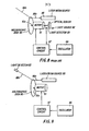
- Figure 8 illustrates in schematic block diagram form a motor control system of the prior art.
- motor 81 rotates holographic disk 85 in a manner well known in the prior art to thereby diffract the light beam 88a from laser beam source 88 to produce a sweeping beam 88b.
- Beam 88b is then converted to a straight line using, for example, the technique disclosed in patent application Serial No. 06/238,383 filed February 25, 1981 and assigned to us.
- the disclosure in application Serial No. 06/238,383 is hereby incorporated by reference.
- Light beam 88b from laser beam source 88 typically is swept along a line on a photoconductive drum while its intensity is modulated thereby to store information to be reproduced on a permanent medium in a manner well known in the art.
- motor 81 To ensure the proper placement on the photoconductive medium of the information to be stored, motor 81 must be driven at an accurate speed. This is done by deriving a sequence of pulses from the combination of optical disk 84, light source 82 and light detector 83.
- Optical disk 84 contains a series of transparent and opaque regions uniformly placed around a selected annulus equidistant from the center of rotation of disk 84.
- Light source 82 produces a continuous beam of light which is repetitively interrupted by the opaque portions of the annular ring formed on disk 84 as disk 84 rotates.
- Light detector 83 thus produces an output signal representing a sequence of pulses the frequency of which is proportional to the speed of motor 81.
- the pulse sequence from detector 83 is compared to a sequence of pulses from oscillator 86 (oscillator 86 typically comprises a crystal oscillator) in control circuit 87 and a difference signal is generated from this comparison and is used to either speed up or slow down motor 81 as appropriate.
- oscillator 86 typically comprises a crystal oscillator
- a control system which produces an output signal which is independent of the centering of the holographic disk 85 ( Figure 9) on the rotating shaft of motor 81.
- the light beam 88a from laser beam source 88 periodically strikes light detector 83 which is located to intercept light beam 88a at the start of each facet on holographic disk 85.
- a typical holographic disk will contain 12 facets, each subtending 30° of arc of the disk and each containing a linear diffraction grating the grating lines of which in one embodiment possess a pitch of 1.27 microns. Other pitches can also be used. Thus, twelve times each cycle of rotation of disk 85 beam 88b will strike light detector 83.
- the pulses produced by light detector 83 are transmitted to control circuit 87 which compares the frequency of the pulses from detector 83 to the frequency of the output signal from crystal oscillator 86. Control circuit 87 then produces a control signal to ensure that motor 81 is driven at the proper speed in response to these signals.
- the frequency of the output signal from light detector 83 is independent of the centering of holographic disk 85 on the axis of rotation 81a of motor 81 thus makes possible a substantial reduction in the cost of manufacture of the holographic scanning system of the type disclosed in the above-cited U.S. application Serial No. 06/238,383.
- the accuracy of the time interval between pulses from detector 83 depends upon the accuracy with which the gratings are placed on disk 85. These gratings can be placed very accurately on the disks using well known techniques.
- Prior art structures used a separate disk which had to be accurately centered on the motor shaft to make and break successive pulses of light from a light source to a light detector and then compare the light pulses passed by this disk to a known frequency.
- the system of our invention thus eliminates one optical disk and one light source compared to the prior art system, thus significantly reducing component costs. But equally important, the fact that the disk containing the linear diffraction grating does not have to be accurately centered on the motor shaft while still yielding pulses of uniform frequency from detector 83 produces an additional significant saving.
- the disk and system of this invention would have its accuracy unaffected by the eccentricity which might result from these side forces.
Landscapes
- Physics & Mathematics (AREA)
- General Physics & Mathematics (AREA)
- Optical Transform (AREA)
- Optical Recording Or Reproduction (AREA)
- Mechanical Optical Scanning Systems (AREA)
- Diffracting Gratings Or Hologram Optical Elements (AREA)
- Facsimile Scanning Arrangements (AREA)
Applications Claiming Priority (2)
| Application Number | Priority Date | Filing Date | Title |
|---|---|---|---|
| US06/377,648 US4528448A (en) | 1982-05-13 | 1982-05-13 | Plane linear grating for optically encoding information |
| US377648 | 1989-07-10 |
Publications (2)
| Publication Number | Publication Date |
|---|---|
| EP0096476A2 true EP0096476A2 (de) | 1983-12-21 |
| EP0096476A3 EP0096476A3 (de) | 1987-02-25 |
Family
ID=23489980
Family Applications (1)
| Application Number | Title | Priority Date | Filing Date |
|---|---|---|---|
| EP83302712A Withdrawn EP0096476A3 (de) | 1982-05-13 | 1983-05-13 | Ebener linearer Massstabraster für optische Umwandlung von Information |
Country Status (3)
| Country | Link |
|---|---|
| US (1) | US4528448A (de) |
| EP (1) | EP0096476A3 (de) |
| JP (1) | JPS58217913A (de) |
Cited By (8)
| Publication number | Priority date | Publication date | Assignee | Title |
|---|---|---|---|---|
| EP0220757A1 (de) * | 1985-10-01 | 1987-05-06 | Koninklijke Philips Electronics N.V. | Optisches Messgrössenumformerelement und Verschiebungsmessvorrichtung mit einem solchen Element |
| EP0212104A3 (en) * | 1985-06-07 | 1988-09-21 | Toshiba Kikai Kabushiki Kaisha | Method and apparatus for detecting absolute position |
| GB2210525A (en) * | 1987-09-30 | 1989-06-07 | Okuma Machinery Works Ltd | Optical encoder |
| EP0513427A1 (de) * | 1991-05-18 | 1992-11-19 | Dr. Johannes Heidenhain GmbH | Interferentielle Positionsmessvorrichtung |
| EP0637730A1 (de) * | 1993-07-31 | 1995-02-08 | Maz Mikroelectronik Anwendungszentrum Hamburg Gmbh | Winkelkodierer bzw. Winkelstellungsgeber bzw. Drehimpulsgeber |
| FR2779815A1 (fr) * | 1998-06-02 | 1999-12-17 | Ching Shun Wang | Moyens de calcul de type a focalisation |
| GB2396407A (en) * | 2002-12-19 | 2004-06-23 | Nokia Corp | Encoder |
| WO2007048611A1 (de) * | 2005-10-28 | 2007-05-03 | Hahn-Schickard-Gesellschaft für angewandte Forschung e.V. | Codierungselement für einen positionsgeber |
Families Citing this family (30)
| Publication number | Priority date | Publication date | Assignee | Title |
|---|---|---|---|---|
| JPS6070311A (ja) * | 1983-09-27 | 1985-04-22 | Mitsubishi Electric Corp | 光学式エンコ−ダ |
| ES8500524A1 (es) * | 1984-01-24 | 1984-10-01 | Carrio Llopis Miguel | Motor optoelectromagnetico |
| JPS6311822A (ja) * | 1986-07-02 | 1988-01-19 | Hitachi Ltd | 回折格子 |
| JPS6347616A (ja) * | 1986-08-15 | 1988-02-29 | Ricoh Co Ltd | 移動量測定方法 |
| JPS63271119A (ja) * | 1987-04-28 | 1988-11-09 | Hamamatsu Photonics Kk | 非接触型回転数検出装置 |
| US4985624A (en) * | 1988-05-11 | 1991-01-15 | Simmonds Precision Products, Inc. | Optical grating sensor and method of monitoring with a multi-period grating |
| US4874941A (en) * | 1988-05-11 | 1989-10-17 | Simmonds Precision Products, Inc. | Optical displacement sensor with a multi-period grating |
| US4849624A (en) * | 1988-06-24 | 1989-07-18 | The Boeing Company | Optical wavelength division multiplexing of digital encoder tracks |
| US5155605A (en) * | 1988-12-15 | 1992-10-13 | Hughes Aircraft Company | Rotating disk with spatially stabilized images |
| US5012090A (en) * | 1989-02-09 | 1991-04-30 | Simmonds Precision Products, Inc. | Optical grating sensor and method of monitoring having a multi-period grating |
| US5073710A (en) * | 1989-09-21 | 1991-12-17 | Copal Company Limited | Optical displacement detector including a displacement member's surface having a diffractive pattern and a holographic lens pattern |
| EP0455067B1 (de) * | 1990-05-03 | 2003-02-26 | F. Hoffmann-La Roche Ag | Mikrooptischer Sensor |
| US5162929A (en) * | 1991-07-05 | 1992-11-10 | Eastman Kodak Company | Single-beam, multicolor hologon scanner |
| CA2073409A1 (en) * | 1991-10-15 | 1993-04-16 | Paul F. Sullivan | Light beam position detection and control apparatus employing diffraction patterns |
| US5235180A (en) * | 1992-03-05 | 1993-08-10 | General Scanning, Inc. | Rotary motor having an angular position transducer and galvanometer scanning system employing such motor |
| DE69224514T2 (de) * | 1992-03-23 | 1998-06-18 | Erland Torbjoern Moelnlycke Sandstroem | Verfahren und Vorrichtung zur Erzeugung eines Bildes |
| EP0628791B1 (de) * | 1993-06-10 | 1999-09-08 | Canon Kabushiki Kaisha | Rotationserfassungsvorrichtung und zugehörige Skala |
| US5621548A (en) * | 1995-03-31 | 1997-04-15 | Eastman Kodak Company | Laser scanner employing a holeless hologon disk and fabrication method therefor |
| US5920380A (en) * | 1997-12-19 | 1999-07-06 | Sandia Corporation | Apparatus and method for generating partially coherent illumination for photolithography |
| CA2381675A1 (en) * | 1999-08-11 | 2001-02-15 | Jefferson E. Odhner | Direction of optical signals by a movable diffractive optical element |
| DE10233063A1 (de) * | 2002-07-19 | 2004-01-29 | Optolab Licensing Gmbh | Optisches Geberelement mit Positionierungsvorrichtung |
| DE10303038B4 (de) * | 2003-01-26 | 2006-11-30 | Samland, Thomas, Dipl.-Math. | Positionsmesseinrichtung |
| US7045769B2 (en) * | 2003-10-29 | 2006-05-16 | The Boeing Company | Optical encoders for position measurements |
| DE102005034166A1 (de) * | 2005-07-21 | 2007-02-01 | Osram Opto Semiconductors Gmbh | Gehäuse für ein elektromagnetische Strahlung emittierendes optoelektronisches Bauelement, elektromagnetische Strahlung emittierendes Bauelement und Verfahren zum Herstellen eines Gehäuses oder eines Bauelements |
| CN101636638B (zh) * | 2006-06-19 | 2013-06-05 | 杰斯集团公司 | 使用反射照明光的光学位置传感系统和方法 |
| US7595480B2 (en) * | 2006-10-16 | 2009-09-29 | Arcus Technology, Inc. | Optical encoder with encoder member having one or more digital diffractive optic regions |
| DE102010045355A1 (de) * | 2010-09-14 | 2012-03-15 | Festo Ag & Co. Kg | Positionsmesssystem und Verfahren zur Ermittlung einer Absolutposition |
| KR102543948B1 (ko) | 2016-05-17 | 2023-06-15 | 삼성전자주식회사 | 클럭 신호 생성기 및 기판 검사 장치 |
| US11434024B2 (en) | 2019-01-10 | 2022-09-06 | The Boeing Company | Automated engagement of and disengagement from a fitting |
| US10870180B2 (en) | 2019-01-10 | 2020-12-22 | The Boeing Company | Automated engagement and handling of a structure |
Family Cites Families (5)
| Publication number | Priority date | Publication date | Assignee | Title |
|---|---|---|---|---|
| US3544800A (en) * | 1968-11-20 | 1970-12-01 | Quantic Ind Inc | Optical apparatus for encoding angular movement of a rotating shaft |
| GB1353470A (en) * | 1970-10-19 | 1974-05-15 | Post D | Position measuring apparatus utilizing moire fringe multiplication |
| US3836257A (en) * | 1971-01-05 | 1974-09-17 | Canon Kk | Method for optical detection and/or measurement of movement of diffraction grating |
| US3862428A (en) * | 1973-10-11 | 1975-01-21 | United Aircraft Corp | Holographic spatial encoder |
| US4167666A (en) * | 1978-04-28 | 1979-09-11 | The United States Of America As Represented By The Secretary Of The Army | Multi-grating attenuator for high power pulsed laser beams |
-
1982
- 1982-05-13 US US06/377,648 patent/US4528448A/en not_active Expired - Fee Related
-
1983
- 1983-05-13 JP JP58082882A patent/JPS58217913A/ja active Pending
- 1983-05-13 EP EP83302712A patent/EP0096476A3/de not_active Withdrawn
Cited By (11)
| Publication number | Priority date | Publication date | Assignee | Title |
|---|---|---|---|---|
| EP0212104A3 (en) * | 1985-06-07 | 1988-09-21 | Toshiba Kikai Kabushiki Kaisha | Method and apparatus for detecting absolute position |
| EP0220757A1 (de) * | 1985-10-01 | 1987-05-06 | Koninklijke Philips Electronics N.V. | Optisches Messgrössenumformerelement und Verschiebungsmessvorrichtung mit einem solchen Element |
| GB2210525A (en) * | 1987-09-30 | 1989-06-07 | Okuma Machinery Works Ltd | Optical encoder |
| GB2210525B (en) * | 1987-09-30 | 1991-11-20 | Okuma Machinery Works Ltd | Optical encoder |
| EP0513427A1 (de) * | 1991-05-18 | 1992-11-19 | Dr. Johannes Heidenhain GmbH | Interferentielle Positionsmessvorrichtung |
| US5428445A (en) * | 1991-05-18 | 1995-06-27 | Dr. Johannes Heidenhain Gmbh | Interferential position measuring device |
| EP0637730A1 (de) * | 1993-07-31 | 1995-02-08 | Maz Mikroelectronik Anwendungszentrum Hamburg Gmbh | Winkelkodierer bzw. Winkelstellungsgeber bzw. Drehimpulsgeber |
| FR2779815A1 (fr) * | 1998-06-02 | 1999-12-17 | Ching Shun Wang | Moyens de calcul de type a focalisation |
| GB2396407A (en) * | 2002-12-19 | 2004-06-23 | Nokia Corp | Encoder |
| US7183536B2 (en) | 2002-12-19 | 2007-02-27 | Nokia Corporation | Motion encoder |
| WO2007048611A1 (de) * | 2005-10-28 | 2007-05-03 | Hahn-Schickard-Gesellschaft für angewandte Forschung e.V. | Codierungselement für einen positionsgeber |
Also Published As
| Publication number | Publication date |
|---|---|
| US4528448A (en) | 1985-07-09 |
| EP0096476A3 (de) | 1987-02-25 |
| JPS58217913A (ja) | 1983-12-19 |
Similar Documents
| Publication | Publication Date | Title |
|---|---|---|
| US4528448A (en) | Plane linear grating for optically encoding information | |
| US5132952A (en) | System for reproducing pulse time modulated wave forms stored along a diffractive track | |
| RU2017235C1 (ru) | Оптически считываемый носитель записи информации, устройство для копирования носителя записи информации и устройства для оптического считывания и записи информации | |
| US5101102A (en) | Rotary encoder having a plurality of beams emitted by a diffraction grating | |
| US4999482A (en) | Optical scanning system for a bar code reader | |
| US4556966A (en) | Information carrier disk with angular coding means and a system for driving said disk in rotation | |
| US5091798A (en) | Diffraction grating for optical scanning | |
| US4523093A (en) | Scanning beam reference and read system | |
| US5159192A (en) | Encoder and scanning system using a scale having a non-uniform pitch | |
| US4540247A (en) | Hologram scanner | |
| EP0354028B1 (de) | Vorrichtung zum Abtasten mittels Strahlung | |
| US4470659A (en) | Light beam scanning apparatus | |
| US5182743A (en) | Optical disk arrangement with diffractive tracks allowing positional control | |
| US5196956A (en) | Beam deflector and laser beam printer using only two inclined reflecting surfaces | |
| US4478480A (en) | Holographic scanner spinner wobble correction system | |
| JP3591942B2 (ja) | 変位情報検出装置 | |
| JPH05256666A (ja) | ロータリーエンコーダー | |
| EP0278332B1 (de) | Strahlablenker und damit arbeitender Laserdrucker | |
| EP0069306B1 (de) | Hologrammabtaster | |
| JPH0843135A (ja) | 光回折光学結像素子を有するエンコーダ | |
| JPS60100013A (ja) | 回転検出器 | |
| JP2582436B2 (ja) | レーザ光走査装置 | |
| US4571020A (en) | Hologram light deflector | |
| JP2540113B2 (ja) | エンコ―ダ | |
| JPS5915221A (ja) | 光走査装置 |
Legal Events
| Date | Code | Title | Description |
|---|---|---|---|
| PUAI | Public reference made under article 153(3) epc to a published international application that has entered the european phase |
Free format text: ORIGINAL CODE: 0009012 |
|
| AK | Designated contracting states |
Designated state(s): DE FR GB IT NL |
|
| RAP1 | Party data changed (applicant data changed or rights of an application transferred) |
Owner name: BENSON, INC. |
|
| PUAL | Search report despatched |
Free format text: ORIGINAL CODE: 0009013 |
|
| AK | Designated contracting states |
Kind code of ref document: A3 Designated state(s): DE FR GB IT NL |
|
| STAA | Information on the status of an ep patent application or granted ep patent |
Free format text: STATUS: THE APPLICATION IS DEEMED TO BE WITHDRAWN |
|
| 18D | Application deemed to be withdrawn |
Effective date: 19870826 |
|
| RIN1 | Information on inventor provided before grant (corrected) |
Inventor name: DOGGETT, DAVID E. |