EP0096036B1 - Agencement de production de dalles longitudinales en beton - Google Patents
Agencement de production de dalles longitudinales en beton Download PDFInfo
- Publication number
- EP0096036B1 EP0096036B1 EP19820902103 EP82902103A EP0096036B1 EP 0096036 B1 EP0096036 B1 EP 0096036B1 EP 19820902103 EP19820902103 EP 19820902103 EP 82902103 A EP82902103 A EP 82902103A EP 0096036 B1 EP0096036 B1 EP 0096036B1
- Authority
- EP
- European Patent Office
- Prior art keywords
- beams
- pipes
- rail
- arrangement
- concrete
- Prior art date
- Legal status (The legal status is an assumption and is not a legal conclusion. Google has not performed a legal analysis and makes no representation as to the accuracy of the status listed.)
- Expired
Links
Images


Classifications
-
- B—PERFORMING OPERATIONS; TRANSPORTING
- B28—WORKING CEMENT, CLAY, OR STONE
- B28B—SHAPING CLAY OR OTHER CERAMIC COMPOSITIONS; SHAPING SLAG; SHAPING MIXTURES CONTAINING CEMENTITIOUS MATERIAL, e.g. PLASTER
- B28B7/00—Moulds; Cores; Mandrels
- B28B7/24—Unitary mould structures with a plurality of moulding spaces, e.g. moulds divided into multiple moulding spaces by integratable partitions, mould part structures providing a number of moulding spaces in mutual co-operation
- B28B7/241—Detachable assemblies of mould parts providing only in mutual co-operation a number of complete moulding spaces
- B28B7/246—Detachable assemblies of mould parts providing only in mutual co-operation a number of complete moulding spaces for making oblong objects, e.g. girders
Definitions
- the present invention relates to an arrangement for casting in a mould of so called battery design longitudinal concrete bodies with a high degree of linearity, said battery comprising a series of beams running in parallel to each other and constituting the lower boundary surface of the mould, and on the top of adjacent beams longitudinally extending pipes constituting the lateral boundary sides.
- the object of the present invention is to obtain a possibility of producing longitudinal concrete bodies with a high degree of linearity in an economical and rational way.
- the Swedish patent application no 8001663-7 describes a method for producing concrete floors of high quality as regards planeness and rational construction, using slide tracks for the vibrating beams employed in the process of producing the floor by way of permanently ramaining moulds.
- slide tracks for the vibrating beams employed in the process of producing the floor by way of permanently ramaining moulds.
- Moulds can be produced from thin metal sheeting bent to the required cross-sectional shape. The sections are then connected by point-welding. This gives rise to heat stresses causing deformation of the sheets with disastrous consequences for the use of the resulting slabs. Also injection-moulded aluminium has been tried but after handling, the condition of this product becomes quite bad. Once this is the case, it is less possible to produce correct slabs. In addition aluminium is, after all, subject to the disadvantage that it is attacked by concrete, so that the surface of the product becomes corroded and thereby rough.
- the pipes have a substantially circular cross-section with a flattened underside, each pipe on its flattened underside being provided with a rail, which has a cross-section of an upside-down T, said rail being broken at a number of points at mutually equal distances; that the beams are arranged with some gap therebetween; that said pipes are placed on top of adjacent beams so that said rail is arranged in said gap; that plates each having a Y-shaped recess are placed between the top edges of adjacent beams, and at the same distances from each other as the interruptions in the rails, said recesses being arranged to receive the leg of the T-rail.
- Battery moulding referred to above and in the following means that several bodies are produced simultaneously in a large mould. As a result moulding costs and labour can be reduced.
- concrete bodies particularly screed slabs can be produced having a high degree of linearity.
- the frame 1 denotes a beam, a number of such beams 1 having been placed in a frame (not shown) consisting of strong beams.
- the length of the frame which normally constitutes the length of the beams, is 5-10 m, and the width of the frame is 1-2 m.
- the beams are placed at a distance from each other and extend parallel to the longitudinal sides of the frame.
- the frame with its beams 1 form a bed of beams 1, which forms a lower boundary surface in the mould.
- the choice of material, length, and width of the frame with its beams 1 may be made entirely according to the capacity of the lifting devices used for handling the arrangement during production.
- On the top of the beams 1 longitudinally extending pipes 2 are placed on the top of the beams 1 .
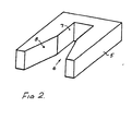
- the pipes 2 have a substantially circular cross-section, and have been levelled off somewhat, thereby showing a flat, longitudinally extending surface 3.
- This surface 3 covers 30 to 90 degrees of the central angle.
- a rail 4 having the shape of an upside down T is secured, i.e. the leg of the T-rail 4 is attached along a longitudinally extending line in the centre of the surface 3.
- the rail 4 is broken by gaps at equal distances. These breaks, or gaps, occur e.g. at a rate of one per meter, and with a length of e.g. 5 cm. These measures can be varied within wide limits, and the dimensions herein given is only to facilitate the understanding of the following.
- the width of the T corresponds substantially to the distance between two beams 1, as shown in Fig. 1.
- top plates 5 are arranged between each beam 1 in the bed of beams. These top plates 5 are placed at equal distances from each other corresponding to the distances between the breaks in the rail 4. The length of the top plates 5 does not exceed the length of the breaks. The top edges of the top plates 5 are further placed edge to edge to the top edges of the beams 1.
- the top plates 5 have a Y-shaped recess, generally denoted 6 therein.
- the recess 6 being Y-shaped has an outer part 8 and an inner part 7, the latter fitting the leg of the T-shaped rail 4.
- the outer expanding part 8 of the recess 6 is used for guiding the said leg of the T-rail 4, in the case where non-linearities in the pipe 2 may prevent a simple insertion, as follows.
- the pipes are placed on top of the beams 1 with their levelled surfaces 3 facing the beams 1.
- the gaps in the rail 4 are placed above the top plates 5, whereupon the pipes 2 and the rail 4 are put down into the gaps between the beams 1.
- the pipes 2 are locked by pushing them axially, whereby the rails 4 fit into the recesses 6, and particularly the parts 7, and lock therein.
- the pipes 2 now form the lateral sides of the mould.
- the bed of beams 1 is made of strong beams and that the planeness is accurately adjusted.
- the entire bed of beams is then placed on three or several bearing brackets which in turn are provided with vibration-generating devices, all with a view to ensuring satisfactory casting using concrete.
Landscapes
- Engineering & Computer Science (AREA)
- Manufacturing & Machinery (AREA)
- Chemical & Material Sciences (AREA)
- Ceramic Engineering (AREA)
- Mechanical Engineering (AREA)
- On-Site Construction Work That Accompanies The Preparation And Application Of Concrete (AREA)
- Forms Removed On Construction Sites Or Auxiliary Members Thereof (AREA)
- Devices For Post-Treatments, Processing, Supply, Discharge, And Other Processes (AREA)
- Road Paving Machines (AREA)
Claims (1)
- Agencement pour la coulée, dans un moule d'une conception dite en batterie, de masses longitudinales en béton, présentant un degré élevé de linéarité, cette batterie comprenant une série de poutres (1) disposées parallèlement entre elles et constituant la surface de délimitation inférieure du moule, et sur le haut de poutres (1) adjacentes, des conduits longitudinaux (2) constituant les parois de délimitation latérales, caractérisé en ce que les conduits (2) ont une section droite essentiellement circulaire, avec une base aplatie (3), chaque conduit (2) étant pourvu, sur sa base aplatie (3), d'un rail (4) qui a une section droite en forme de T renversé, ce rail étant interrompu en un certain nombre de points sur des distances égales; en ce que les poutres (1) sont disposées en prévoyant un certain intervalle entre elles; en ce que les conduits (2) sont placés sur le haut de poutres adjacentes (1) de manière que le rail (4) susdit soit disposé dans cet intervalle; et en ce que des plaques (5) présentant chacune une cavité en forme de Y (6, 7, 8) sont placées entre les bords supérieurs des poutres adjacentes (1) et à la même distance entre elles que les interruptions prévues dans les rails (4), cette cavité (6, 7, 8) étant agencée pour recevoir la branche verticale du rail en T (4).
Priority Applications (1)
| Application Number | Priority Date | Filing Date | Title |
|---|---|---|---|
| AT82902103T ATE20546T1 (de) | 1981-07-10 | 1982-07-09 | Einrichtung zur herstellung von laenglichen platten aus beton. |
Applications Claiming Priority (2)
| Application Number | Priority Date | Filing Date | Title |
|---|---|---|---|
| SE8104292A SE447004B (sv) | 1981-07-10 | 1981-07-10 | Anordning for att i en form av s k batteriutforande gjuta langstreckta kroppar av betong |
| SE8104292 | 1981-07-10 |
Publications (2)
| Publication Number | Publication Date |
|---|---|
| EP0096036A1 EP0096036A1 (fr) | 1983-12-21 |
| EP0096036B1 true EP0096036B1 (fr) | 1986-06-25 |
Family
ID=20344230
Family Applications (1)
| Application Number | Title | Priority Date | Filing Date |
|---|---|---|---|
| EP19820902103 Expired EP0096036B1 (fr) | 1981-07-10 | 1982-07-09 | Agencement de production de dalles longitudinales en beton |
Country Status (7)
| Country | Link |
|---|---|
| EP (1) | EP0096036B1 (fr) |
| JP (1) | JPS58501081A (fr) |
| DE (1) | DE3271832D1 (fr) |
| DK (1) | DK152793C (fr) |
| FI (1) | FI72371C (fr) |
| SE (1) | SE447004B (fr) |
| WO (1) | WO1983000177A1 (fr) |
Families Citing this family (1)
| Publication number | Priority date | Publication date | Assignee | Title |
|---|---|---|---|---|
| US4950434A (en) * | 1985-04-29 | 1990-08-21 | Permaban Southeast, Inc. | Arrangement for the production of longitudinal screed slabs consisting of concrete |
Family Cites Families (5)
| Publication number | Priority date | Publication date | Assignee | Title |
|---|---|---|---|---|
| US1900346A (en) * | 1933-03-07 | Roof and floor structure | ||
| CH568457A5 (en) * | 1973-09-11 | 1975-10-31 | Sonderegger Emil | Frame for concrete ceiling mfr - has trimming pole drawn over rails with level determined by spindle and pipe on formwork |
| SE404996B (sv) * | 1978-01-13 | 1978-11-13 | Straengbetong Ab | Anordning vid betonggjutformar |
| DE2912906A1 (de) * | 1979-03-31 | 1980-10-16 | Rilco Maschf | Hoehenverstelleinrichtung fuer abziehbohle |
| EP0027779A1 (fr) * | 1979-10-22 | 1981-04-29 | Paul Terraillon | Appareillage de coffrage pour couler directement sur le sol des dalles de béton précises |
-
1981
- 1981-07-10 SE SE8104292A patent/SE447004B/sv not_active IP Right Cessation
-
1982
- 1982-07-09 WO PCT/SE1982/000240 patent/WO1983000177A1/fr active IP Right Grant
- 1982-07-09 JP JP50214582A patent/JPS58501081A/ja active Pending
- 1982-07-09 EP EP19820902103 patent/EP0096036B1/fr not_active Expired
- 1982-07-09 DE DE8282902103T patent/DE3271832D1/de not_active Expired
-
1983
- 1983-02-28 DK DK100883A patent/DK152793C/da not_active IP Right Cessation
- 1983-08-09 FI FI832860A patent/FI72371C/fi not_active IP Right Cessation
Also Published As
| Publication number | Publication date |
|---|---|
| EP0096036A1 (fr) | 1983-12-21 |
| SE8104292L (sv) | 1983-01-11 |
| SE447004B (sv) | 1986-10-20 |
| DE3271832D1 (en) | 1986-07-31 |
| JPS58501081A (ja) | 1983-07-07 |
| WO1983000177A1 (fr) | 1983-01-20 |
| DK100883A (da) | 1983-02-28 |
| FI72371C (fi) | 1987-05-11 |
| DK152793C (da) | 1988-10-10 |
| FI832860A (fi) | 1983-08-09 |
| DK100883D0 (da) | 1983-02-28 |
| FI72371B (fi) | 1987-01-30 |
| DK152793B (da) | 1988-05-16 |
| FI832860A0 (fi) | 1983-08-09 |
Similar Documents
| Publication | Publication Date | Title |
|---|---|---|
| US4123034A (en) | Box form for concrete culvert | |
| US2916795A (en) | Apparatus for molding reinforced concrete building slabs, columns and girders | |
| KR101916744B1 (ko) | 강성이 향상된 교량 상부 구조물 및 이를 이용한 교량의 시공방법 | |
| US4274824A (en) | Mold box apparatus | |
| US2874442A (en) | Apparatus for making concrete structural shapes | |
| EP0380149B1 (fr) | Système de coffrage pour dalles | |
| EP0096036B1 (fr) | Agencement de production de dalles longitudinales en beton | |
| CN208586529U (zh) | 一种坡度预制梁支座调平装置 | |
| US4950434A (en) | Arrangement for the production of longitudinal screed slabs consisting of concrete | |
| EP0327563B1 (fr) | Coffrage servant a former des briques ou des blocs in situ | |
| US3023477A (en) | One piece casting form | |
| US2782478A (en) | Sectional hot top | |
| CN209798958U (zh) | 底板后浇带排水沟浇筑系统及排水沟定型吊模 | |
| CN109914571B (zh) | 一种地下室排水沟模架体系、浇筑系统及施工方法 | |
| JP5685745B2 (ja) | 内底に勾配調整コンクリート打するプレキャスト有底側溝 | |
| US3030688A (en) | Molding apparatus | |
| CN211030568U (zh) | 用于预制梁生产的台座 | |
| CN208072217U (zh) | 一种便捷式摊铺轨道 | |
| CN216839920U (zh) | 一种混凝土外墙的接茬连接结构 | |
| GB1502133A (en) | Composite decks | |
| EP2746016A1 (fr) | Méthode pour la fabrication de panneau préfabriqué pour construction de cuve circulaire et moule correspondant | |
| CN211278957U (zh) | 一种建筑用模台模具 | |
| CN114434612B (zh) | 一种变参数预制t梁模板组件 | |
| US2129208A (en) | Concrete form or mold | |
| CN213038172U (zh) | 一种用于调节预制t梁梁靴坡度的结构 |
Legal Events
| Date | Code | Title | Description |
|---|---|---|---|
| PUAI | Public reference made under article 153(3) epc to a published international application that has entered the european phase |
Free format text: ORIGINAL CODE: 0009012 |
|
| 17P | Request for examination filed |
Effective date: 19830801 |
|
| AK | Designated contracting states |
Designated state(s): AT CH DE FR GB LI LU NL |
|
| GRAA | (expected) grant |
Free format text: ORIGINAL CODE: 0009210 |
|
| RAP1 | Party data changed (applicant data changed or rights of an application transferred) |
Owner name: PERMABAN AB |
|
| AK | Designated contracting states |
Kind code of ref document: B1 Designated state(s): AT CH DE FR GB LI LU NL |
|
| REF | Corresponds to: |
Ref document number: 20546 Country of ref document: AT Date of ref document: 19860715 Kind code of ref document: T |
|
| REF | Corresponds to: |
Ref document number: 3271832 Country of ref document: DE Date of ref document: 19860731 |
|
| ET | Fr: translation filed | ||
| PLBE | No opposition filed within time limit |
Free format text: ORIGINAL CODE: 0009261 |
|
| STAA | Information on the status of an ep patent application or granted ep patent |
Free format text: STATUS: NO OPPOSITION FILED WITHIN TIME LIMIT |
|
| 26N | No opposition filed | ||
| EPTA | Lu: last paid annual fee | ||
| PGFP | Annual fee paid to national office [announced via postgrant information from national office to epo] |
Ref country code: FR Payment date: 19920617 Year of fee payment: 11 |
|
| PGFP | Annual fee paid to national office [announced via postgrant information from national office to epo] |
Ref country code: GB Payment date: 19920709 Year of fee payment: 11 |
|
| PGFP | Annual fee paid to national office [announced via postgrant information from national office to epo] |
Ref country code: AT Payment date: 19920729 Year of fee payment: 11 |
|
| PGFP | Annual fee paid to national office [announced via postgrant information from national office to epo] |
Ref country code: NL Payment date: 19920731 Year of fee payment: 11 Ref country code: LU Payment date: 19920731 Year of fee payment: 11 |
|
| PGFP | Annual fee paid to national office [announced via postgrant information from national office to epo] |
Ref country code: DE Payment date: 19920825 Year of fee payment: 11 |
|
| PGFP | Annual fee paid to national office [announced via postgrant information from national office to epo] |
Ref country code: CH Payment date: 19921023 Year of fee payment: 11 |
|
| PG25 | Lapsed in a contracting state [announced via postgrant information from national office to epo] |
Ref country code: LU Free format text: LAPSE BECAUSE OF NON-PAYMENT OF DUE FEES Effective date: 19930709 Ref country code: GB Effective date: 19930709 Ref country code: AT Effective date: 19930709 |
|
| PG25 | Lapsed in a contracting state [announced via postgrant information from national office to epo] |
Ref country code: LI Effective date: 19930731 Ref country code: CH Effective date: 19930731 |
|
| PG25 | Lapsed in a contracting state [announced via postgrant information from national office to epo] |
Ref country code: NL Effective date: 19940201 |
|
| GBPC | Gb: european patent ceased through non-payment of renewal fee |
Effective date: 19930709 |
|
| NLV4 | Nl: lapsed or anulled due to non-payment of the annual fee | ||
| PG25 | Lapsed in a contracting state [announced via postgrant information from national office to epo] |
Ref country code: FR Effective date: 19940331 |
|
| REG | Reference to a national code |
Ref country code: CH Ref legal event code: PL |
|
| PG25 | Lapsed in a contracting state [announced via postgrant information from national office to epo] |
Ref country code: DE Effective date: 19940401 |
|
| REG | Reference to a national code |
Ref country code: FR Ref legal event code: ST |