EP0095988A1 - Door lock, especially for vehicles - Google Patents
Door lock, especially for vehicles Download PDFInfo
- Publication number
- EP0095988A1 EP0095988A1 EP83401123A EP83401123A EP0095988A1 EP 0095988 A1 EP0095988 A1 EP 0095988A1 EP 83401123 A EP83401123 A EP 83401123A EP 83401123 A EP83401123 A EP 83401123A EP 0095988 A1 EP0095988 A1 EP 0095988A1
- Authority
- EP
- European Patent Office
- Prior art keywords
- bolt
- lever
- lock
- hand
- locking member
- Prior art date
- Legal status (The legal status is an assumption and is not a legal conclusion. Google has not performed a legal analysis and makes no representation as to the accuracy of the status listed.)
- Granted
Links
Images


Classifications
-
- E—FIXED CONSTRUCTIONS
- E05—LOCKS; KEYS; WINDOW OR DOOR FITTINGS; SAFES
- E05B—LOCKS; ACCESSORIES THEREFOR; HANDCUFFS
- E05B81/00—Power-actuated vehicle locks
- E05B81/12—Power-actuated vehicle locks characterised by the function or purpose of the powered actuators
- E05B81/20—Power-actuated vehicle locks characterised by the function or purpose of the powered actuators for assisting final closing or for initiating opening
Definitions
- the present invention relates to door locks, in particular for a motor vehicle, of the type comprising a bolt and a keeper movable relative to one another so as to be able to hang on or free from each other when the blocking or unlocking of the lock, the bolt being associated with a locking member which is intended to retain the bolt in its position hooked on the strike and which is controlled by motor means intended to release it from the bolt against an elastic return member of this locking member, said motor means being further coupled to the bolt by a transmission to bring the bolt into its hooked position during the final phase of blocking the lock.
- the weight gain sought by all manufacturers to reduce energy consumption results in a reduction in the mass of the doors, which reduces the inertia forces due to slamming of the door and therefore results in less good compression of the seal, accentuating the faults mentioned above.
- Locks have already been developed capable of automatically closing a car trunk lid in the final phase of its movement. Such locks are described in particular in patents US-A-3,378,291 and US-A-2,950,138.
- the invention aims to remedy these drawbacks.
- a lock of the type indicated above which is characterized in that the bolt and the locking member are both articulated on the housing containing the lock mechanism and in that said motor means comprise a locking member.
- 'drive which is arranged to act separately and successively on the one hand on said locking member when unlocking the lock and on the other hand on said transmission for blocking thereof.
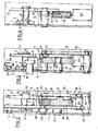
- the lock according to the invention comprises a housing 1 which has in section roughly the shape of a U and in which is housed a bolt 2 mounted articulated around a pin 3 fixed on the bottom of the case. It should be noted that on all F ig., The cover of the housing 1 has not been shown.
- the bolt 2 generally has a triangular shape, one of the vertices of which is articulated on the pin 3 and which, opposite this vertex, has a notch 4 delimiting on the bolt two branches 5 and 6 located on either side of this notch.
- the branch 6 is provided with a heel 7 which extends beyond the outline of the triangle formed by the bolt 2. This same branch 6 carries a locking lug 8.
- a passage 9 which widens towards the side of the housing and in which is intended to penetrate a keeper 10 to be retained in the notch 4 of the bolt when the latter is in its locking position of the lock.
- the bolt 2 cooperates with locking means 11 which firstly comprise a locking lever 12 generally having the shape of an S.
- This lever is articulated on a pin 13 fixed in the housing and has a first locking branch 14 proper, intended to cooperate with the lug 8 of the bolt and comprising two adjacent notches 15 and 16, one 15 called “first notch” and the other 16 called “second notch”.
- the first branch of the locking lever 12 is extended by a connecting portion 17 extending at approximately right angles to this branch and which connects the latter to a second branch 18 for actuating this locking lever.
- This second branch extends approximately at right angles to the connection portion, but in the opposite direction with respect to the first branch, the connection zone being crossed by the articulation pin 13.
- an actuating tab 19 which is folded laterally relative to the general plane of the lever 12 and whose function is essentially to ensure the possibility of opening of backup of the lock as will be explained later.
- the locking means 11 also comprise a toothed wheel 20 rotatably mounted on a pin 21 fixed in the housing, this wheel meshing with an endless screw 22 which is coupled to the shaft of an electric drive motor 23.
- This wheel is provided with a profiled boss 24 forming a pusher which is in the form of a projection raised on one of the faces of the wheel.
- This boss is intended to cooperate, during the rotation of the wheel 20, with an operating lever 25 which is articulated around a pin 26 fixed on the bottom of the housing 1.
- This lever bears at its opposite end with respect to the spindle 26, a roller 27 with which the boss 24 can come into contact during part of its path traveled during the rotation of the wheel 20.
- the operating lever 25 has a lateral wing 28, the outer edge of which forms a cam track 29 constitutes by a notch-shaped part with a rounded bottom to which a projection also with a rounded shape is adjacent.
- the cam track 29 cooperates with a roller 31 which is carried by a transmission lever 30 articulated on the bottom of the housing by means of a pin 3 2 .
- the transmission lever has approximately the shape of an L and is articulated around the pin 32 approximately in the middle of the large branch of this L.
- the small branch of the transmission lever 30 carries at its free end a another roller 33 which is intended to come into contact with the heel 7 of the bolt 2 during the operation of the lock.
- rollers 27, 31 and 33 are mounted to rotate on the corresponding levers respectively by means of pivots 34, 35 and 36.
- the lever 25 is permanently biased towards a fixed stop 37 which is integral with the housing 1, under the action of a spring 38 via a part of the transmission lever 30, resting on its turn by the roller 31 on this lever 25.
- the spring 38 of the helical type is mounted around the spindle 32 and is hooked on the one hand at 39 on the housing 1 and on the other hand at 40 on the corresponding branch of the lever 30.
- the locking lever 12 is provided with a helical spring 41 which is mounted around the spindle 13 and which is hooked by one of its ends on this lever and which by its other end bears against a wall side of the housing 1.
- the locking lever 12 is biased clockwise, as seen in Fig.l and 5 A to 5 D.
- a third floating spring 42 mounted is associated with the bolt 2 to urge it in the direction of the opening of the lock, this spring being hung on the one hand on a side wall of the housing 1 and on the other hand in the edge lateral of the bolt 2, respectively in points 43 and 44.
- the electric motor 23 is mounted in a supply circuit connected to a voltage source (not shown) which can be the vehicle battery.
- a voltage source (not shown) which can be the vehicle battery.
- This motor is mounted in series with a first switch 45 which is fixedly mounted in the housing and which is provided with a feeler 46 placed on the path of the boss 24 of the wheel 20.
- the movable contact of this switch is placed in a position corresponding to the locking of the lock and this position is called “position 1" in the following description, its opposite position being called “O".
- the electric motor 23 is also mounted in series with another switch 47 fixed in the housing and the movable contact of which is provided with a feeler 48 which is intended to be actuated by the edge of the bolt 2 when the latter is in the position corresponding to the "first notch".
- a feeler 48 which is intended to be actuated by the edge of the bolt 2 when the latter is in the position corresponding to the "first notch".
- the lock can be controlled by a device making it possible to actuate the lock both from inside and from outside the vehicle.
- the bolt 2 is in its high position in which on the one hand, the locking pin 8 is released from the notches 15 and 16 of the locking lever 12 and on the other hand, the roller 33 is supported in the rounded portion of the heel 7 of the bolt 2.
- the transmission lever 30 urged by the spring 38 presses the operating lever 25 against the fixed stop 37 of the housing.
- FIG. 6C The corresponding electrical diagram appears in FIG. 6C and it can be seen that in this configuration, the switch 45 having flipped, the motor 23 is short-circuited and therefore stops suddenly. The wheel 20 then rotated for half a turn. The locking pin is pressed into the second notch "of the locking lever and the lock is in its locked position which appears in Fig.5D.
- the wheel 20 returns to its initial opening position shown in FIG. 5A when the bolt has again actuated the switch 47 (position "0").
- the lock just described can be provided with means intended to allow an emergency opening of the door in the event that the supply voltage disappears.
- the locking lever comprises the tab 19 which can be coupled to a linkage provided with a mechanical control button appearing for example on the interior panel of the door.
- this button makes it possible to tilt the locking lever 12 around its axis by releasing the locking pin 8, the bolt 2 and consequently the keeper 10, the movement being recalled by the spring 41.
Abstract
Description
La présente invention est relative aux serrures de portière,notamment pour véhicule automobile, du type comprenant un pêne et une gâche mobile l'un par rapport à l'autre pour pouvoir s'accrocher ou se dégager mutuellement lors du blocage ou du déblocage de la serrure, le pêne étant associé à un organe de verrouillage qui est destiné à retenir le pêne dans sa position accrochée sur la gâche et qui est commandé par des moyens moteurs destinés à le dégager du pêne à l'encontre d'un organe élastique de rappel de cet organe de verrouillage, lesdits moyens moteurs étant en outre couplés au pêne par une transmission pour amener le pêne dans sa position accrochée pendant la phase finale de blocage de la serrure.The present invention relates to door locks, in particular for a motor vehicle, of the type comprising a bolt and a keeper movable relative to one another so as to be able to hang on or free from each other when the blocking or unlocking of the lock, the bolt being associated with a locking member which is intended to retain the bolt in its position hooked on the strike and which is controlled by motor means intended to release it from the bolt against an elastic return member of this locking member, said motor means being further coupled to the bolt by a transmission to bring the bolt into its hooked position during the final phase of blocking the lock.
On sait que les serrures de portière à action purement manuelle sont placées dans leur configuration de fermeture de la portière, sous l'action d'un effort du à une poussée manuelle conjuguée aux efforts d'inertie résultant du claquement de la portière. Cette action manuelle et les efforts d'inertie donnent aux joints d'étanchéité entre portière et carrosserie, une certaine compression qui permet d'obtenir l'étanchéité à l'air du véhicule. On peut reprocher aux portières des véhicu- les équipées de ces serrures un manque d'étanchéité qui se traduit par des bruits aérauliques perceptibles par les occupants, et la pénétration d'air froid ou chaud qui perturbent la climatisation. Ces phénomènes sont nuisibles au confort et sont donc à éviter.It is known that the door locks with purely manual action are placed in their configuration for closing the door, under the action of an effort due to a manual push combined with the inertial forces resulting from the slamming of the door. This manual action and the inertia forces give the seals between the door and the body, a certain compression which makes it possible to obtain the airtightness of the vehicle. We can blame the doors of efficie - the feature of these locks is leaking resulting in aeraulic noise perceived by the occupants, and the penetration of cold or hot air that disrupt air conditioning. These phenomena are detrimental to comfort and are therefore to be avoided.
Par ailleurs, le gain de poids que recherchent tous les constructeurs pour diminuer la consommation énergétique, aboutit à une réduction de la masse des portières, ce qui diminue les efforts d'inertie dus aux claquements de la portière et entraîne donc une moins bonne compression du joint d'étanchéité en accentuant les défauts cités ci-dessus.In addition, the weight gain sought by all manufacturers to reduce energy consumption results in a reduction in the mass of the doors, which reduces the inertia forces due to slamming of the door and therefore results in less good compression of the seal, accentuating the faults mentioned above.
On a déjà mis au point des serrures capables d'assurer automatiquement la fermeture d'un couvercle de coffre de voiture en phase finale du mouvement de celui-ci. De telles serrures sont décrites notamment dans les brevets US-A-3.378.291 et US-A-2.950.138.Locks have already been developed capable of automatically closing a car trunk lid in the final phase of its movement. Such locks are described in particular in patents US-A-3,378,291 and US-A-2,950,138.
Toutefois, ces serrures de la technique antérieure qui sont utilisables également pour les portières ont l'inconvénient de reporter sur les moyens moteurs la force avec laquelle le couvercle est maintenu fermé et doit pouvoir être maintenu notamment en cas d'accident. Il en résulte un surdimensionnement du moteur sur le plan mécanique et de tous les organes assurant la transmission du mouvement.However, these locks of the prior art which can also be used for the doors have the drawback of transferring to the drive means the force with which the cover is kept closed and must be able to be maintained in particular in the event of an accident. This results in an oversizing of the motor mechanically and of all the organs ensuring the transmission of the movement.
L'invention a pour but de remédier à ces inconvénients.The invention aims to remedy these drawbacks.
Elle a donc pour objet une serrure du type indiquée ci-dessus qui est caractérisée en ce que le pêne et l'organe de verrouillage sont tous deux articulés sur le boîtier renfermant le mécanisme de serrure et en ce que lesdits moyens moteurs comprennent un organe d'entraînement qui est agencé pour agir séparément et successivement d'une part sur ledit organe de verrouillage lors du déblocage de la serrure et d'autre part sur ladite transmission pour le blocage de celle-ci.It therefore relates to a lock of the type indicated above which is characterized in that the bolt and the locking member are both articulated on the housing containing the lock mechanism and in that said motor means comprise a locking member. 'drive which is arranged to act separately and successively on the one hand on said locking member when unlocking the lock and on the other hand on said transmission for blocking thereof.
Il résulte de_ces caractéristiques que la force de retenue de la portière est directement transmise sur le boîtier ce qui évite l'inconvénient précité.It follows from these characteristics that the retaining force of the door is directly transmitted to the housing, which avoids the aforementioned drawback.
L'invention est exposée ci-après plus en détail à l'aide de dessins représentant seulement un mode d'é- xécution, sur lesquels :
- - la Fig. 1 est une vue en plan et en coupe d'une serrure suivant l'invention;
- - les Fig.2,3 et 4 sont des vues prises respectivement conformément aux lignes de coupe 2-2, 3-3 et 4-4 de la Fig. 1;
- - les Fig.5a à 5d représentent, à plus petite échelle, quatre phases de fonctionnement de la serrure suivant l'invention;
- - les Fig.6a à 6d représentent un schéma électrique associé à la serrure suivant l'invention, les quatre figures correspondant à des phases différentes de fonctionnement de celle-ci.
- - Fig. 1 is a plan view and in section of a lock according to the invention;
- - Figs 2,3 and 4 are views taken respectively in accordance with section lines 2-2, 3-3 and 4-4 of Fig. 1;
- - Fig.5a to 5d show, on a smaller scale, four operating phases of the lock according to the invention;
- - Fig.6a to 6d show an electrical diagram associated with the lock according to the invention, the four figures corresponding to different phases of operation thereof.
Conformément au mode de réalisation représenté sur les Fig., la serrure suivant l'invention comporte un boîtier 1 qui présente en section à peu près la forme d'un U et dans lequel est logé un pêne 2 monté articulé autour d'une broche 3 fixée sur le fond du boîtier. Il est à noter que sur l'ensemble des Fig., le couvercle du boîtier 1 n'a pas été représenté.According to the embodiment shown in Fig., The lock according to the invention comprises a
Le pêne 2 présente généralement une forme triangulaire dont l'un des sommets est articulé sur la broche 3 et qui présente à l'opposé de ce sommet, une encoche 4 délimitant sur le pêne deux branches 5 et 6 situées de part et d'autre de cette encoche. La branche 6 est pourvue d'un talon 7 qui s'étend au-delà du contour du triangle formé par le pêne 2. Cette même branche 6 porte un ergot de verrouillage 8.The
Dans le boîtier est ménagé un passage 9 qui s'évase vers le côté du boîtier et dans lequel est des- tinéeà pénétrer une gâche 10 pour être retenue dans l'encoche 4 du pêne lorsque celui-ci se trouve dans sa position de blocage de la serrure.In the housing is provided a
Le pêne 2 coopère avec des moyens de verrouillage 11 qui comportent tout d'abord un levier de verrouillage 12 ayant généralement la forme d'un S. Ce levier est articulé sur une broche 13 fixe dans le boîtier et comporte une première branche 14 de verrouillage proprement dit, destinée à coopérer avec l'ergot 8 du pêne et comprenant deux encoches adjacentes 15 et 16, l'une 15 dite de " premier cran" et l'autre 16 dite de " second cran ". La première branche du levier de verrouillage 12 est prolongée par une portion de liaison 17 s'étendant à peu près à angle droit par rapport à cette branche et qui relie celle-ci à une seconde branche 18 d'actionnement de ce levier de verrouillage. Cette seconde branche s'étend à peu près à angle droit par rapport à la portion de liaison, mais en sens opposé par rapport à la première branche, la zone de liaison étant traversée par la broche d'articulation 13.The
Dans la zone reliant la portion de liaison 17 à la première branche 14, est prévue une patte d'actionnement 19 qui est repliée latéralement par rapport au plan général du levier 12 et dont la fonction est essentiellement d'assurer une possibilité d'ouverture de secours de la serrure comme cela sera expliquée par la suite.In the zone connecting the connecting
Les moyens de verrouillage 11 comprennent également une roue dentée 20 montée à rotation sur une broche 21 fixe dans le boîtier, cette roue engrenant avec une vis sans fin 22 qui est couplée à l'arbre d'un moteur électrique d'entraînement 23. Cette roue est pourvue d'un bossage profilé 24 formant poussoir qui se présente sous la forme d'une saillie dressée sur l'une des faces de la roue.The locking means 11 also comprise a
Ce bossage est destiné à coopérer, au cours de la rotation de la roue 20, avec un levier de manoeuvre 25 qui est articulé autour d'une broche 26 fixée sur le fond du boîtier 1. Ce levier porte à son extrémité opposée par rapport à la broche 26, un galet 27 avec lequel le bossage 24 peut venir en contact au cours d'une partie de son trajet parcouru pendant la rotation de la roue 20. Le levier de manoeuvre 25 présente une aile latérale 28 dont le bord extérieur forme chemin de came 29 constitue par une partie en forme d'encoche à fond arrondi à laquelle est adjacente une saillie également à forme arrondie.This boss is intended to cooperate, during the rotation of the
Le chemin de came 29 coopère avec un galet 31 qui est porté par un levier de transmission 30 articulé sur le fond du boîtier par l'intermédiaire d'une broche 32. Le levier de transmission présente à peu près la forme d'un L et est -articulé autour de la broche 32 à peu près au milieu de la grande branche de ce L. La petite branche du levier de transmission 30 porte à son extrémité libre un autre galet 33 qui est destiné à venir en contact avec le talon 7 du pêne 2 au cours du fonctionnement de la serrure.The
Il est à noter que les galets 27, 31 et 33 sont montés à rotation sur les leviers correspondant respectivement à l'aide de pivots 34,35 et 36.It should be noted that the
Le levier 25 est sollicité en permanence en direction d'une butée fixe 37 qui est solidaire du boîtier 1, sous l'action d'un ressort 38 par l'intermédiaire d'une partie du levier de transmission 30, s'appuyant à son tour par le galet 31 sur ce levier 25. Le ressort 38 du type hélicoïdal, est monté autour de la broche 32 et est accroché d'une part en 39 sur le boîtier 1 et d'autre part en 40 sur la branche correspondante du levier 30.The
De même, le levier de verrouillage 12 est pourvu d'un ressort hélicoïdal 41 qui est monté autour de la broche 13 et qui est accroché par l'une de ses extrémités sur ce levier et qui par son autre extrémité est en appui contre une paroi latérale du boîtier 1. Ainsi, le levier de verrouillage 12 est sollicité dans le sens des aiguilles d'une montre, comme vu sur les Fig.l et 5 A à 5 D.Likewise, the
Enfin, un troisième ressort 42 monté flottant est associé au pêne 2 pour le solliciter dans le sens de l'ouverture de la serrure, ce ressort étant accroché d'une part sur une paroi latérale du boîtier 1 et d'autre part dans le bord latéral du pêne 2, respectivement en les points 43 et 44.Finally, a third floating
Comme représenté sur les Fig.6A à 6D, le moteur électrique 23 est monté dans un circuit d'alimentation raccordé à une source de tension ( non représentée) qui peut être la batterie du véhicule. Ce moteur est monté en série avec un premier commutateur 45 qui est monté fixe dans le boîtier et qui est pourvu d'un palpeur 46 placé sur le trajet du bossage 24 de la roue 20. Sur la Fig.l, le contact mobile de ce commutateur est placé dans une position correspondant au blocage de la serrure et cette position est appelée " position 1 " dans la suite de la description, sa position opposée étant appelée "O".As shown in Fig. 6 A to 6D, the
Le moteur électrique 23 est également monté en série avec un autre commutateur 47 fixé dans le boîtier et dont le contact mobile est pourvu d'un palpeur 48 qui est destiné à être actionné par le bord du pêne 2 lorsque celui-ci se trouve dans le position correspondant au " premier cran ". De même que pour le commutateur 45, on admet que le commutateur 47 se trouve dans sa position "1" lorsque la serrure est bloquée, le cas contraire correspondant à sa position "O".The
La serrure peut être commandée par un dispositif permettant d'actionner la serrure tant de l'intérieur que de l'extérieur du véhicule.The lock can be controlled by a device making it possible to actuate the lock both from inside and from outside the vehicle.
Cependant, pour simplifier l'explication du fonctionnement de la serrure que l'on vient de décrire, on a prévu dans le circuit électrique d'alimentation du moteur 23, un simple commutateur à deux positions 49. Bien entendu, les modifications du schéma qui s'imposent pour permettre une commande de l'intérieur et de l'extérieur du véhicule sont à la portée des spécialistes et il n'est donc pas nécessaire d'en faire une description détaillée ici.However, to simplify the explanation of the operation of the lock which has just been described, there is provided in the electric supply circuit of the
La position déverrouillée ou débloquée de la serrure apparaît sur la Fig.5A, le schéma électrique du moteur 23 se trouvant alors dans la configuration représentée sur la Fig.6A. ,The unlocked or unlocked position of the lock appears in Fig.5A, the electrical diagram of the
On voit que le pêne 2 se trouve dans sa position haute dans laquelle d'une part, l'ergot de verrouillage 8 se trouve dégagé des encoches 15 et 16 du levier de verrouillage 12 et d'autre part, le galet 33 se trouve appuyé dans la portion arrondie du talon 7 du pêne 2. Le levier de transmission 30 sollicité par le ressort 38 appuie le levier de manoeuvre 25 contre la butée fixe 37 du boîtier.We see that the
On suppose maintenant que la portière va être fermée, ce qui entraîne un mouvement relatif de la serrure par rapport à la gâche 10. Celle-ci pénétrant dans le passage 9 va s'engager dans l'encoche 4 du pêne en repoussant celui-ci vers sa position " premier cran" (Fig.5B). Pendant ce mouvement, les autres pièces de la serrure sont encore immobiles.It is now assumed that the door will be closed, which results in a relative movement of the lock with respect to the
Dès que la position " premier cran " est atteinte, l'ergot de verrouillage 8 se trouve dans l'encoche 15 du levier de verrouillage 12 et à cet instant, le commutateur 47 qui est associé au pêne 2 bascule vers la position "1" en fermant le circuit d'alimentation du moteur 23. Celui-ci entraîne en rotation la vis 22 et la roue 20 qui commence à tourner dans le sens contraire des aiguilles d'une montre. Le bossage 24 de cette roue en contact avec le galet 27 du levier 25 pousse ce dernier vers la gauche en le faisant pivoter autour de la broche 26. Ce- ` ci entraîne par l'intermédiaire du chemin de came 29 et du galet 31, le basculement du levier 30 autour de la broche 32 de sorLe que le galet 33 vient en contact avec le talon 7 du pêne 2. Le moteur 23 continuant son fonctionnement, le pêne est donc repoussé en entraînant la gâche 10 vers une position qui est représentée sur la Fig.5C dans laquelle on a montrée les positions extrêmes des pièces au cours du mouvement assisté de fermeture de la portière.As soon as the "first notch" position is reached, the locking lug 8 is located in the
On voit que l'ergot de verrouillage 8 du pêne se trouve alors présenté devant le " second cran " du levier de verrouillage 12, cependant que ce levier n'est pas encore en contact avec cet ergot. Dans cette position les joints de la portière sont comprimés légèrement au-delà de la valeur de compression normale de fermeture de la portière.We see that the locking lug 8 of the bolt is then presented in front of the "second notch" of the locking
Cependant, la roue 20 continuant son mouvement, le bossage 24 rentre dans la zone où se trouve le commutateur 47 et dès l'instant où ce bossage entre en contact avec le palpeur 46, ce commutateur bascule en coupant le circuit du moteur. En même temps, toutes les pièces qui étaient précédemment en mouvement effectuent un bref déplacement en sens inverse, jusqu'à la position de blocage de la serrure qui est représentée sur la Fig.5D.However, the
Le schéma électrique correspondant apparaît sur la Fig.6C et on voit que dans cette configuration, le commutateur 45 ayant basculé, le moteur 23 se trouve court circuité et s'arrête donc brusquement. La roue 20 a alors effectué une rotation sur un demi-tour. L'ergot de verrouillage se trouve appuyé dans le second cran"du levier de verrouillage et la serrure se trouve dans sa position de blocage qui apparaît sur la Fig.5D.The corresponding electrical diagram appears in FIG. 6C and it can be seen that in this configuration, the
Lorsque la portière doit être ouverte, l'utilisateur actionne le bouton de commande 49 ce qui de nouveau met en circuit le moteur électrique 23 par l'intermédiaire des commutateurs 45 et 47 (Fig-6D). Dans ces conditions, la roue 20 est de nouveau entraînée par le moteur, si bien que le bossage 24 entre en contact avec la branche inférieure du levier de verrouillage 12 qui bascule dans le sens contraire des aiguilles d'une montre autour de sa broche d'articulation 13.When the door must be opened, the user actuates the
Il en résulte que l'ergot de verrouillage 8 est libéré et le pêne peut de nouveau basculer autour de sa broche d'articulation 3 en libérant la gâche 10. La portière est alors ouverte du fait de la compression des joints de porte et de l'action du ressort 42.As a result, the locking lug 8 is released and the bolt can again tilt around its
La roue 20 retourne dans sa position initiale d'ouverture représentée sur la Fig.5A lorsque le pêne a de nouveau actionné le commutateur 47 (position "0").The
La serrure qué l'on vient de décrire peut être pourvue de moyens destinés à permettre une ouverture de secours de la portière au cas où la tension d'alimentation venait à disparaître. A cet effet, le levier de verrouillage comporte la patte 19 qui peut être couplée à une tringlerie pourvue d'un bouton de commande mécanique apparaissant par exemple sur le panneau intérieur de la portière.The lock just described can be provided with means intended to allow an emergency opening of the door in the event that the supply voltage disappears. For this purpose, the locking lever comprises the
L'actionnement de ce bouton permet de faire basculer le levier de verrouillage 12 autour de son axe en dégageant l'ergot de verrouillage 8, le pêne 2 et par conséquent la gâche 10, le mouvement étant rappelé par le ressort 41.The actuation of this button makes it possible to tilt the locking
Claims (6)
Applications Claiming Priority (2)
| Application Number | Priority Date | Filing Date | Title |
|---|---|---|---|
| FR8209598A FR2528096B1 (en) | 1982-06-02 | 1982-06-02 | DOOR LOCK, PARTICULARLY FOR A MOTOR VEHICLE, COMPRISING A PIVOTING LATCH ASSOCIATED WITH A MOTOR DEVICE |
| FR8209598 | 1982-06-02 |
Publications (2)
| Publication Number | Publication Date |
|---|---|
| EP0095988A1 true EP0095988A1 (en) | 1983-12-07 |
| EP0095988B1 EP0095988B1 (en) | 1985-12-27 |
Family
ID=9274561
Family Applications (1)
| Application Number | Title | Priority Date | Filing Date |
|---|---|---|---|
| EP19830401123 Expired EP0095988B1 (en) | 1982-06-02 | 1983-06-02 | Door lock, especially for vehicles |
Country Status (4)
| Country | Link |
|---|---|
| EP (1) | EP0095988B1 (en) |
| DE (1) | DE3361626D1 (en) |
| ES (1) | ES8402903A1 (en) |
| FR (1) | FR2528096B1 (en) |
Cited By (8)
| Publication number | Priority date | Publication date | Assignee | Title |
|---|---|---|---|---|
| FR2561295A1 (en) * | 1984-03-19 | 1985-09-20 | Daimler Benz Ag | Auxiliary motor assisted motor vehicle door or flap lock |
| FR2606448A1 (en) * | 1986-10-17 | 1988-05-13 | Roltra Spa | ELECTRICALLY ACTUATED LOCK FOR VEHICLE |
| EP0267423A2 (en) * | 1986-10-06 | 1988-05-18 | Aisin Seiki Kabushiki Kaisha | Door lock assembly for automotive vehicles |
| EP0302642A1 (en) * | 1987-08-07 | 1989-02-08 | Rockwell Automotive Body Systems (U.K.) Limited | Vehicle door latches and locking mechanism |
| WO1998042939A1 (en) * | 1997-03-20 | 1998-10-01 | Robert Bosch Gmbh | Circuit for controlling an electrically operated motor vehicle door lock or similar |
| EP0942123A1 (en) * | 1998-02-27 | 1999-09-15 | Volkswagen Aktiengesellschaft | Device for locking a cover particularly for a hood of a vehicle |
| WO2000000710A2 (en) * | 1998-06-26 | 2000-01-06 | Delphi Technologies, Inc. | Vehicle door latch with cinching mechanism |
| WO2007062635A2 (en) * | 2005-11-30 | 2007-06-07 | Edscha Ag | Locking unit |
Citations (2)
| Publication number | Priority date | Publication date | Assignee | Title |
|---|---|---|---|---|
| US2950138A (en) * | 1958-06-30 | 1960-08-23 | Gen Motors Corp | Closure latch |
| US3378291A (en) * | 1966-04-25 | 1968-04-16 | Gen Motors Corp | Closure latch |
-
1982
- 1982-06-02 FR FR8209598A patent/FR2528096B1/en not_active Expired
-
1983
- 1983-06-01 ES ES523223A patent/ES8402903A1/en not_active Expired
- 1983-06-02 DE DE8383401123T patent/DE3361626D1/en not_active Expired
- 1983-06-02 EP EP19830401123 patent/EP0095988B1/en not_active Expired
Patent Citations (2)
| Publication number | Priority date | Publication date | Assignee | Title |
|---|---|---|---|---|
| US2950138A (en) * | 1958-06-30 | 1960-08-23 | Gen Motors Corp | Closure latch |
| US3378291A (en) * | 1966-04-25 | 1968-04-16 | Gen Motors Corp | Closure latch |
Cited By (17)
| Publication number | Priority date | Publication date | Assignee | Title |
|---|---|---|---|---|
| FR2561295A1 (en) * | 1984-03-19 | 1985-09-20 | Daimler Benz Ag | Auxiliary motor assisted motor vehicle door or flap lock |
| EP0267423A2 (en) * | 1986-10-06 | 1988-05-18 | Aisin Seiki Kabushiki Kaisha | Door lock assembly for automotive vehicles |
| EP0267423A3 (en) * | 1986-10-06 | 1989-08-09 | Aisin Seiki Kabushiki Kaisha | Door lock assembly for automotive vehicles |
| US4904006A (en) * | 1986-10-06 | 1990-02-27 | Aisin Seiki Kabushiki Kaisha | Door lock assembly for automotive vehicles |
| FR2606448A1 (en) * | 1986-10-17 | 1988-05-13 | Roltra Spa | ELECTRICALLY ACTUATED LOCK FOR VEHICLE |
| EP0302642A1 (en) * | 1987-08-07 | 1989-02-08 | Rockwell Automotive Body Systems (U.K.) Limited | Vehicle door latches and locking mechanism |
| US4986098A (en) * | 1987-08-07 | 1991-01-22 | Rockwell Automotive Body Components (Uk) Ltd. | Vehicle door latches and locking mechanism |
| US6175202B1 (en) | 1997-03-20 | 2001-01-16 | Robert Bosch Gmbh | Circuit for controlling an electrically operated motor vehicle door lock or similar |
| WO1998042939A1 (en) * | 1997-03-20 | 1998-10-01 | Robert Bosch Gmbh | Circuit for controlling an electrically operated motor vehicle door lock or similar |
| EP0942123A1 (en) * | 1998-02-27 | 1999-09-15 | Volkswagen Aktiengesellschaft | Device for locking a cover particularly for a hood of a vehicle |
| DE19808374B4 (en) * | 1998-02-27 | 2006-03-30 | Volkswagen Ag | Device for locking a cover in the manner of a body hood of a motor vehicle |
| WO2000000710A3 (en) * | 1998-06-26 | 2000-02-10 | Delphi Tech Inc | Vehicle door latch with cinching mechanism |
| WO2000000710A2 (en) * | 1998-06-26 | 2000-01-06 | Delphi Technologies, Inc. | Vehicle door latch with cinching mechanism |
| WO2007062635A2 (en) * | 2005-11-30 | 2007-06-07 | Edscha Ag | Locking unit |
| WO2007062635A3 (en) * | 2005-11-30 | 2007-08-23 | Edscha Ag | Locking unit |
| CN101316978B (en) * | 2005-11-30 | 2011-11-16 | 埃德沙股份公司 | Locking unit |
| US8596693B2 (en) | 2005-11-30 | 2013-12-03 | Edscha Engineering Gmbh | Locking unit |
Also Published As
| Publication number | Publication date |
|---|---|
| ES523223A0 (en) | 1984-03-16 |
| FR2528096B1 (en) | 1986-04-11 |
| EP0095988B1 (en) | 1985-12-27 |
| DE3361626D1 (en) | 1986-02-06 |
| FR2528096A1 (en) | 1983-12-09 |
| ES8402903A1 (en) | 1984-03-16 |
Similar Documents
| Publication | Publication Date | Title |
|---|---|---|
| EP0059658B1 (en) | Lock, especially for vehicle doors | |
| EP0313454B1 (en) | Servo-controlled lock with rotary bolt | |
| EP0959206B1 (en) | Motor vehicle door lock with electrical locking | |
| EP0119133B1 (en) | Electric vehicle door lock | |
| EP0082761B1 (en) | Vehicle door lock | |
| EP0342099B1 (en) | Actuating device for a vehicle door lock | |
| EP0828911B1 (en) | Motor vehicle door lock | |
| FR2539174A1 (en) | LOCK, IN PARTICULAR FOR VEHICLE DOOR | |
| EP0060175B1 (en) | Electric locking device, especially for a vehicle bonnet | |
| EP1030012B1 (en) | Motor vehicle lock with energy storing unlocking mechanism | |
| FR2766861A1 (en) | MOTOR VEHICLE DOOR LOCK WITH ELECTRICAL CONDOM | |
| EP0095988B1 (en) | Door lock, especially for vehicles | |
| EP0153231A1 (en) | Lock for a motor vehicle door | |
| EP0292361B1 (en) | Lock with an electrically operated unlocking mechanism | |
| EP0095983B1 (en) | Lock, especially for vehicles | |
| EP1004731A1 (en) | Motor vehicle door lock | |
| EP0102263B1 (en) | Electric lock for a vehicle door | |
| EP0027746A1 (en) | Locking-and-opening control device for a vehicle door | |
| EP1004727A1 (en) | Lock for right-hand or left-hand motor vehicle door | |
| EP3794192B1 (en) | Motor vehicle backrest electric lock | |
| EP0748916A1 (en) | Actuator for a gate or other closure panel | |
| EP0433103A2 (en) | Electrical control device for a swivelling lever free maintained at two points of its course and lock with this device | |
| FR2608664A1 (en) | Assisted opening and closing device for articulated elements of motor vehicles | |
| EP0230808B1 (en) | Locking control mechanism for vehicle door lock | |
| WO2002025041A1 (en) | Mechanism for manoeuvring a door |
Legal Events
| Date | Code | Title | Description |
|---|---|---|---|
| PUAI | Public reference made under article 153(3) epc to a published international application that has entered the european phase |
Free format text: ORIGINAL CODE: 0009012 |
|
| AK | Designated contracting states |
Designated state(s): DE GB IT SE |
|
| 17P | Request for examination filed |
Effective date: 19831119 |
|
| ITF | It: translation for a ep patent filed |
Owner name: BARZANO' E ZANARDO MILANO S.P.A. |
|
| GRAA | (expected) grant |
Free format text: ORIGINAL CODE: 0009210 |
|
| AK | Designated contracting states |
Designated state(s): DE GB IT SE |
|
| PG25 | Lapsed in a contracting state [announced via postgrant information from national office to epo] |
Ref country code: SE Effective date: 19860131 |
|
| REF | Corresponds to: |
Ref document number: 3361626 Country of ref document: DE Date of ref document: 19860206 |
|
| PLBE | No opposition filed within time limit |
Free format text: ORIGINAL CODE: 0009261 |
|
| STAA | Information on the status of an ep patent application or granted ep patent |
Free format text: STATUS: NO OPPOSITION FILED WITHIN TIME LIMIT |
|
| 26N | No opposition filed | ||
| ITPR | It: changes in ownership of a european patent |
Owner name: CAMBIO RAGIONE SOCIALE;ECIA - EQUIPEMENTS ET COMPO |
|
| PGFP | Annual fee paid to national office [announced via postgrant information from national office to epo] |
Ref country code: GB Payment date: 19930526 Year of fee payment: 11 |
|
| PGFP | Annual fee paid to national office [announced via postgrant information from national office to epo] |
Ref country code: DE Payment date: 19930527 Year of fee payment: 11 |
|
| ITTA | It: last paid annual fee | ||
| PG25 | Lapsed in a contracting state [announced via postgrant information from national office to epo] |
Ref country code: GB Effective date: 19940602 |
|
| GBPC | Gb: european patent ceased through non-payment of renewal fee |
Effective date: 19940602 |
|
| PG25 | Lapsed in a contracting state [announced via postgrant information from national office to epo] |
Ref country code: DE Effective date: 19950301 |