EP0095964B1 - Collier d'accouplement réalisé par emboutissage et pliage d'un flan - Google Patents
Collier d'accouplement réalisé par emboutissage et pliage d'un flan Download PDFInfo
- Publication number
- EP0095964B1 EP0095964B1 EP83401002A EP83401002A EP0095964B1 EP 0095964 B1 EP0095964 B1 EP 0095964B1 EP 83401002 A EP83401002 A EP 83401002A EP 83401002 A EP83401002 A EP 83401002A EP 0095964 B1 EP0095964 B1 EP 0095964B1
- Authority
- EP
- European Patent Office
- Prior art keywords
- collar
- orifices
- slot
- blank
- cutting
- Prior art date
- Legal status (The legal status is an assumption and is not a legal conclusion. Google has not performed a legal analysis and makes no representation as to the accuracy of the status listed.)
- Expired
Links
- 230000008878 coupling Effects 0.000 title claims description 8
- 238000010168 coupling process Methods 0.000 title claims description 8
- 238000005859 coupling reaction Methods 0.000 title claims description 8
- 238000005520 cutting process Methods 0.000 claims description 8
- 230000003100 immobilizing effect Effects 0.000 claims description 7
- 238000005452 bending Methods 0.000 claims description 3
- 238000004519 manufacturing process Methods 0.000 claims description 2
- 238000000034 method Methods 0.000 claims 3
- 238000005304 joining Methods 0.000 description 7
- 238000003860 storage Methods 0.000 description 1
Images
Classifications
-
- F—MECHANICAL ENGINEERING; LIGHTING; HEATING; WEAPONS; BLASTING
- F16—ENGINEERING ELEMENTS AND UNITS; GENERAL MEASURES FOR PRODUCING AND MAINTAINING EFFECTIVE FUNCTIONING OF MACHINES OR INSTALLATIONS; THERMAL INSULATION IN GENERAL
- F16B—DEVICES FOR FASTENING OR SECURING CONSTRUCTIONAL ELEMENTS OR MACHINE PARTS TOGETHER, e.g. NAILS, BOLTS, CIRCLIPS, CLAMPS, CLIPS OR WEDGES; JOINTS OR JOINTING
- F16B7/00—Connections of rods or tubes, e.g. of non-circular section, mutually, including resilient connections
- F16B7/04—Clamping or clipping connections
- F16B7/0406—Clamping or clipping connections for rods or tubes being coaxial
- F16B7/0413—Clamping or clipping connections for rods or tubes being coaxial for tubes using the innerside thereof
-
- Y—GENERAL TAGGING OF NEW TECHNOLOGICAL DEVELOPMENTS; GENERAL TAGGING OF CROSS-SECTIONAL TECHNOLOGIES SPANNING OVER SEVERAL SECTIONS OF THE IPC; TECHNICAL SUBJECTS COVERED BY FORMER USPC CROSS-REFERENCE ART COLLECTIONS [XRACs] AND DIGESTS
- Y10—TECHNICAL SUBJECTS COVERED BY FORMER USPC
- Y10T—TECHNICAL SUBJECTS COVERED BY FORMER US CLASSIFICATION
- Y10T403/00—Joints and connections
- Y10T403/53—Split end with laterally movable opposed portions
- Y10T403/535—Split end with laterally movable opposed portions with separate force-applying means
Definitions
- the present invention relates to coupling collars and relates more particularly to a coupling collar of a motor vehicle steering tube on a shaft.
- a coupling collar comprising a body in which is formed a passage for a part to be coupled, means for tightening said collar on the part and a member for immobilizing the collar relative to the part, intended to be engaged in a recess thereof.
- a coupling collar comprising two parallel wings in which are formed through orifices for a part to be assembled, said wings being connected to each other by an intermediate part traversed by a slot joining said holes and forming a passage for a tightening bolt, said holes and said slot being cut beforehand in a blank which is then folded to obtain said collar.
- the invention aims to create a coupling collar which, while ensuring effective tightening, over practically the entire perimeter of the parts to be coupled, is achievable by simple stamping and bending operations, and can be made integral with the one of the parts such as a steering column tube during all operations such as storage and handling before tightening.
- a coupling collar comprising a body in which is formed a passage for a part to be coupled, means for clamping said collar on the part and a member for immobilizing the collar relative to the part intended to be engaged in a recess therein, characterized in that said immobilizing member is constituted by a lateral tongue formed integrally with said body and comprising an enlarged end portion intended to be engaged in a corresponding enlarged portion of a slot made in said part to be coupled and thus forming an axial immobilization member and in rotation of said collar relative to said part.
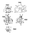
- Fig. 1 there is shown a blank 1 obtained by cutting a sheet of suitable thickness, intended to produce by bending and stamping the collar according to the invention.
- the blank 1 has a generally rectangular shape with rounded ends. It has on one of its sides, a main projection 2 disposed in the middle of said side and two legs 3 and 4 placed symmetrically with respect to the projection 2. The role of the projection 2 and of the legs 3 and 4 will be explained by the after.
- a notch 7 which defines with a slot 8 connecting the orifices 5 and 6 extending parallel to the line joining the centers of these orifices, a tongue 9 whose function will also be explained by the following.
- the slot 8 is offset from the line joining the centers of the orifices 5 and 6 in order to allow the tongue 9 to present this line as an axis of symmetry.
- the tongue 9 has at its free end an enlarged portion 9a.
- the blank 1 which has just been described is produced by cutting and stamping. It is then folded to obtain the collar shown in Figs. 2 to 5.
- a collar is thus obtained comprising two wings 10 and 11 parallel, the tongue 9 constituting an axial immobilization element and in rotation of the collar relative to the part on which it is mounted.
- this part is constituted by the end of a tube 12 in which is formed an axial slot 13 intended to give the tube the elasticity necessary for its tightening and used to receive the tongue 9.
- the slot is terminated by a circular bottom 13a of diameter greater than the width of the slot 13, in which is engaged the enlarged portion 9a of the tongue 9.
- the tongue 9 engaged in the slot 13 ensures the axial immobilization and in rotation of the collar with respect to the tube 12. It follows that the collar can be mounted on the tube and constitute with it, an assembly that the 'can be stored and handled before tightening without risk of loss of the collar.
- the projection 2 is folded so as to constitute a housing 14 for a nut 15, while the rounded central part 16 of the collar joining the wings 10 and 11 forms a passage for a tightening bolt 17 shown in phantom in Fig. 3, intended to cooperate with the nut 15.
- the tube 12 has a transverse cut 12a intended to allow the passage of the bolt 17 which can thus ensure keying between the tube 12 and the part with which it is to be coupled, shown in phantom in FIG. 4.
- the slot 8 joining the two orifices 5 and 6 allows the two parts 16a and 16b to be brought closer to the central part 16 of the collar in order to allow the tightening action of the bolt 17 and of the nut 15.
- the lateral tabs 3 and 4 are also folded up as shown in Fig. 5 to secure the nut 15 in its housing 14. This arrangement is particularly clearly visible in FIG. 5.
- the housing 14 and the folded tabs 3 and 4 constitute at the same time an effective brake for the nut 15.
Description
- La présente invention concerne les colliers d'accouplement et se rapporte plus particulièrement à un collier d'accouplement d'un tube de direction de véhicule automobile sur un arbre.
- D'après FR-A-2 264 211, on connait un collier d'accouplement comportant un corps dans lequel est ménagé un passage pour une pièce à accoupler, des moyens de serrage dudit collier sur la pièce et un organe d'immobilisation du collier par rapport à la pièce, destiné à être engagé dans un évidement de celle-ci.
- On connait en outre d'après DE-C-535696, un collier d'accouplement comportant deux ailes parallèles dans lesquelles sont ménagés des orifices de passage pour une pièce à assembler, lesdites ailes étant reliées entre elles par une partie intermédiaire traversée par une fente réunissant lesdits orifices et formant un passage pour un boulon de serrage, lesdits orifices et ladite fente étant découpés au préalable dans un flan qui est ensuite plié pour obtenir ledit collier.
- L'invention vise à créer un collier d'accouplement qui tout en assurant un serrage efficace, sur pratiquement tout le périmètre des pièces à accoupler, soit réalisable par des opérations simples d'emboutissage et de pliage, et puisse être rendu solidaire de l'une des pièces telle qu'un tube de colonne de direction pendant toutes les opérations telles que stockage et manutention précédant le serrage.
- Elle a donc pour objet un collier d'accouplement comportant un corps dans lequel est ménagé un passage pour une pièce à accoupler, des moyens de serrage dudit collier sur la pièce et un organe d'immobilisation du collier par rapport à la pièce destiné à être engagé dans un évidement de celle-ci, caractérisé en ce que ledit organe d'immobilisation est constitué par une languette latérale venue de matière avec ledit corps et comportant une portion d'extrémité élargie destinée à être engagée dans une portion élargie correspondante d'une fente ménagée dans ladite pièce à accoupler et formant ainsi un organe d'immobilisation axiale et en rotation dudit collier par rapport à ladite pièce.
- L'invention sera mieux comprise à l'aide de la description qui va suivre, donnée uniquement à titre d'exemple et faite en se référant aux dessins annexés, sur lesquels:
- - la Fig. 1 est une vue en plan d'un flan à partir duquel est réalisé le collier suivant l'invention;
- - la Fig. 2 est une vue de dessus du collier terminé monté sur un tube à assembler;
- - la Fig. 3 est une coupe suivant la ligne 3-3 de la Fig. 2;
- - la Fig. 4 est une coupe suivant la ligne 4-4 de la Fig. 2;
- - la Fig. 5 est une vue extérieure en élévation montrant le logement d'écrou du collier suivant l'invention.
- Sur la Fig. 1, on a représenté un flan 1 obtenu par découpe d'une tôle d'épaisseur appropriée, destinée à réaliser par pliage et emboutissage le collier suivant l'invention.
- Le flan 1 présente une forme générale rectangulaire à extrémités arrondies. Il comporte sur l'un de ses côtés, une saillie principale 2 disposée au milieu dudit côté et deux pattes 3 et 4 placées symétriquement par rapport à la saillie 2. Le rôle de la saillie 2 et des pattes 3 et 4 sera expliqué par la suite.
- A proximité des extrémités arrondies du flan 1 sont ménagés des orifices circulaires 5 et 6 destinés à servir de passages pour l'une des pièces à assembler à l'aide du collier suivant l'invention. Dans le périmètre de l'orifice 6 est ménagée une encoche 7 qui définit avec une fente 8 de liaison des orifices 5 et 6 s'étendant parallèlement à la ligne joignant les centres de ces orifices, une languette 9 dont la fonction sera également expliquée par la suite.
- La fente 8 est décalée par rapport à la ligne joignant les centres des orifices 5 et 6 afin de permettre à la languette 9 de présenter cette ligne comme axe de symétrie. La languette 9 présente à son extrémité libre une portion élargie 9a.
- Le flan 1 qui vient d'être décrit est réalisé par découpe et emboutissage. Il est ensuite plié pour obtenir le collier représenté aux Fig. 2 à 5.
- Le pliage est réalisé autour de l'axe de symétrie du flan 1 perpendiculaire à la ligne joignant les centres des orifices 5 et 6. On obtient ainsi un collier comportant deux ailes 10 et 11 parallèles, la languette 9 constituant un élément d'immobilisation axiale et en rotation du collier par rapport à la pièce sur laquelle il est monté.
- Dans l'exemple représenté aux Fig. 2 et 4, cette pièce est constituée par l'extrémité d'un tube 12 dans lequel est ménagée une fente axiale 13 destinée à donner au tube l'élasticité nécessaire à son serrage et utilisée pour recevoir la languette 9. A cet effet, la fente est terminée par un fond circulaire 13a de diamètre supérieur à la largeur de la fente 13, dans lequel est engagée la portion élargie 9a de la languette 9. On voit sur la Fig. 4, que la languette 9 engagée dans la fente 13 assure l'immobilisation axiale et en rotation du collier par rapport au tube 12. Il en résulte que le collier peut être monté sur le tube et constituer avec celui-ci, un ensemble que l'on peut stocker et manipuler avant serrage sans risques de perte du collier.
- Bien entendu, au lieu d'utiliser la fente 13, on peut pour immobiliser le collier sur le tube, prévoir dans le tube un logement pour la patte 9 du collier séparé de ladite fente.
- Ainsi qu'on peut le voir aux Fig. 2 à 5, la saillie 2 est pliée de manière à constituer un logement 14 pour un écrou 15, tandis que la partie centrale arrondie 16 du collier réunissant les ailes 10 et 11 forme un passage pour un boulon de serrage 17 représenté en trait mixte à la Fig. 3, destiné à coopérer avec l'écrou 15. On voit aussi sur la Fig. 3 que le tube 12 présente une découpe transversale 12a destinée à permettre le passage du boulon 17 qui peut ainsi assurer un clavetage entre le tube 12 et la pièce avec laquelle il doit être accouplé, représentée en trait mixte à la Fig. 4.
- La fente 8 réunissant les deux orifices 5 et 6 permet le rapprochement des deux parties 16a et 16b de la partie centrale 16 du collier afin de permettre l'action de serrage du boulon 17 et de l'écrou 15. Les pattes latérales 3 et 4 sont également repliées comme le montre la Fig. 5 pour assurer l'immobilisation de l'écrou 15 dans son logement 14. Cette disposition est particulièrement bien visible à la Fig. 5.
- Le logement 14 et les pattes rabattues 3 et 4 constituent en même temps un frein efficace pour l'écrou 15.
- On voit que le collier qui vient d'être décrit est d'une réalisation particulièrement simple, car il ne nécessite pour sa fabrication que des opérations de découpe d'emboutissage et de pliage.
- En outre, son périmètre de serrage est particulièrement important car il n'est interrompu que par la fente 8 réunissant les orifices 5 et 6 et qui donne au collier, l'élasticité indispensable pour assurer le serrage.
Claims (6)
Applications Claiming Priority (2)
| Application Number | Priority Date | Filing Date | Title |
|---|---|---|---|
| FR8209378A FR2527709A1 (fr) | 1982-05-28 | 1982-05-28 | Collier d'accouplement realise par emboutissage et pliage d'un flan |
| FR8209378 | 1982-05-28 |
Publications (2)
| Publication Number | Publication Date |
|---|---|
| EP0095964A1 EP0095964A1 (fr) | 1983-12-07 |
| EP0095964B1 true EP0095964B1 (fr) | 1986-11-20 |
Family
ID=9274459
Family Applications (1)
| Application Number | Title | Priority Date | Filing Date |
|---|---|---|---|
| EP83401002A Expired EP0095964B1 (fr) | 1982-05-28 | 1983-05-19 | Collier d'accouplement réalisé par emboutissage et pliage d'un flan |
Country Status (6)
| Country | Link |
|---|---|
| US (1) | US4572697A (fr) |
| EP (1) | EP0095964B1 (fr) |
| JP (1) | JPS58217806A (fr) |
| DE (1) | DE3367795D1 (fr) |
| ES (1) | ES272461Y (fr) |
| FR (1) | FR2527709A1 (fr) |
Families Citing this family (4)
| Publication number | Priority date | Publication date | Assignee | Title |
|---|---|---|---|---|
| JPH0442902U (fr) * | 1990-08-14 | 1992-04-13 | ||
| DE19614922A1 (de) * | 1996-04-16 | 1997-10-23 | Opel Adam Ag | Klemmverbindung |
| US6682432B1 (en) * | 2002-09-04 | 2004-01-27 | Kinzou Shinozuka | Multiple shaft diameter flexible coupling system |
| SE527860C2 (sv) * | 2004-10-12 | 2006-06-27 | Volvo Lastvagnar Ab | Klämanordning och stag för fordon som innefattar klämanordningen |
Family Cites Families (7)
| Publication number | Priority date | Publication date | Assignee | Title |
|---|---|---|---|---|
| DE535696C (de) * | 1929-12-06 | 1931-10-14 | Mercedes Bueromaschinen Werke | Klemmbefestigung von Blechstreifen auf Achsen |
| US2039973A (en) * | 1933-12-22 | 1936-05-05 | American Seating Co | Clamp |
| US2122868A (en) * | 1937-06-01 | 1938-07-05 | American Seating Co | Clamp |
| US2451062A (en) * | 1945-12-21 | 1948-10-12 | Thompson Prod Inc | Clamp assembly |
| US2723141A (en) * | 1950-02-25 | 1955-11-08 | Thompson Prod Inc | Clamp locating device |
| FR2264211A1 (en) * | 1974-03-13 | 1975-10-10 | Peugeot & Renault | Joint for motor vehicle exhaust manifold - has collar lug sliding in relatively inclined slots in male and female elements |
| US4016770A (en) * | 1975-11-03 | 1977-04-12 | Gilson Bros. Co. | Pulley assembly |
-
1982
- 1982-05-28 FR FR8209378A patent/FR2527709A1/fr active Granted
-
1983
- 1983-05-19 DE DE8383401002T patent/DE3367795D1/de not_active Expired
- 1983-05-19 EP EP83401002A patent/EP0095964B1/fr not_active Expired
- 1983-05-25 US US06/497,826 patent/US4572697A/en not_active Expired - Fee Related
- 1983-05-26 ES ES1983272461U patent/ES272461Y/es not_active Expired
- 1983-05-28 JP JP58094758A patent/JPS58217806A/ja active Pending
Also Published As
| Publication number | Publication date |
|---|---|
| JPS58217806A (ja) | 1983-12-17 |
| EP0095964A1 (fr) | 1983-12-07 |
| FR2527709A1 (fr) | 1983-12-02 |
| ES272461U (es) | 1983-12-16 |
| US4572697A (en) | 1986-02-25 |
| DE3367795D1 (en) | 1987-01-08 |
| ES272461Y (es) | 1984-07-16 |
| FR2527709B1 (fr) | 1985-03-22 |
Similar Documents
| Publication | Publication Date | Title |
|---|---|---|
| FR2781259A1 (fr) | Cylindre hydraulique | |
| FR2897124A1 (fr) | Dispositif d'immobilisation en rotation d'un ecrou a sertir | |
| EP0095964B1 (fr) | Collier d'accouplement réalisé par emboutissage et pliage d'un flan | |
| FR2691512A1 (fr) | Dispositif de raccord rapide, par encliquetage, d'un ensemble d'organes tubulaires à des embouts. | |
| EP1056969B1 (fr) | Raccord encliquetable pour conduit de fluide | |
| FR2791766A1 (fr) | Equipement encliquetable pour un echangeur de chaleur brase, notamment de vehicule automobile | |
| EP0290698B1 (fr) | Dispositif élastique de centrage et d'accouplement à course morte de deux organes rotatifs | |
| EP1231422B1 (fr) | Procédé pour rendre une vis imperdable, collier de fixation de tuyauteries et utilisation du procédé pour fabriquer les colliers | |
| EP0027765A1 (fr) | Robinet à boule et ses procédés de fabrication | |
| EP1186821A1 (fr) | Raccord de tuyauterie | |
| FR2726075A1 (fr) | Echangeur de chaleur a faisceau de tubes et a collecteur metallique | |
| EP0626533B1 (fr) | Collier de maintien, sur un support, d'un tube ou analogue | |
| EP0481872B1 (fr) | Dispositif de raccordement de deux tuyaux de part et d'autre d'un élément de cloison | |
| FR2799515A1 (fr) | Systeme a rattrapage de jeu pour fixer deux pieces l'une a l'autre au moyen d'un organe de fixation du type a vis | |
| EP0761988B1 (fr) | Dispositif de fixation rapide d'une pièce sur une embase, en particulier d'une électrovanne de machine à laver | |
| FR2741916A1 (fr) | Dispositif de premontage et de retenue d'une vis associee a une piece d'assemblage | |
| FR2764349A1 (fr) | Agrafe d'assemblage de deux elements du type a paroi mince | |
| FR2487933A1 (fr) | Joint de cardan | |
| EP0836685A1 (fr) | Montage de butee de debrayage | |
| EP3844405A1 (fr) | Dispositif de connexion d'éléments tubulaires | |
| FR2674207A1 (fr) | Volant de direction, notamment de vehicule automobile. | |
| FR2594736A3 (fr) | Levier pour dispositifs tendeurs, notamment a leviers a genouillere | |
| FR2879694A1 (fr) | Systeme d'arret de satellite dans un differentiel | |
| EP3486505A1 (fr) | Procédé de fixation d'au moins deux pièces entre elles au moyen d'un ensemble de fixation et ensemble de fixation associé | |
| EP2475532A1 (fr) | Structure tubulaire pour realiser notamment un essieu de train roulant de vehicule automobile |
Legal Events
| Date | Code | Title | Description |
|---|---|---|---|
| PUAI | Public reference made under article 153(3) epc to a published international application that has entered the european phase |
Free format text: ORIGINAL CODE: 0009012 |
|
| AK | Designated contracting states |
Designated state(s): DE GB IT SE |
|
| 17P | Request for examination filed |
Effective date: 19840213 |
|
| ITF | It: translation for a ep patent filed |
Owner name: GUZZI E RAVIZZA S.R.L. |
|
| GRAA | (expected) grant |
Free format text: ORIGINAL CODE: 0009210 |
|
| AK | Designated contracting states |
Kind code of ref document: B1 Designated state(s): DE GB IT SE |
|
| REF | Corresponds to: |
Ref document number: 3367795 Country of ref document: DE Date of ref document: 19870108 |
|
| PLBE | No opposition filed within time limit |
Free format text: ORIGINAL CODE: 0009261 |
|
| STAA | Information on the status of an ep patent application or granted ep patent |
Free format text: STATUS: NO OPPOSITION FILED WITHIN TIME LIMIT |
|
| 26N | No opposition filed | ||
| PGFP | Annual fee paid to national office [announced via postgrant information from national office to epo] |
Ref country code: DE Payment date: 19900425 Year of fee payment: 8 |
|
| PGFP | Annual fee paid to national office [announced via postgrant information from national office to epo] |
Ref country code: GB Payment date: 19900514 Year of fee payment: 8 |
|
| PGFP | Annual fee paid to national office [announced via postgrant information from national office to epo] |
Ref country code: SE Payment date: 19900522 Year of fee payment: 8 |
|
| ITTA | It: last paid annual fee | ||
| PG25 | Lapsed in a contracting state [announced via postgrant information from national office to epo] |
Ref country code: GB Effective date: 19910519 |
|
| PG25 | Lapsed in a contracting state [announced via postgrant information from national office to epo] |
Ref country code: SE Effective date: 19910520 |
|
| GBPC | Gb: european patent ceased through non-payment of renewal fee | ||
| PG25 | Lapsed in a contracting state [announced via postgrant information from national office to epo] |
Ref country code: DE Effective date: 19920303 |
|
| EUG | Se: european patent has lapsed |
Ref document number: 83401002.7 Effective date: 19911209 |