EP0095817B1 - Method of and device for making perforations in a tubular web of plastics foil - Google Patents
Method of and device for making perforations in a tubular web of plastics foil Download PDFInfo
- Publication number
- EP0095817B1 EP0095817B1 EP83200786A EP83200786A EP0095817B1 EP 0095817 B1 EP0095817 B1 EP 0095817B1 EP 83200786 A EP83200786 A EP 83200786A EP 83200786 A EP83200786 A EP 83200786A EP 0095817 B1 EP0095817 B1 EP 0095817B1
- Authority
- EP
- European Patent Office
- Prior art keywords
- web
- gusset
- tubular
- tubular web
- rolls
- Prior art date
- Legal status (The legal status is an assumption and is not a legal conclusion. Google has not performed a legal analysis and makes no representation as to the accuracy of the status listed.)
- Expired
Links
- 239000011888 foil Substances 0.000 title claims abstract description 26
- 238000000034 method Methods 0.000 title claims abstract description 8
- 239000004033 plastic Substances 0.000 title claims abstract description 5
- 229920003023 plastic Polymers 0.000 title claims abstract description 5
- 238000004080 punching Methods 0.000 claims abstract description 21
- 239000000463 material Substances 0.000 claims abstract description 5
- 238000004519 manufacturing process Methods 0.000 claims description 3
- 238000011144 upstream manufacturing Methods 0.000 claims 1
- 239000007788 liquid Substances 0.000 description 1
- 238000012986 modification Methods 0.000 description 1
- 230000004048 modification Effects 0.000 description 1
- 230000035515 penetration Effects 0.000 description 1
- 238000007789 sealing Methods 0.000 description 1
- 238000003860 storage Methods 0.000 description 1
- XLYOFNOQVPJJNP-UHFFFAOYSA-N water Substances O XLYOFNOQVPJJNP-UHFFFAOYSA-N 0.000 description 1
Images


Classifications
-
- B—PERFORMING OPERATIONS; TRANSPORTING
- B26—HAND CUTTING TOOLS; CUTTING; SEVERING
- B26F—PERFORATING; PUNCHING; CUTTING-OUT; STAMPING-OUT; SEVERING BY MEANS OTHER THAN CUTTING
- B26F1/00—Perforating; Punching; Cutting-out; Stamping-out; Apparatus therefor
- B26F1/0015—Perforating; Punching; Cutting-out; Stamping-out; Apparatus therefor specially adapted for perforating tubes
- B26F1/0038—Perforating; Punching; Cutting-out; Stamping-out; Apparatus therefor specially adapted for perforating tubes from the inside
-
- B—PERFORMING OPERATIONS; TRANSPORTING
- B31—MAKING ARTICLES OF PAPER, CARDBOARD OR MATERIAL WORKED IN A MANNER ANALOGOUS TO PAPER; WORKING PAPER, CARDBOARD OR MATERIAL WORKED IN A MANNER ANALOGOUS TO PAPER
- B31B—MAKING CONTAINERS OF PAPER, CARDBOARD OR MATERIAL WORKED IN A MANNER ANALOGOUS TO PAPER
- B31B70/00—Making flexible containers, e.g. envelopes or bags
- B31B70/14—Cutting, e.g. perforating, punching, slitting or trimming
-
- Y—GENERAL TAGGING OF NEW TECHNOLOGICAL DEVELOPMENTS; GENERAL TAGGING OF CROSS-SECTIONAL TECHNOLOGIES SPANNING OVER SEVERAL SECTIONS OF THE IPC; TECHNICAL SUBJECTS COVERED BY FORMER USPC CROSS-REFERENCE ART COLLECTIONS [XRACs] AND DIGESTS
- Y10—TECHNICAL SUBJECTS COVERED BY FORMER USPC
- Y10T—TECHNICAL SUBJECTS COVERED BY FORMER US CLASSIFICATION
- Y10T83/00—Cutting
- Y10T83/04—Processes
- Y10T83/0596—Cutting wall of hollow work
-
- Y—GENERAL TAGGING OF NEW TECHNOLOGICAL DEVELOPMENTS; GENERAL TAGGING OF CROSS-SECTIONAL TECHNOLOGIES SPANNING OVER SEVERAL SECTIONS OF THE IPC; TECHNICAL SUBJECTS COVERED BY FORMER USPC CROSS-REFERENCE ART COLLECTIONS [XRACs] AND DIGESTS
- Y10—TECHNICAL SUBJECTS COVERED BY FORMER USPC
- Y10T—TECHNICAL SUBJECTS COVERED BY FORMER US CLASSIFICATION
- Y10T83/00—Cutting
- Y10T83/384—By tool inside hollow work
-
- Y—GENERAL TAGGING OF NEW TECHNOLOGICAL DEVELOPMENTS; GENERAL TAGGING OF CROSS-SECTIONAL TECHNOLOGIES SPANNING OVER SEVERAL SECTIONS OF THE IPC; TECHNICAL SUBJECTS COVERED BY FORMER USPC CROSS-REFERENCE ART COLLECTIONS [XRACs] AND DIGESTS
- Y10—TECHNICAL SUBJECTS COVERED BY FORMER USPC
- Y10T—TECHNICAL SUBJECTS COVERED BY FORMER US CLASSIFICATION
- Y10T83/00—Cutting
- Y10T83/384—By tool inside hollow work
- Y10T83/395—One tool having only rectilinear motion[s]
- Y10T83/398—Internal tool is an active cutter
Definitions
- the invention relates to a method of and a device for making perforations in the inner gusset portions of a tublar web of plastics foil which is provided with side gussets.
- Perforations in the inner gusset portions serve to remove air and they may be provided such that nevertheless there is no possibility of penetration of liquids, such as for example dew water, as is often formed on the bags in the practice of storage.
- the invention proposes a method wherein the gussets are opened over a distance sufficient to introduce, in the interior thereof, a punching unit, said punching unit being activated by exerting a pressure from the exterior of the tubular web.
- each gusset the two gusset halves are opened simultaneously, in that a punching unit is introduced into the two halves, and that, by exerting the pressure from the exterior, the inner gusset portions of each gusset are both perforated.
- the method as it is proposed according to the invention can be realized with a device which comprises: a separate carrier provided at either one of its ends with rolls and adapted to be introduced into the interior of the tubular web where it is supported and maintained in its place lengthwise of the web, by two sets of rolls which are carried by the machine frame and are situated at the exterior of the tubular web, the carrier being provided with punching units which are so dimensioned and so arranged that they are situated in the gussets, the machine frame outside the tubular web being provided with means to exert a force through the web material, and to activate the punching units.
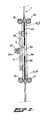
- Fig. 1 apart from the device, there is also diagrammatically represented the tubular web of foil 1, of the type which the invention has an eye on. At the bottom it is visible that side gussets are present in the tube on either side, consisting of inner side gusset portions 2, 2a at one side and inner side gusset portions 3, 3a at the other side, these side gusset portions being situated between outer layers of foil 4, 4a.
- the aim of the invention is to make perforations in the inner side gusset portions 2, 2a; 3, 3a.
- a carrier indicated in its entirety by 5, is introduced into the interior of the tube 1.
- the carrier 5 may consist of two longitudinal elements 6 and 7 which are kept spaced by cross pieces 8 and 9.
- each of the two longitudinal elements 6 and 7 rolls indicated by 10, 11, 12, 13 are provided on either end of each of the two longitudinal elements 6 and 7 rolls indicated by 10, 11, 12, 13 are provided.
- Each of these rolls, in the embodiment represented, is realized as a double roll.
- the axes of a rotation thereof are situated substantially in the plane of carrier 5 in front of the beams 6-9 and the axes of rotation extend parallel to the cross beams 8 and 9.
- the carrier 5 is dimensioned such that the pairs of rolls 10, 11 and 12, 13, respectively, stay within the side gussets, i.e. that the total width thereof is less than the mutual distance of the inner gusset edges 14, 15, respectively.
- the width of the carrier may simply be made adaptable, for example, by changing the length of the cross pieces 8, 9, for example by a shifting connection by means of slits.
- the carrier described is introduced into the interior of the tube when the start of a tube 1 as produced is passed through, by guiding the tube material over the carrier. Then the carrier 5 is kept in place lengthwise of the tubular foil 1, corresponding to the sense in which the tubular foil passes through the machine and indicated by the arrow P, by a pair of lower rolls 16, 17 (compare Fig. 2) and a pair of similar upper rolls 18, 19. The mutual distance of each set of rolls such as 16,17 is less than the diameter of rolls 12, 13 which are provided on the carrier 5 in the interior. As will be understood from Fig.
- the rolls 16-19 are rotatably bearing in the machine frame, indicated by 20.
- the carrier 5 serves to carry punching units or perforating elements. As appears from Fig. 1 four of these perforating units are provided, indicated by 21, 22, 23, 24. Because the structure of all of these units is identical, only unit 21 will be described with reference to Fig. 3.
- the perforating units project in lateral direction with respect to the longitudinal elements 6, 7 of the carrier.
- the unit comprises a fixed supporting arm 25 and a movable arm 26. These two arms are each situated substantially on one side of the longitudinal central plane through the carrier, such that each may come to lie in one side gusset half, with the inner side gusset portions which are to be perforated, such as 2, 2a, lying inbetween the arms 25, 26 as will be further clarified yet.
- the movable arm 26 carries a punch 27 and in fixed arm 25 a rubber base plate 28 is provided. The movable arm 26 is urged away from the fixed arm 25 by a spring which, however, has not been drawn.
- an air cylinder 29 is affixed to the machine frame (the fixation has not been represented in Fig. 3).
- a rubber cap 31 is affixed, which is arranged opposite the movable arm 26. So by operation of the cylinder 29 the cap 31 can simply press against the outer foil layer and thereby exert an impact force on the movable arm 26 by which, by means of punch 27, the desired perforations will be made in the inner side gusset portions such as 2, 2a.
- a shaft 32 On the machine frame 20, substantially midway between the sets of rolls 16, 17 and 18, 19, a shaft 32 is provided.
- Two guide members 33 and 34, respectively, are movable past it. These are supporting vertical beams 35 and 36, respectively, which at their ends carry discs 37, 38, 39, 40. These discs are rotatable with respect to the beams.
- these discs such as 37 are situated substantially in the longitudinal central plane of the device as operable and they are arranged such that they may arrive between the inner side gusset portions 2, 2a to be perforated.
- the guide members such as 33 are preferably under the action of an inwardly directed spring force (springs have not been drawn) so that the discs such as 37 will be urged, by this spring force, against the inner side gusset edge such as 14.
- the discs such as 37 are not situated at the level of the perforating units such as 21, but at a certain distance from these. Each disc such as 37 cooperates with two smaller discs, also rotatable, having the axis of rotation at the same height, but which are provided on the carrier 5 and are therefore situated in the interior of the tubular foil.
- the correct internal arrangement appears best from Fig. 4.
- On a longitudinal carrier beam such as 6 a small block 41 is affixed, carrying the axes of rotation for the set of discs 42, 42a.
- Each of these discs is in shape of a cone having a great apex angle, the axes of rotation of the discs having a corresponding angle with respect to the central longitudinal plane of the device.
- each air cylinder has, in lateral direction, a fixed position with respect to the exterior disc such as 37. Because, as stated, this disc urges against the inner side gusset edge, the air cylinder will also arrive at a fixed distance with respect to said inner side gusset edge, and thereby it arrives within the reach of the movable arm 26 of the punching device.
- the perforating unit can be realized differently, for example maintaining the idea of the movable arm with the punch such as 26, but with the disc such as 37 functioning as counter pressure element.
- This disc might possibly be replaced by a non-rotating element.
- the punching element which is introduced into the interior of the tube, comprise a counter pressure element, the punching then being done from the space situated exteriorly from the tubu- larfoil, but between the inner side gusset portions such as 2, 2a, so from the location where the discs such as 37 or 38 are situated.
- the side gussets will be opened in a somewhat different manner, but also for this, in that case, solutions will lie at hand which can simply be derived from the design and arrangement respectively, of the conical discs such as 42, 42a etc.
- the device as a whole may be mounted on an apparatus for manufacturing a web of bags on a roll, starting from a roll of tubular foil provided with side gussets, always as known in itself.
- perforating is done during the time intervals in which the foil web is at standstill anyhow for making seals.
- the perforating station may then be arranged before the sealing station, at a distance which will depend on the unit length of the bags to be manufactured.
Landscapes
- Forests & Forestry (AREA)
- Engineering & Computer Science (AREA)
- Mechanical Engineering (AREA)
- Life Sciences & Earth Sciences (AREA)
- Making Paper Articles (AREA)
- Shaping Of Tube Ends By Bending Or Straightening (AREA)
- Perforating, Stamping-Out Or Severing By Means Other Than Cutting (AREA)
- Details Of Cutting Devices (AREA)
- Laminated Bodies (AREA)
- Dowels (AREA)
- Agricultural Chemicals And Associated Chemicals (AREA)
- Beans For Foods Or Fodder (AREA)
- Solid-Sorbent Or Filter-Aiding Compositions (AREA)
- Heating, Cooling, Or Curing Plastics Or The Like In General (AREA)
Priority Applications (1)
| Application Number | Priority Date | Filing Date | Title |
|---|---|---|---|
| AT83200786T ATE20582T1 (de) | 1982-06-02 | 1983-06-01 | Verfahren und vorrichtung zum durchlochen einer schlauchbahn aus plastikfolie. |
Applications Claiming Priority (2)
| Application Number | Priority Date | Filing Date | Title |
|---|---|---|---|
| NL8202231A NL8202231A (nl) | 1982-06-02 | 1982-06-02 | Werkwijze en inrichting voor het aanbrengen van perforaties in een buisvormige kunststoffoliebaan. |
| NL8202231 | 1982-06-02 |
Publications (2)
| Publication Number | Publication Date |
|---|---|
| EP0095817A1 EP0095817A1 (en) | 1983-12-07 |
| EP0095817B1 true EP0095817B1 (en) | 1986-07-02 |
Family
ID=19839811
Family Applications (1)
| Application Number | Title | Priority Date | Filing Date |
|---|---|---|---|
| EP83200786A Expired EP0095817B1 (en) | 1982-06-02 | 1983-06-01 | Method of and device for making perforations in a tubular web of plastics foil |
Country Status (10)
| Country | Link |
|---|---|
| US (1) | US4517868A (da) |
| EP (1) | EP0095817B1 (da) |
| JP (1) | JPS5916715A (da) |
| AT (1) | ATE20582T1 (da) |
| DE (1) | DE3364373D1 (da) |
| DK (1) | DK158076C (da) |
| FI (1) | FI79054C (da) |
| NL (1) | NL8202231A (da) |
| NO (1) | NO157490C (da) |
| ZA (1) | ZA833979B (da) |
Families Citing this family (4)
| Publication number | Priority date | Publication date | Assignee | Title |
|---|---|---|---|---|
| DE19605021A1 (de) * | 1996-01-31 | 1997-08-07 | Mannesmann Ag | Maschine zum Trennen von Rohren |
| IT1296567B1 (it) * | 1997-11-28 | 1999-07-09 | Bl Macchine Automatiche | Dispositivo per realizzare i soffietti laterali durante lo svolgimento dalla bobina di alimentazione di una manica tubolare continua di |
| SE514109C2 (sv) | 1999-05-04 | 2001-01-08 | Nederman Philip & Co Ab | Anordning vid skenor för avgasutsugningsanordningar |
| CN112008801A (zh) * | 2020-08-19 | 2020-12-01 | 商兆惠 | 一种hdpe管打孔方法 |
Family Cites Families (16)
| Publication number | Priority date | Publication date | Assignee | Title |
|---|---|---|---|---|
| US1048348A (en) * | 1911-05-15 | 1912-12-24 | Benjamin J Rowley | Mandrel for tinners. |
| US1588200A (en) * | 1925-03-12 | 1926-06-08 | Randomtex Dyeing Machine Corp | Perforating device for cones |
| BE547189A (da) * | 1955-04-22 | 1900-01-01 | ||
| US3288006A (en) * | 1963-08-14 | 1966-11-29 | Continental Can Co | Magnetic impulse scoring and/or cutoff of electrically conductive sections |
| FR1376090A (fr) * | 1963-11-25 | 1964-10-23 | Jean Mahieu Ets | Installation pour la fabrication de sacs à valve, procédé de fabrication de ces sacs et sacs obtenus |
| US3291007A (en) * | 1964-02-28 | 1966-12-13 | Olin Mathieson | Anti-friction former device |
| US3259003A (en) * | 1964-06-26 | 1966-07-05 | American Radiator & Standard | Method and apparatus for forming openings in tubular members |
| DE1238194B (de) * | 1965-03-06 | 1967-04-06 | Frieseke & Hoepfner Gmbh | Vorrichtung zum Schlitzen von Kunststoffrohren, insbesondere fuer Draenagezwecke |
| FR1459894A (fr) * | 1965-08-23 | 1966-06-17 | Windmoeller & Hoelscher | Procédé de fabrication de sacs à provision et dispositif pour la mise en oeuvre de ce procédé |
| US3487668A (en) * | 1966-07-12 | 1970-01-06 | Western Electric Co | Shaping and forming articles |
| DE1561462B1 (de) * | 1967-02-13 | 1970-11-12 | Windmoeller & Hoelscher | Vorrichtung zum Bearbeiten,beispielsweise Stanzen,Schneiden oder Durchbohren,von kontinuierlich bewegten Werkstoffbahnen in Beutel- und Sackmaschinen |
| US3720141A (en) * | 1970-04-08 | 1973-03-13 | Fmc Corp | Apparatus for making thermoplastic handle bags |
| BE806799A (fr) * | 1973-10-31 | 1974-02-15 | Promopack S A | Procede de fabrication de sachets d'exposition destines a la presentation de produits |
| JPS50144191A (da) * | 1974-05-09 | 1975-11-19 | ||
| US3995518A (en) * | 1975-08-28 | 1976-12-07 | Spiroff Carl M | Means and methods for punching holes in catheters |
| EP0002326A1 (en) * | 1977-11-23 | 1979-06-13 | Harwell Packaging Limited | Valve sack and method of making it |
-
1982
- 1982-06-02 NL NL8202231A patent/NL8202231A/nl not_active Application Discontinuation
-
1983
- 1983-05-31 NO NO831936A patent/NO157490C/no unknown
- 1983-06-01 AT AT83200786T patent/ATE20582T1/de not_active IP Right Cessation
- 1983-06-01 DK DK249183A patent/DK158076C/da active
- 1983-06-01 JP JP58095902A patent/JPS5916715A/ja active Granted
- 1983-06-01 EP EP83200786A patent/EP0095817B1/en not_active Expired
- 1983-06-01 DE DE8383200786T patent/DE3364373D1/de not_active Expired
- 1983-06-02 ZA ZA833979A patent/ZA833979B/xx unknown
- 1983-06-02 US US06/500,422 patent/US4517868A/en not_active Expired - Fee Related
- 1983-06-02 FI FI831986A patent/FI79054C/fi not_active IP Right Cessation
Also Published As
| Publication number | Publication date |
|---|---|
| FI79054C (fi) | 1989-11-10 |
| ZA833979B (en) | 1984-07-25 |
| DE3364373D1 (en) | 1986-08-07 |
| NO157490B (no) | 1987-12-21 |
| DK249183A (da) | 1983-12-03 |
| ATE20582T1 (de) | 1986-07-15 |
| JPS5916715A (ja) | 1984-01-27 |
| DK158076B (da) | 1990-03-26 |
| FI79054B (fi) | 1989-07-31 |
| FI831986L (fi) | 1983-12-03 |
| NL8202231A (nl) | 1984-01-02 |
| DK158076C (da) | 1990-09-17 |
| JPH0321320B2 (da) | 1991-03-22 |
| DK249183D0 (da) | 1983-06-01 |
| EP0095817A1 (en) | 1983-12-07 |
| FI831986A0 (fi) | 1983-06-02 |
| US4517868A (en) | 1985-05-21 |
| NO831936L (no) | 1983-12-05 |
| NO157490C (no) | 1988-04-06 |
Similar Documents
| Publication | Publication Date | Title |
|---|---|---|
| US3618286A (en) | Bag filling sealing and separating system | |
| EP0400577B1 (en) | Process for processing easy-opening on bag and apparatus embodying same | |
| AU3138699A (en) | A method and a system for filling goods in bags from a coherent series of bag members | |
| US3751875A (en) | Apparatus for filling, sealing and dispensing bags | |
| US3763627A (en) | Article packaging system | |
| EP0095817A1 (en) | Method of and device for making perforations in a tubular web of plastics foil | |
| US4167131A (en) | Skip perforator | |
| US6015373A (en) | Method for wicket-top converting of a cross-laminated synthetic resin fiber mesh bag | |
| EP0007443A1 (en) | Bag folding machine | |
| US6080093A (en) | Apparatus for wicket-top converting of a cross-laminated synthetic resin fiber mesh bag | |
| US5957823A (en) | Folding mechanism for a bag knitting apparatus | |
| US3721375A (en) | Web feed mechanism for wrapping machines | |
| JPS6030162Y2 (ja) | 包装体の紙袋を剥脱する装置 | |
| EP0134711B1 (en) | Twin wicketing bag machine | |
| MXPA06012114A (es) | Maquina de bolsas verticales. | |
| JPH03212308A (ja) | 製品包装用装置 | |
| JPH0326087Y2 (da) | ||
| IT202100022598A1 (it) | Un dispositivo a lame ruotanti, una macchina comprendente detto dispositivo, e metodo | |
| JPH01184125A (ja) | 合成樹脂フィルム孔開け装置 | |
| JPS5836514Y2 (ja) | ポリチュ−ブ原反のミシン目形成装置 | |
| JP3816468B2 (ja) | フィルム製包装袋の製造方法及びその製造装置 | |
| WO1996003272A1 (en) | Method and apparatus for manufacturing stand-up plastic bags | |
| US3084581A (en) | Machine for making garment bags and the like | |
| US535591A (en) | Paper-bag machine | |
| JPS6365583B2 (da) |
Legal Events
| Date | Code | Title | Description |
|---|---|---|---|
| PUAI | Public reference made under article 153(3) epc to a published international application that has entered the european phase |
Free format text: ORIGINAL CODE: 0009012 |
|
| AK | Designated contracting states |
Designated state(s): AT BE CH DE FR GB IT LI LU NL SE |
|
| 17P | Request for examination filed |
Effective date: 19840328 |
|
| GRAA | (expected) grant |
Free format text: ORIGINAL CODE: 0009210 |
|
| ITF | It: translation for a ep patent filed | ||
| AK | Designated contracting states |
Kind code of ref document: B1 Designated state(s): AT BE CH DE FR GB IT LI LU NL SE |
|
| REF | Corresponds to: |
Ref document number: 20582 Country of ref document: AT Date of ref document: 19860715 Kind code of ref document: T |
|
| REF | Corresponds to: |
Ref document number: 3364373 Country of ref document: DE Date of ref document: 19860807 |
|
| ET | Fr: translation filed | ||
| PLBE | No opposition filed within time limit |
Free format text: ORIGINAL CODE: 0009261 |
|
| STAA | Information on the status of an ep patent application or granted ep patent |
Free format text: STATUS: NO OPPOSITION FILED WITHIN TIME LIMIT |
|
| 26N | No opposition filed | ||
| PGFP | Annual fee paid to national office [announced via postgrant information from national office to epo] |
Ref country code: LU Payment date: 19910430 Year of fee payment: 9 |
|
| PGFP | Annual fee paid to national office [announced via postgrant information from national office to epo] |
Ref country code: SE Payment date: 19910503 Year of fee payment: 9 |
|
| PGFP | Annual fee paid to national office [announced via postgrant information from national office to epo] |
Ref country code: CH Payment date: 19910506 Year of fee payment: 9 |
|
| PGFP | Annual fee paid to national office [announced via postgrant information from national office to epo] |
Ref country code: GB Payment date: 19910508 Year of fee payment: 9 |
|
| PGFP | Annual fee paid to national office [announced via postgrant information from national office to epo] |
Ref country code: AT Payment date: 19910515 Year of fee payment: 9 |
|
| PGFP | Annual fee paid to national office [announced via postgrant information from national office to epo] |
Ref country code: FR Payment date: 19910529 Year of fee payment: 9 Ref country code: DE Payment date: 19910529 Year of fee payment: 9 |
|
| PGFP | Annual fee paid to national office [announced via postgrant information from national office to epo] |
Ref country code: BE Payment date: 19910531 Year of fee payment: 9 |
|
| ITTA | It: last paid annual fee | ||
| PGFP | Annual fee paid to national office [announced via postgrant information from national office to epo] |
Ref country code: NL Payment date: 19910630 Year of fee payment: 9 |
|
| EPTA | Lu: last paid annual fee | ||
| PG25 | Lapsed in a contracting state [announced via postgrant information from national office to epo] |
Ref country code: LU Free format text: LAPSE BECAUSE OF NON-PAYMENT OF DUE FEES Effective date: 19920601 Ref country code: GB Effective date: 19920601 Ref country code: AT Effective date: 19920601 |
|
| PG25 | Lapsed in a contracting state [announced via postgrant information from national office to epo] |
Ref country code: SE Effective date: 19920602 |
|
| PG25 | Lapsed in a contracting state [announced via postgrant information from national office to epo] |
Ref country code: LI Effective date: 19920630 Ref country code: CH Effective date: 19920630 Ref country code: BE Effective date: 19920630 |
|
| BERE | Be: lapsed |
Owner name: WAVIN B.V. Effective date: 19920630 |
|
| PG25 | Lapsed in a contracting state [announced via postgrant information from national office to epo] |
Ref country code: NL Effective date: 19930101 |
|
| GBPC | Gb: european patent ceased through non-payment of renewal fee |
Effective date: 19920601 |
|
| NLV4 | Nl: lapsed or anulled due to non-payment of the annual fee | ||
| PG25 | Lapsed in a contracting state [announced via postgrant information from national office to epo] |
Ref country code: FR Effective date: 19930226 |
|
| REG | Reference to a national code |
Ref country code: CH Ref legal event code: PL |
|
| PG25 | Lapsed in a contracting state [announced via postgrant information from national office to epo] |
Ref country code: DE Effective date: 19930302 |
|
| REG | Reference to a national code |
Ref country code: FR Ref legal event code: ST |
|
| EUG | Se: european patent has lapsed |
Ref document number: 83200786.8 Effective date: 19930109 |