EP0094966B1 - Detektor für den wärmsten punkt mittels siedepunktsfeststellung - Google Patents
Detektor für den wärmsten punkt mittels siedepunktsfeststellung Download PDFInfo
- Publication number
- EP0094966B1 EP0094966B1 EP83900236A EP83900236A EP0094966B1 EP 0094966 B1 EP0094966 B1 EP 0094966B1 EP 83900236 A EP83900236 A EP 83900236A EP 83900236 A EP83900236 A EP 83900236A EP 0094966 B1 EP0094966 B1 EP 0094966B1
- Authority
- EP
- European Patent Office
- Prior art keywords
- detector
- liquid
- boiling
- pressure
- container
- Prior art date
- Legal status (The legal status is an assumption and is not a legal conclusion. Google has not performed a legal analysis and makes no representation as to the accuracy of the status listed.)
- Expired
Links
- 238000009835 boiling Methods 0.000 claims abstract description 61
- 239000007788 liquid Substances 0.000 claims abstract description 56
- 238000000034 method Methods 0.000 claims description 26
- NBVXSUQYWXRMNV-UHFFFAOYSA-N fluoromethane Chemical compound FC NBVXSUQYWXRMNV-UHFFFAOYSA-N 0.000 claims description 21
- 230000005587 bubbling Effects 0.000 claims description 15
- 238000001514 detection method Methods 0.000 claims description 12
- 230000015572 biosynthetic process Effects 0.000 claims description 3
- 238000011049 filling Methods 0.000 claims description 3
- 230000008878 coupling Effects 0.000 claims 1
- 238000010168 coupling process Methods 0.000 claims 1
- 238000005859 coupling reaction Methods 0.000 claims 1
- 239000004065 semiconductor Substances 0.000 abstract description 5
- 230000003247 decreasing effect Effects 0.000 abstract description 2
- 239000012530 fluid Substances 0.000 description 28
- 238000012360 testing method Methods 0.000 description 18
- 238000010438 heat treatment Methods 0.000 description 14
- 239000002826 coolant Substances 0.000 description 13
- 238000006073 displacement reaction Methods 0.000 description 13
- 238000010276 construction Methods 0.000 description 9
- 229910052782 aluminium Inorganic materials 0.000 description 8
- XAGFODPZIPBFFR-UHFFFAOYSA-N aluminium Chemical compound [Al] XAGFODPZIPBFFR-UHFFFAOYSA-N 0.000 description 8
- 238000009833 condensation Methods 0.000 description 7
- 230000005494 condensation Effects 0.000 description 7
- 238000000576 coating method Methods 0.000 description 6
- 238000001816 cooling Methods 0.000 description 6
- 229910001220 stainless steel Inorganic materials 0.000 description 6
- 239000010935 stainless steel Substances 0.000 description 6
- OAICVXFJPJFONN-UHFFFAOYSA-N Phosphorus Chemical compound [P] OAICVXFJPJFONN-UHFFFAOYSA-N 0.000 description 5
- 238000012546 transfer Methods 0.000 description 5
- 241001156002 Anthonomus pomorum Species 0.000 description 4
- 239000011248 coating agent Substances 0.000 description 4
- 239000004020 conductor Substances 0.000 description 3
- 230000000694 effects Effects 0.000 description 3
- 238000005259 measurement Methods 0.000 description 3
- 230000005855 radiation Effects 0.000 description 3
- 230000003213 activating effect Effects 0.000 description 2
- 238000006243 chemical reaction Methods 0.000 description 2
- 238000012937 correction Methods 0.000 description 2
- 239000007789 gas Substances 0.000 description 2
- WMIYKQLTONQJES-UHFFFAOYSA-N hexafluoroethane Chemical compound FC(F)(F)C(F)(F)F WMIYKQLTONQJES-UHFFFAOYSA-N 0.000 description 2
- 239000000463 material Substances 0.000 description 2
- 229910052751 metal Inorganic materials 0.000 description 2
- 239000002184 metal Substances 0.000 description 2
- 238000002156 mixing Methods 0.000 description 2
- 229920001200 poly(ethylene-vinyl acetate) Polymers 0.000 description 2
- 229920006395 saturated elastomer Polymers 0.000 description 2
- 230000007704 transition Effects 0.000 description 2
- IJGRMHOSHXDMSA-UHFFFAOYSA-N Atomic nitrogen Chemical compound N#N IJGRMHOSHXDMSA-UHFFFAOYSA-N 0.000 description 1
- VYPSYNLAJGMNEJ-UHFFFAOYSA-N Silicium dioxide Chemical compound O=[Si]=O VYPSYNLAJGMNEJ-UHFFFAOYSA-N 0.000 description 1
- 229910000831 Steel Inorganic materials 0.000 description 1
- 238000010420 art technique Methods 0.000 description 1
- 239000003990 capacitor Substances 0.000 description 1
- 230000008859 change Effects 0.000 description 1
- 230000000052 comparative effect Effects 0.000 description 1
- 150000001875 compounds Chemical class 0.000 description 1
- 239000000356 contaminant Substances 0.000 description 1
- 230000008602 contraction Effects 0.000 description 1
- 230000007547 defect Effects 0.000 description 1
- 230000001419 dependent effect Effects 0.000 description 1
- 238000013461 design Methods 0.000 description 1
- 238000010586 diagram Methods 0.000 description 1
- ATUOYWHBWRKTHZ-UHFFFAOYSA-N dimethylmethane Natural products CCC ATUOYWHBWRKTHZ-UHFFFAOYSA-N 0.000 description 1
- 229910001873 dinitrogen Inorganic materials 0.000 description 1
- 238000009826 distribution Methods 0.000 description 1
- 238000005530 etching Methods 0.000 description 1
- 239000011521 glass Substances 0.000 description 1
- 229930195733 hydrocarbon Natural products 0.000 description 1
- 150000002430 hydrocarbons Chemical class 0.000 description 1
- 239000005457 ice water Substances 0.000 description 1
- 238000007654 immersion Methods 0.000 description 1
- 239000004922 lacquer Substances 0.000 description 1
- 231100000053 low toxicity Toxicity 0.000 description 1
- 238000004519 manufacturing process Methods 0.000 description 1
- 230000007246 mechanism Effects 0.000 description 1
- 238000001465 metallisation Methods 0.000 description 1
- 238000004377 microelectronic Methods 0.000 description 1
- 238000012986 modification Methods 0.000 description 1
- 230000004048 modification Effects 0.000 description 1
- 238000009828 non-uniform distribution Methods 0.000 description 1
- 230000003287 optical effect Effects 0.000 description 1
- 238000004806 packaging method and process Methods 0.000 description 1
- 230000002093 peripheral effect Effects 0.000 description 1
- 238000003825 pressing Methods 0.000 description 1
- 230000008569 process Effects 0.000 description 1
- 239000001294 propane Substances 0.000 description 1
- 238000005057 refrigeration Methods 0.000 description 1
- 230000004044 response Effects 0.000 description 1
- 230000000630 rising effect Effects 0.000 description 1
- 229910052710 silicon Inorganic materials 0.000 description 1
- 239000010703 silicon Substances 0.000 description 1
- 229910052814 silicon oxide Inorganic materials 0.000 description 1
- 229910000679 solder Inorganic materials 0.000 description 1
- 230000003595 spectral effect Effects 0.000 description 1
- 239000010959 steel Substances 0.000 description 1
- 238000013022 venting Methods 0.000 description 1
- 230000004304 visual acuity Effects 0.000 description 1
- 238000010618 wire wrap Methods 0.000 description 1
Images


Classifications
-
- G—PHYSICS
- G01—MEASURING; TESTING
- G01K—MEASURING TEMPERATURE; MEASURING QUANTITY OF HEAT; THERMALLY-SENSITIVE ELEMENTS NOT OTHERWISE PROVIDED FOR
- G01K13/00—Thermometers specially adapted for specific purposes
-
- G—PHYSICS
- G01—MEASURING; TESTING
- G01N—INVESTIGATING OR ANALYSING MATERIALS BY DETERMINING THEIR CHEMICAL OR PHYSICAL PROPERTIES
- G01N25/00—Investigating or analyzing materials by the use of thermal means
- G01N25/02—Investigating or analyzing materials by the use of thermal means by investigating changes of state or changes of phase; by investigating sintering
- G01N25/08—Investigating or analyzing materials by the use of thermal means by investigating changes of state or changes of phase; by investigating sintering of boiling point
- G01N25/085—Investigating nucleation
-
- G—PHYSICS
- G01—MEASURING; TESTING
- G01N—INVESTIGATING OR ANALYSING MATERIALS BY DETERMINING THEIR CHEMICAL OR PHYSICAL PROPERTIES
- G01N25/00—Investigating or analyzing materials by the use of thermal means
- G01N25/72—Investigating presence of flaws
Definitions
- This invention relates to an ebulliometric method for detecting hot spots on an electronic device, and to a detector for use in carrying out the method.
- Operating microelectronic devices may have highly nonuniform temperature distributions resulting mainly from ohmic heating.
- the nonuniform distributions may result in localized hot spots which induce early failures of the devices.
- localized heating may result from defects in metallizing, such as excessive metal etching or poor plate through connections, which in turn cause the current carrying area to be insufficient under load. Poor heat sink design and inadequate solder connections may also result in localized heating of printed circuit boards. Localized heating causes hot spots and related failure problems.
- Integrated circuits are subject to troubles similar to those which may afflict printed circuit boards.
- One prior art method of locating hot spots is the scanning infrared microscope.
- This device detects the infrared radiation emitted from electronic circuits under test.
- Infrared detection systems are complex, expensive, and difficult to use. Further, they are not suitable for use with large scale integrated circuits because of the inherent resolving power limitations of infrared systems.
- An infrared detection system can only resolve emission regions having sizes of the order of the wave length of the detected radiation, or greater. For example, a modern high quality infrared microscope, discussed in Barnes Engineering Co. Bulletin 12-910C, having a spectral response of about 1.8 to 5.5 microns can resolve emitting regions greater than about 7.6 microns diameter.
- Present-day semiconductor devices very often have structures which are less than one micron in size; these structures cannot be resolved under an infrared microscope.
- Infrared detection of hot spots is also not conducive to the determination of absolute hot spot temperatures because of the dependence of the infrared radiation upon the emissivity of the radiating region.
- a semiconductor device has a number of materials with different emissivities such as bare silicon, silicon oxide, metallized conductors, and passivating glass.
- Present practice is to coat a device with black lacquer in order to obtain uniform emissivity.
- the coating obscures the view of the precise structure of the device under test.
- the coating being a good radiator, alters the thermal characteristics of the device, thereby making quantitative interpretation of measurements difficult.
- metallized conductors may be particularly troublesome because the conductors act as mirrors and give false indications of hot spots by generating reflections from nearby light sources.
- Brenner describes a technique for the determination of hot spot temperatures by coating a transistor chip with a temperature-sensitive phosphor.
- the phosphor's fluorescence when irradiated by ultraviolet light of suitable intensity is strongly temperature-dependent.
- Brenner mounted the coated chips on a temperature-controlled heat sink and applied various voltages to the chip. The fluorescent pattern was photographed through an enlarging lens and the film analyzed with a microdensitometer to extract temperature data.
- thermoelectric element which is cooled to a temperature below the condensation temperature of nitrogen gas saturated with a fluorocarbon liquid. The saturated gas is blown across the device until the fluorocarbon forms a condensation layer on the device surface. Power is then applied to the device until hot spots exhibit themselves as breaks in the condensation layer.
- the surface temperature of a hot spot at any given power input is determined by cooling the thermoelectric element to a second temperature at which condensation on the hot spot recurs. It is assumed that the difference between the temperatures of the hot spot and thermoelectric device is essentially independent of the thermoelectric device temperature. The hot spot temperature at any ambient temperature is therefore assumed to be the temperature difference between the ambient and second thermoelectric element temperatures plus the condensation temperature of the fluorocarbon liquid. Observations of the breaks in the condensation layer and the subsequent recondensation are made through a microscope.
- Hot spots manifest themselves as boiling sites.
- the technique has been used to detect hot spots on printed circuit, multi-layered and wire wrap boards.
- the technique has not previously given good results for integrated circuits because the bubbles emitted from hot spots disturb the fluid surface, making it difficult to see individual boiling sites and otherwise obscuring the view of the boiling sites.
- the technique is in any event limited to the detection of hot spots having temperatures above the boiling point of the particular liquid used.
- the boiling technique has not been applied to hot spot temperature determination.
- an ebulliometric method for detecting hot spots on a powered electronic device comprising the steps of submerging a powered electronic device in ebulliometric liquid, and observing boiling sites on the device by observing bubbling therefrom, characterised by the steps of producing such pressure in the liquid as to produce boiling from the device, and increasing the pressure until the boiling ceases.
- the method is carried out so as to avoid spurious boiling point determinations resulting from superheating of the liquid before nucleate boiling occurs, as discussed, e.g. in Van Stralen and Cole, Boiling Phenomena, Vol. 1, p. 71, (McGraw Hill, 1979).
- Liquid superheating may occur when the temperature of a liquid at substantially fixed pressure is increased from a temperature below the boiling point. It has been observed that the liquid may reach a temperature many degrees above its boiling point before the onset of nucleate boiling. When nucleate boiling begins and the liquid pressure is subsequently increased, the size of the bubbles associated with boiling is observed to decrease until bubble formation stops. The pressure and temperature at which bubble formation just terminates is substantially the boiling point of the liquid.
- an ebulliometric hot spot detector for detecting hot spots on an electronic device by a method according the invention, comprising container means for containing an ebulliometric liquid and a powered electronic device, with the device supported submerged in the liquid, power means for applying power to the device, detector means for detecting bubbling of the liquid from the surface of the device, and means for detecting the location of the sites of the bubbling, characterised by pressurizing means for establishing and varying pressure in the liquid in the container means, the detector means including means for detecting the onset and termination of bubbling as the pressure is varied, and output means responsive to the pressure for generating and displaying a signal indicative of a parameter of the liquid at the time of termination of bubbling.
- the container means is filled with a clean fluid having a known relationship between boiling temperature and pressure.
- a device to be tested, connected for operation, is immersed in the fluid and the pressure of the fluid reduced until boiling is detected.
- the pressure is then increased, causing the size of the vapor bubbles involved in the boiling process to decrease.
- the boiling site or sites are determined with precision.
- the pressure is then increased, and the pressure at which boiling terminates is noted.
- the pressure at which boiling just terminates may be referred to as the ebulliometric pressure for the fluid at the temperature of the hottest hot spot on the device under test.
- thermocouple hot spot device which in a specific construction has been named a "whirligig", is heated while the pressure in the container is held constant at the previously determined ebulliometric pressure.
- the temperature of the whirligig hot spot is slowly decreased under microprocessor control until the highest temperature at which boiling stops is observed.
- the observed temperature may be referred to as the ebulliometric temperature corresponding to the pressure in the container.
- the temperature of the hottest hot spot on the device is thereby determined.
- Conversion tables available to the microprocessor then permit the microprocessor to provide the hot spot temperature in air corresponding to the hot spot temperature determined in the fluid.
- the whirligig may be operated in air at the same value of power input as at the cessation of boiling in liquid to approximate the hot spot temperature in air.
- Liquids usable for hot spot detection with electronic devices such as semiconductor devices and printed circuits which may be referred to as "ebulliometric" liquids, must have low boiling points and be electrically nonconductive. Additional desirable characteristics are low toxicity and substantial nonflammability for ease and safety of handling, and a low dielectric constant to provide minimal interference with the electrical operation of a device under test resulting from the capacitance between the device and the testing vessel. All of the desirable properties are found in fluorocarbons such as the perfluorinated hydrocarbons hexafluoroethane and octofluoro- propane. The following "R” compounds, which may be purchased under the Freon and Genetron trademarks, have been found useful for application to hot spot detection: R-13, R-13B1, R-114, R-500 and R-502.
- a positive displacement bellows pump can be used to vary pressures ranging from pressures below to substantially in excess of atmospheric pressure without contaminating the liquid.
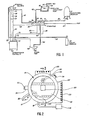
- a specific construction of a preferred embodiment of a hot spot detector comprises a bubble cauldron 10 with an optically clear window 12.
- the bubble cauldron 10 is connected to a fluorocarbon reservoir 14 through a multivalve manifold 16.
- a fluorocarbon.transfer line 18 connects the manifold 16 to the bubble cauldron 10.
- a fluorocarbon fill line 10 connects the fluorocarbon reservoir 14 to the manifold 16.
- a coolant fluid transfer line 22 feeds through a microprocessor controlled coolant solenoid valve 24 to a coolant reservoir 26.
- the coolant fluid may comprise liquid CO 2 ,
- a microprocessor/controller 30 is connected to the coolant solenoid valve 24 by a coolant control bus 32.
- the microprocessor/controller 30 is also connected to the cauldron 10 by thermocouple leads 34, heating coil leads 36, and sensing and control leads 38.
- a roughing vacuum pump 50 is activated by control leads 52 from the microprocessor/controller 30.
- the vacuum pump 50 is connected to the manifold 16 by a vacuum line 54.
- a bellows displacement pump 60 is connected to the manifold 16 by a pressure line 62.
- the displacement pump 60 is controlled by a remote switch 64 connected to a displacement pump motor 65 by a remote lead 66.
- the multivalve manifold 16 includes four ports having solenoid controlled valves.
- a first port 70 vents to the atmosphere.
- a second port 72 connects to the vacuum line 54.
- a third port 74 connects to the fluorocarbon fill line 20.
- the fourth port 76 connects to the pressure line 62.
- a solenoid bus 78 from the microprocessor/controller 30 includes lines 80, 82, 84, and 86 controlling, respectively, the solenoids at the ports 70, 72, 74 and 76.
- Lines 88 include transducer lines connecting a pressure transducer 89 within the manifold 16 to the microprocessor/controller 30 by way of a sensing bus 90.
- a vent 92 from the first port 70 provides for venting the manifold 16 to the atmosphere.
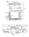
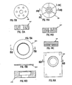
- Figure 2 shows a plan view of the bubble cauldron 10 with a device 100 being tested for hot spots shown in place. The view shown is through the optically clear window 12.
- Figure 3 shows an exploded cross-sectional view of the bubble cauldron 10.
- the bubble cauldron 10 comprises a main chamber 102, which may be formed by an aluminum drum 103 about 4.83 cm height and 9.2 cm diameter, open at its top end and enclosing a cylindrical chamber about 3.56 cm high and 6.35 cm in diameter.
- the drum 103 is made of conducting metal in a preferred embodiment for ease of heating and cooling of the chamber's contents.
- the drum 103 and in fact the entire structure to be described, must be sufficiently strong to withstand pressures to be applied to the contents of the bubble cauldron 10.
- the drum 103 may be made to rest upon a separate base 150 in which heating coils 104 may be embedded with heater current leads 36 projecting from the side of the base 150 and connecting to an external current source in the microprocessor/controller 30.
- cooling coils 106 may be embedded in the base 150 and connected to the coolant fluid transfer line 22 and to a coolant gas vent 27.
- a thermocouple junction 108 is provided in the interior of the main chamber 102 with means for passing the thermocouple leads 34 through the chamber wall while preserving the pressure integrity of the wall.
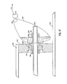
- a printed circuit board 110 adapted for use with the bubble cauldron 10 fits snugly over the top of the main chamber 102. Apertures are provided in the circuit board to provide for the free flow of liquid from the main chamber into the region above the circuit board. Means such as socket connectors are provided on the upper face of the printed circuit board for rapid connection of a device 100 which is indicated diagrammatically in Figure 3.
- An annular seal 112 mounts above the printed circuit board 110 so that the printed circuit board 110 fits between the annular seal 112 and the top of the drum 103. The annular seal 112 is secured to the drum 103 by screws 114 which pass through the printed circuit board 110 into the top of the wall of the drum 103.
- a top lid 115 containing the optically clear window 12 fits snugly over the annular seal 112 so that the optically clear window 12 fits directly above the device 100 under test, the optically clear window being substantially parallel to the printed circuit board 110.
- the device 100 under test is substantially centered with respect to the circular perimeter of the main chamber 102 and also with respect to the optically clear window 12.
- the underside 117 of the top lid 115 may be made attachable to the drum 103 by rapid attachment means such as a bayonet type fitting.
- a microscope or other viewing means 116 and a light source 118 may be placed directly above the optically clear window 12 for viewing.
- One variation of the specific construction described herein includes means 121 for applying pressure pulses to the fluid in the bubble cauldron 10 during viewing as indicated schematically in Figure 3.
- Mixing means for insuring thermal mixing may also be associated with means 121.
- the pressure pulses may be used to move convection plumes obscuring the view of the device 100 under test through the viewing means 116.
- a part of the printed circuit board 110 projects beyond the periphery of the drum 103 and provides ribbon connectors 122 for making electronic connections to the printed circuit board 110 and thence to the device 100 under test.
- Means are also provided for connecting the fluid transfer line 18 to the main chamber 102 for filling the bubble cauldron 10 with fluorocarbon fluid as is indicated in Figure 2.
- a whirligig thermocouple/heating element 130 is also placed within the field of view of the microscope 116 and may be conveniently placed upon the circuit board 110.
- the whirligig thermocouple/ heating element 130 operates as described above to provide a determination of the ebulliometric temperature.
- a hot spot 132 indicated schematically in Figure 2.
- Ribbon leads 134 may be mounted on the printed circuit board 110 to provide for electrical connections to the whirligig 130.
- a control panel, displayed schematically in Figure 4, is provided on the microprocessor/controller 30.
- First and second thermistors 502, 504, shown in Figure 5, are used to indicate fluid level.
- the first thermistor 502 is mounted on top of the printed circuit board 110 as shown in Figures 2 and 3 and is connected to the microprocessor/controller 30 over the sensing and control lines 38 which connect to the sensing bus 90.
- the second thermistor 504 is located in the manifold and connects to the microprocessor/controller 30 over the lines 88 which also connect with the sensing bus 90.
- the thermistor circuitry is illustrated in Figure 5.
- One terminal of each thermistor is connected to a 5 volt DC voltage source through a respective 430 ohm resistor R1, R2.
- the same terminal of the first thermistor 502 connects directly to the inverting input of a first op-amp 506.
- the corresponding terminal of the thermistor 504 is connected directly to the non-inverting terminal 508-9 of the second op-amp 508.
- the op-amps may comprise LM339 op-amps as shown in Figure 5.
- the remaining terminals of the two thermistors 502, 504 are tied together and connected to the 5-volt source through a pair of parallel 10 k-ohm potentiometers R3 and R4.
- the non-inverting terminal 506-7 of the first op-amp 506 and the inverting terminal 508-8 of the second op-amp 508 are connected respectively to the tops of the potentiometers R3 and R4.
- the thermistors may be Fenwall thermistors GB31L1 available from Fenwall Electronics, Framingham, MA 01701, as used in the specific construction described herein.
- the op-amps 506, 508 are used as comparators, and their outputs connect respectively through 10 k-ohm resistors R5 and R6 to inputs 510-1, 512-5 of exclusive OR-gates 510, 512.
- the remaining inputs 510-2 and 512-6 are tied together and connected to the logic common ground as shown in Figure 5.
- the outputs of the op-amps 506-1 and 508-14 are connected to the 5-volt DC source respectively through resistors R7 and R8, each having a resistance of 2.7 k-ohms.
- the connections through R7 and R8 provide for high outputs from the exclusive OR-gates 510 and 512 when the level sensor is off.
- a pair of capacitors C10 and C11 connect the inputs 510-1 and 512-5 to logical ground, thereby providing debounce circuitry that is effective when the level sensor is switched on and off.
- a pin J4-1 connects to a Darlington driver which is controlled by the microprocessor/controller 30. When the driver is enabled, an unfiltered +5 V raw source from a pin J1-4 is applied to a relay 514 as shown in Figure 5. Current in the relay 514 closes a switch 516 to apply power to the op-amps 506 and 508 and to energize the thermistors 502 and 504.
- the potentiometers R3 and R4 are set generally so that the threshold for the respective op-amps 506,508 to change state is approximately halfway between the self-heating temperature of the thermistors 502, 504 and the temperature of the bath surrounding the thermistors when the manifold 16 and cauldron 10 are filled. Fluid in the manifold 16 will normally be at room temperature; the potentiometer R4 will therefore normally be set so that the op-amp 508 will transition when the thermistor temperature is approximately 43°C. The fluid in the cauldron 10, on the other hand, will have temperatures lying in the range 16°C to 33°C.
- the op-amp 506 it transitions at a thermistor temperature of approximately 40°C.
- the presence of fluid around the thermistors 502 and 504 will cause the thermistor temperature to drop, thereby increasing the resistances of the respective thermistors.
- the op-amp input 506-6 voltage rises.
- the output at output pin 506-1 drops low, causing the exclusive OR-gate 510 to output a low on pin 510-3.
- the first exclusive OR-gate will output a low when there is fluid in the cauldron 10.
- the second exclusive OR-gate 512 will output a low when there is no fluid in the manifold 16.
- the signals from the exclusive OR-gates 510 and 512 are fed to the microprocessor/controller 30 and sensed thereby.
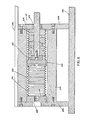
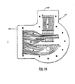
- the bellows displacement pump 60 is shown in Figure 7.
- the pump 60 may be used to obtain pressures ranging from a pressure just below atmospheric to a much higher pressure without appreciably contaminating the ebulliometric liquid.
- a base plate 600 may comprise a piece of aluminum stock having dimensions approximately 1.27 cm x 48.26 cm x 55.88 cm.
- An aluminum housing 602 is mounted between first and second end plates 604, 606, as shown in more detail in Figure 8.
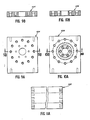
- the end plates 604, 606, shown in more detail in Figures 9A and 9B, and 10A and 10B, respectively, may each be fashioned from 1.27 cm x 8.9 cm x 10.80 cm aluminum plates.
- Each of the plates 604, 606 is screw-connected along one of its 8.90 cm edges to the base plate 600, thereby defining the bottom edges of the plates 604, 606.
- the end plate 606 is mounted about 1.59 cm from, and parallel to, one end of the base plate 600, the 1.59 cm being measured along the longest dimension of the base plate 600.
- the 8.90 cm dimension of the end plate 606 is approximately centered with respect to the 48.26 cm dimension of the base plate 600.
- the plates 604, 606 are mounted having the 8.90 cm x 10.80 cm faces of the plates parallel, with approximately 15.24 cm spacing between the nearest face to accommodate the housing 602.
- each plate is drilled with a 1.75 cm diameter hole centered between the edges along the 8.90 cm dimension of the plate and 4.45 cm from the top.
- An inner circle of six holes centered on a diameter of 3.56 cm is placed symmetrically and concentrically about the 1.75 cm hole. These holes are tapped into the plate 604.
- An outer ring of 12 holes centered on a circle of approximately 6.86 cm is also spaced symmetrically and concentrically about the 1.75 cm hole.
- the 8.90 cm top and bottom edges are each tapped with a pair of screw holes symmetrically placed approximately 6.86 cm apart.
- the screw holes on the bottom edges of the rear plate 604 and front plate 606 are used for screw mounting to the base plate 600.
- Figures 11A, 11B, and 11C show, respectively, side, horizontal cross-sectional, and end views of the housing 602, which is essentially a cylindrical aluminum tube approximately 15.24 cm long, 8.90 cm outer diameter, and 4.37 cm inner diameter.
- the ends of the housing 602 are tapped for screw mounting to the holes in the plates 604, 606 provided in the 6.86 cm diameter circle about the 1.75 cm holes.
- an aluminum top plate 608 approximately 0.64 cm x 8.90 cm x 28.58 cm is screw mounted to have one of its large faces flush with the top edges of the plates 604, 606.
- the top plate 608 may be placed to have one edge approximately flush with the large face of the plate 606 furthest from the plate 604 and also to be flush with the respective side edges of the plates 604, 606.
- An edge of the top plate 608 thereby projects approximately 10.80 cm beyond the outermost face of the plate 604.
- a welded bellows assembly 610 mounts within the housing 602.
- the bellows assembly comprises first and second bellows 612 and 614.
- Each of the bellows 612, 614 is manufactured from stainless steel bellows material approximately 0.015 cm thick, with an outer diameter of approximately 4.11 cm and an inner diameter of approximately 3.12 cm.
- Each of the bellows 612, 614 has a length of approximately 6.27 cm.
- the plug 616 is centre tapped along its axis with a cylindrical passage communicating between the ends of the plug 616, the passage having a diameter of approximately 1.90 cm and its axis substantially coincident with the axis of the plug 616.
- the outer face of the plug 616 has six threaded holes for screws centered on a circle having a diameter of 3.70 cm centered on the axis of the plug.
- the plug diameter in the specific construction is 4.11 cm and its thickness is 1.27 cm.
- the other end of the bellows 614 is welded to the edge of a face of a stainless steel cylindrically- shaped piston 618 having a diameter of 4.11 cm and a thickness of 1.27 cm as shown in more detail in Figures 14A, 14B, and 14C.
- this face of the piston 618 is characterized by a cylindrical hole having an axis substantially coincident with the piston axis, a diameter of approximately 0.64 cm, and extending 0.58 cm into the. piston from such face.
- six radial passages having axes approximately 60° apart communicate from the center hole to the periphery of the piston and are located approximately 0.42 cm behind such face.
- first bellows 612 One end of the first bellows 612, terminating on the bellows outer diameter, is welded to the edge of the other face of the piston 618.
- the inner diameter of the annulus 620 is chamfered away from the welded joint at an angle of 45°, thereby defining the inner face of the annulus 620 as the face having the larger inside diameter.
- a first face of the housing 602 has a hole 5.59 cm in diameter sunk approximately 0.15 cm, the hole being centered on the axis of the housing 602.
- An O-ring groove having a diameter of 4.84 cm is formed symmetrically around the hole in the first face of the housing 602 as shown in Figures 11A and 11 B.
- the bellows assembly 610 is fastened to the inner side of the second plate 606 by screws connecting through the inner circle of six holes in the second plate 606 to the corresponding circle of six holes in the stainless steel plug 616 which is disposed to match the circle of holes in the second plate 606, substantially as shown in Figure 8.
- the annulus 620 fits into the 5.59 cm hole formed in the housing 602.
- the first plate 604 fits snugly against the first face of the housing 602 and the annulus 620 and is fastened to the housing by screws as described earlier.
- a cylindrical aluminum block 622 having a. diameter of approximately 3.12 cm and a thickness of approximately 0.48 cm is screw-connected to the other face of the piston 618 utilizing the six screw holes shown in Figure 14A.
- the axes of the block 622 and the piston 618 are made substantially coincident.
- a threaded screw 624 is sunk into the block to project approximately 0.96 cm beyond the block 622 in the direction away from the piston 618, the screw 624 being substantially centered upon the axis of the block.
- One end of the 1.27 cm diameter steel shaft 626 is ground to the shape of a hexagon.
- the center of the hexagonal end is tapped to receive the screw 624.
- the hexagonal end of the shaft 626 is press fitted into a hole in the block 622 and then secured by the screw 624 as shown in Figure 8, the hole having a diameter of 0.80 cm.
- the shaft 626 which is approximately 24.13 cm long is threaded at its other end with 28 pitch threads.
- the shaft 626 passes concentrically through the central hole of the first plate 604.
- a lubricated bushing 628 having an outer diameter substantially equal to 1.75 cm and an inner diameter substantially equal to 1.27 cm provides a lubricated bearing surface for the shaft 626.
- the bushing 628 does not provide an airtight seal.
- the present invention also envisions modifications where the bushing 628 is replaced by an airtight seal.
- the sealed version permits pressurization of the interior of the rear bellows 612, thereby permitting the attainment of higher pressures in the fluorocarbon fluid without increase of the forces applied to the shaft 626.
- a pillow block 630 shown in Figures 16A and 16B, is made from a rectangular piece of aluminum stock approximately 2.54 cm x 8.90 cm x 10.80 cm.
- the pillow block is screw-connected to the base plate 600 and top plate 608 with the 8.90 cm x 10.80 cm face substantially parallel to the outer face of the plate 604.
- the 8.90 cm edges of the pillow block 630 contact the base plate 600 and top plate 608 with the outer face of the pillow block substantially flush with the end of the top plate 608.
- a 3.30 cm diameter hole having its center approximately 4.45 cm below the top of the pillow block 630 and substantially centered between the side edges of the pillow block 630 is drilled from the rear to the front of the pillow block.
- a sprocket 700 is rigidly attached to a shaft drive nut 702 and held in place by a first nut 704.
- a second nut 706 locks the shaft drive nut 702 against one face of a bearing 708.
- the bearing 708 is inserted into a receiving hole on one face of the pillow block 630, the receiving hole having a greater diameter and being concentric with the 3.30 cm diameter hole.
- the inner periphery of the shaft drive nut 702 is threaded to match the threaded end of the shaft 626 which is screwed into the shaft drive nut 702.
- One face of the bearing 708 rests against an inner face of the pillow block 630, the inner face terminating the receiving hole and being peripheral to the 3.30 cm diameter hole in the pillow block 630.
- the bearing 708 may be locked in place by a C-clip 710 in a suitably provided slot around the periphery of the receiving hole.
- Rotation of the sprocket 700 drives the shaft 626 back and forth in a horizontal direction, thereby providing expansion and contraction of the bellows 612, 614.
- a chain 720 may be used to connect the sprocket 700 to a driving sprocket 722.
- the driving sprocket 722 may be rotated by driving means such as the stepping motor 65.
- the microprocessor/controller 30 memory contains data on properties of ten different fluorocarbon liquids.
- the fluorocarbon reservoir 14 is filled with one of the designated liquids prior to operation.
- a correction factor is then dialed into the microprocessor/controller 30 by a thumbwheel 202 on the control panel shown in Figure 4.
- the correction factor is used by the microprocessor/controller 30 to correct hot spot temperatures measured in fluorocarbon liquid to equivalent air temperatures.
- the operator may also select a bulk operating temperature between -65°C and 150°C for the fluorocarbon and dial that into the microprocessor/controller 30 by a thumbwheel 204 on the face of the microprocessor/controller.
- the operator next turns on a heat switch 206 and a cool switch 208, sets a fill/drain switch 210 in the fill position, and puts a start/stop switch 212 in the start position to activate microprocessor control of system operation.
- the microprocessor/controller 30 first transmits a signal over the vacuum pump control line 52 to initiate operation of the vacuum pump 50, concurrently activating the solenoid control line 82 to open the port 72 from the manifold 16 to the vacuum pump and turning on an EVAC light 214.
- the vacuum pump 50 operating as a roughing pump, reduces the pressure in the exhaust manifold 16 and chamber 102 to a pressure of 400-667 Pa (3-5 mm Hg).
- the actual pressure is preselected in the microprocessor memory and is not critical as long as it is less than about 1333 Pa (10 mm Hg).
- the microprocessor/controller 30 monitors the pressure in the manifold over the lines 88 from the pressure transducer 89.
- the microprocessor/controller 30 causes the solenoid valve 24 in the coolant line 22 to open, concurrently with vacuum pump operation, to permit coolant to flow into the cooling system of the bubble cauldron 10 and exhaust to the air through the vent 27 as shown in Figure 3. Coolant flow is controlled to lower the cauldron temperature to approximately 16°C as determined from the thermocouple 108 over the thermocouple leads 34 to the microprocessor.
- the microprocessor/controller 30 contains a reference junction for the thermocouple 108.
- the vacuum pump 50 and EVAC light 214 are turned off.
- the pressure measured by the pressure transducer 89 in the manifold 16 at the time the vacuum pump is turned off is then read by the microprocessor/controller 30 and used as the zero level for subsequent pressure readings and calculations.
- the pressure transducer 89 may be a Celesco Model PLC manufactured by Transducer Products, Inc., 7800 Deering Ave., Canoga Park, California. A zero to 3.4 x 10 6 N/ M 2 range was selected for use in the specific construction described herein.
- the outputs from the pressure transducer 89 and the thermocouple 108 are amplified and fed to analog/digital converters. The digitized outputs are then read by the microprocessor part of the microprocessor/controller 30.
- the microprocessor/controller 30 activates the solenoid valve that closes the port 72 connected to the vacuum pump.
- the microprocessor/controller 30 next activates the solenoid valve controlling opening of the port 74 to permit fluorocarbon fluid to flow through the fluorocarbon fill line 20 into the manifold 16 and thence into the bubble cauldron 10 through the fluorocarbon transfer line 18.
- the microprocessor/controller 30 When the signal from the exclusive OR-gate 510 in the thermistor circuitry, Figure 5, goes low, the microprocessor/controller 30 activates the solenoid to close the port 74 connected to the fluorocarbon fluid fill line. At the same time the microprocessor/controller 30 activates the solenoid 24 to disable the cooling mode at the switch 208 and enable the bellows displacement pump 60 system by activating the solenoid to open the port 76 to the pressure line 62. The microprocessor/controller 30 then activates the heating coils 104 through the heating line 36 to raise the bulk temperature of the fluid in the cauldron 10 to the value previously set by the operator by use of the switch 204. A bus 40 from the microprocessor/controller 30 to the ribbon connectors 122 on the printed circuit board 110 is then activated to energize the device 100 under test.
- the system is now ready for hot spot detection.
- An operator uses the switch 64 to decrease the pressure in the cauldron 10 until the boiling is seen from the device 100 under test through the microscope 116.
- the boiling may be detected by direct observation of the device 100 under test in the microscope 116. Alternatively, the image may be viewed by means of a remote TV or other remote means.
- the switch 64 is used to increase the pressure on the fluid until all boiling is terminated except that from the last spot or spots to stop boiling, that is, the hottest spot or spots. At this point the bubble sizes will be small, and the appearance of the device 100 under test will be as indicated in idealized view in Figure 6, where a single bubble stream 300 is indicated.
- An elevation view of the bubble field rising from the device 100 may be substantially as indicated in Figure 6A.
- the operator may now slowly increase the pressure until the bubble stream 300 arising from the device 100 is just quenched. At this time he may activate a hold switch 216 on the control panel of the microprocessor/controller 30 and the microprocessor/ controller 30 will then store signals indicative of the pressure from the transducer line 88 and the bulk liquid temperature from the thermocouple line 34.
- the data may be displayed on a display 218 on the control panel, as selected by a switch 220.
- the nucleate boiling point of the fluorocarbon selected with a fluid select switch 22 may also be read out of table stored in the memory of the microprocessor/controller 30.
- the whirligig 130 is a combined heater/thermocouple.
- a hot spot 132 is provided at the position where the thermocouple wires cross.
- the thermocouple provides a continuous measurement of the hot spot temperature.
- the temperature of the hot spot is increased until boiling from the hot spot is observed with the pressure maintained at the pressure where boiling was just quenched from the device 100. Because of the liquid superheating effects boiling will ordinarily commence at a temperature higher than the boiling point of the liquid. Superheating effects are avoided in the present application by first observing the presence of boiling and then raising the pressure or lowering the temperature until boiling just ceases. Thus, in the present application of the whirligig 130, the temperature of the hot spot 132 is first raised to the point where boiling commences and then lowered to the point where observation of the bubble stream arising from the hot spot 132 shows that nucleate boiling has just been quenched.
- the temperature of the hot spot 132 is then recorded from the whirligig 130 by the microprocessor/ controller 30. At the same time, the heating current in the whirligig 130 is also measured. Subsequently, after the cauldron 10 has been evacuated of fluid, the whirligig 130 may be rerun in air with the previously observed heating current, and the hot spot 132 temperature in air measured by the whirligig. This temperature will then be an approximation of the air temperature of the hot spot on the device being tested.
- means 800 indicated symbolically in Figure 3, which sense the presence of boiling other than optically also fall within the scope of the present invention.
- Conversion tables may be made up and stored in the microprocessor/controller 30 to relate liquid boiling points at various pressures to equivalent hot spot temperatures in air.
- tables may be compiled from experimental determinations of comparative liquid/air device temperatures where device temperatures are determined by lower resolution techniques.
- any particular coolant is not an essential feature of the invention.
- Various coolants such as circulating ice water, or liquid N 2 , could be used.
- a closed cycle refrigeration system may be used for cooling.
Landscapes
- Physics & Mathematics (AREA)
- General Physics & Mathematics (AREA)
- Health & Medical Sciences (AREA)
- Life Sciences & Earth Sciences (AREA)
- Chemical & Material Sciences (AREA)
- Analytical Chemistry (AREA)
- Biochemistry (AREA)
- General Health & Medical Sciences (AREA)
- Immunology (AREA)
- Pathology (AREA)
- Investigating Or Analyzing Materials Using Thermal Means (AREA)
- Control Of Combustion (AREA)
- Measuring Fluid Pressure (AREA)
- Fire-Detection Mechanisms (AREA)
- Measuring Pulse, Heart Rate, Blood Pressure Or Blood Flow (AREA)
- Tests Of Electronic Circuits (AREA)
- Semiconductor Integrated Circuits (AREA)
- Testing Of Individual Semiconductor Devices (AREA)
- Geophysics And Detection Of Objects (AREA)
- Air Bags (AREA)
- Transition And Organic Metals Composition Catalysts For Addition Polymerization (AREA)
- Polyesters Or Polycarbonates (AREA)
Claims (25)
Priority Applications (1)
| Application Number | Priority Date | Filing Date | Title |
|---|---|---|---|
| AT83900236T ATE22977T1 (de) | 1981-12-01 | 1982-11-26 | Detektor fuer den waermsten punkt mittels siedepunktsfeststellung. |
Applications Claiming Priority (2)
| Application Number | Priority Date | Filing Date | Title |
|---|---|---|---|
| US326224 | 1981-12-01 | ||
| US06/326,224 US4466746A (en) | 1981-12-01 | 1981-12-01 | Ebulliometric hot spot detector |
Publications (3)
| Publication Number | Publication Date |
|---|---|
| EP0094966A1 EP0094966A1 (de) | 1983-11-30 |
| EP0094966A4 EP0094966A4 (de) | 1984-04-06 |
| EP0094966B1 true EP0094966B1 (de) | 1986-10-15 |
Family
ID=23271321
Family Applications (1)
| Application Number | Title | Priority Date | Filing Date |
|---|---|---|---|
| EP83900236A Expired EP0094966B1 (de) | 1981-12-01 | 1982-11-26 | Detektor für den wärmsten punkt mittels siedepunktsfeststellung |
Country Status (18)
| Country | Link |
|---|---|
| US (1) | US4466746A (de) |
| EP (1) | EP0094966B1 (de) |
| JP (1) | JPS58502064A (de) |
| KR (1) | KR910008823B1 (de) |
| AT (1) | ATE22977T1 (de) |
| AU (1) | AU1100283A (de) |
| BR (1) | BR8208000A (de) |
| CA (1) | CA1186526A (de) |
| DE (1) | DE3273835D1 (de) |
| GB (1) | GB2110823B (de) |
| IE (1) | IE53723B1 (de) |
| IL (1) | IL67307A (de) |
| IN (1) | IN157325B (de) |
| IT (1) | IT1200509B (de) |
| MX (1) | MX158366A (de) |
| NZ (1) | NZ202509A (de) |
| PH (1) | PH20743A (de) |
| WO (1) | WO1983001989A1 (de) |
Families Citing this family (15)
| Publication number | Priority date | Publication date | Assignee | Title |
|---|---|---|---|---|
| DE3410789A1 (de) * | 1984-03-23 | 1985-09-26 | Siemens AG, 1000 Berlin und 8000 München | Verfahren zur orientierung einer fluessigkristallinen substanz bezueglich einer unterlage |
| US4640626A (en) * | 1984-09-13 | 1987-02-03 | Siemens Aktiengesellschaft | Method and apparatus for localizing weak points within an electrical circuit |
| US4710707A (en) * | 1985-01-16 | 1987-12-01 | Zenith Electronics Corporation | High voltage electronic component test apparatus |
| DE3600421A1 (de) * | 1986-01-09 | 1987-07-16 | Kraftwerk Union Ag | Verfahren und vorrichtung zur feststellung und ortung von lokalen uebererwaermungen in fluessigkeits-gekuehlten wicklungen elektrischer maschinen |
| US4964737A (en) * | 1989-03-17 | 1990-10-23 | Ibm | Removable thermocouple template for monitoring temperature of multichip modules |
| US5004973A (en) * | 1989-07-13 | 1991-04-02 | Thermal Management, Inc. | Method and apparatus for maintaining electrically operating device temperatures |
| US5119021A (en) * | 1989-07-13 | 1992-06-02 | Thermal Management, Inc. | Method and apparatus for maintaining electrically operating device temperatures |
| US5396068A (en) * | 1993-03-30 | 1995-03-07 | At&T Corp. | Method of making a semiconductor device including infrared imaging, and apparatus for use in the imaging |
| US5504017A (en) * | 1994-12-20 | 1996-04-02 | Advanced Micro Devices, Inc. | Void detection in metallization patterns |
| GB9706990D0 (en) | 1997-04-05 | 1997-05-21 | Univ Heriot Watt | Dew point and bubble point measurement |
| US6033107A (en) * | 1997-07-15 | 2000-03-07 | Temptronic Corporation | Temperature mapping system |
| US6559670B1 (en) * | 1999-11-16 | 2003-05-06 | Lsi Logic Corporation | Backside liquid crystal analysis technique for flip-chip packages |
| US6842021B1 (en) * | 2003-11-07 | 2005-01-11 | National Semiconductor Corporation | System and method for detecting location of a defective electrical connection within an integrated circuit |
| US20110094556A1 (en) * | 2009-10-25 | 2011-04-28 | Digital Angel Corporation | Planar thermoelectric generator |
| US10600664B2 (en) | 2017-05-03 | 2020-03-24 | Applied Materials, Inc. | Fluorescence based thermometry for packaging applications |
Family Cites Families (6)
| Publication number | Priority date | Publication date | Assignee | Title |
|---|---|---|---|---|
| US2578265A (en) * | 1948-10-11 | 1951-12-11 | Milton Roy Co | Bellows pump |
| US3264863A (en) * | 1963-05-27 | 1966-08-09 | Maropis Nicholas | Method and apparatus for detecting incipient boiling of a liquid |
| US3361037A (en) * | 1965-10-21 | 1968-01-02 | Holley Carburetor Co | Fail-safe pressur responsive device |
| US3396335A (en) * | 1966-08-26 | 1968-08-06 | Circuit Res Company | Method of testing printed circuit conductors |
| US3510762A (en) * | 1967-04-14 | 1970-05-05 | John Robert Alexander Leslie | Electrical cable temperature monitoring and hot-spot locating system and method utilizing a transmission line having a liquid dielectric |
| JPS5651631A (en) * | 1979-10-02 | 1981-05-09 | Chiyou Lsi Gijutsu Kenkyu Kumiai | Measuring instrument for surface temperature distribution |
-
1981
- 1981-12-01 US US06/326,224 patent/US4466746A/en not_active Expired - Lifetime
-
1982
- 1982-11-16 NZ NZ202509A patent/NZ202509A/en unknown
- 1982-11-18 IL IL67307A patent/IL67307A/xx not_active IP Right Cessation
- 1982-11-23 GB GB08233329A patent/GB2110823B/en not_active Expired
- 1982-11-26 BR BR8208000A patent/BR8208000A/pt not_active IP Right Cessation
- 1982-11-26 AT AT83900236T patent/ATE22977T1/de active
- 1982-11-26 JP JP83500258A patent/JPS58502064A/ja active Pending
- 1982-11-26 DE DE8383900236T patent/DE3273835D1/de not_active Expired
- 1982-11-26 EP EP83900236A patent/EP0094966B1/de not_active Expired
- 1982-11-26 AU AU11002/83A patent/AU1100283A/en not_active Abandoned
- 1982-11-26 WO PCT/US1982/001660 patent/WO1983001989A1/en not_active Ceased
- 1982-11-30 MX MX195399A patent/MX158366A/es unknown
- 1982-11-30 KR KR8205369A patent/KR910008823B1/ko not_active Expired
- 1982-11-30 IE IE2846/82A patent/IE53723B1/en not_active IP Right Cessation
- 1982-11-30 IT IT49590/82A patent/IT1200509B/it active
- 1982-12-01 PH PH28212A patent/PH20743A/en unknown
- 1982-12-01 IN IN1401/CAL/82A patent/IN157325B/en unknown
- 1982-12-01 CA CA000416761A patent/CA1186526A/en not_active Expired
Also Published As
| Publication number | Publication date |
|---|---|
| KR910008823B1 (ko) | 1991-10-21 |
| EP0094966A4 (de) | 1984-04-06 |
| IE53723B1 (en) | 1989-01-18 |
| IN157325B (de) | 1986-03-01 |
| AU1100283A (en) | 1983-06-17 |
| BR8208000A (pt) | 1983-10-18 |
| WO1983001989A1 (en) | 1983-06-09 |
| IE822846L (en) | 1983-06-01 |
| KR840002522A (ko) | 1984-07-02 |
| IL67307A (en) | 1988-03-31 |
| GB2110823B (en) | 1985-08-21 |
| JPS58502064A (ja) | 1983-12-01 |
| IT8249590A0 (it) | 1982-11-30 |
| NZ202509A (en) | 1985-11-08 |
| EP0094966A1 (de) | 1983-11-30 |
| ATE22977T1 (de) | 1986-11-15 |
| IL67307A0 (en) | 1983-03-31 |
| US4466746A (en) | 1984-08-21 |
| IT1200509B (it) | 1989-01-18 |
| DE3273835D1 (de) | 1986-11-20 |
| GB2110823A (en) | 1983-06-22 |
| CA1186526A (en) | 1985-05-07 |
| PH20743A (en) | 1987-04-02 |
| MX158366A (es) | 1989-01-27 |
Similar Documents
| Publication | Publication Date | Title |
|---|---|---|
| EP0094966B1 (de) | Detektor für den wärmsten punkt mittels siedepunktsfeststellung | |
| US3798960A (en) | Automatic viscometer with multiple capillary viscometer tube | |
| US5824889A (en) | Capacitive oil deterioration and contamination sensor | |
| US5908985A (en) | Microprocessor-based liquid sensor and ice detector | |
| JP5311577B2 (ja) | 圧力センサの検査装置 | |
| CN104880436B (zh) | 一种薄膜高温光电物性测试装置 | |
| US5713666A (en) | Thermal testing apparatus and method | |
| US4117712A (en) | Emissimeter and method of measuring emissivity | |
| EP0805968B1 (de) | Echtzeitmessverfahren | |
| US5838445A (en) | Method and apparatus for determining surface roughness | |
| US4726688A (en) | Monitored background radiometer | |
| US4862733A (en) | Method and apparatus for detecting leaks in a liquid-containing tank | |
| JPH11237356A (ja) | 流体識別方法及び流体識別装置 | |
| US4781057A (en) | Method and apparatus for detecting leaks in a liquid-containing tank | |
| US4187723A (en) | Liquid nitrogen level indicator | |
| EP0223742B1 (de) | Vorrichtung und Verfahren zur Bestimmung des Siedepunktes von Flüssigkeiten, insbesondere zur Bestimmung des Siedepunktes von nicht-eutektischen wässrigen Mischungen | |
| US4541730A (en) | Apparatus and method for testing evacuatable dewar vessels | |
| US20230296445A1 (en) | Stacked Active Thick Film Device | |
| CN212180227U (zh) | 光学测试控制装置 | |
| US5040416A (en) | Electrical current flow sensor | |
| CN223373209U (zh) | 衬底处理装置及衬底测温组件 | |
| US5356216A (en) | Apparatus for measuring heat of circuit module | |
| CN221077751U (zh) | 一种玻璃量器容量测验装置 | |
| JPH05281073A (ja) | ピラニ真空計 | |
| CN117870909A (zh) | 液氮/液氦到室温自动温度循环的温度计筛选装置及方法 |
Legal Events
| Date | Code | Title | Description |
|---|---|---|---|
| PUAI | Public reference made under article 153(3) epc to a published international application that has entered the european phase |
Free format text: ORIGINAL CODE: 0009012 |
|
| AK | Designated contracting states |
Designated state(s): AT BE CH DE FR GB LI NL SE |
|
| 17P | Request for examination filed |
Effective date: 19831001 |
|
| GRAA | (expected) grant |
Free format text: ORIGINAL CODE: 0009210 |
|
| AK | Designated contracting states |
Kind code of ref document: B1 Designated state(s): AT BE CH DE FR GB LI NL SE |
|
| PG25 | Lapsed in a contracting state [announced via postgrant information from national office to epo] |
Ref country code: BE Effective date: 19861015 Ref country code: AT Effective date: 19861015 |
|
| REF | Corresponds to: |
Ref document number: 22977 Country of ref document: AT Date of ref document: 19861115 Kind code of ref document: T |
|
| REF | Corresponds to: |
Ref document number: 3273835 Country of ref document: DE Date of ref document: 19861120 |
|
| ET | Fr: translation filed | ||
| PLBE | No opposition filed within time limit |
Free format text: ORIGINAL CODE: 0009261 |
|
| STAA | Information on the status of an ep patent application or granted ep patent |
Free format text: STATUS: NO OPPOSITION FILED WITHIN TIME LIMIT |
|
| 26N | No opposition filed | ||
| PGFP | Annual fee paid to national office [announced via postgrant information from national office to epo] |
Ref country code: SE Payment date: 19931116 Year of fee payment: 12 |
|
| PGFP | Annual fee paid to national office [announced via postgrant information from national office to epo] |
Ref country code: CH Payment date: 19931123 Year of fee payment: 12 |
|
| PG25 | Lapsed in a contracting state [announced via postgrant information from national office to epo] |
Ref country code: SE Effective date: 19941127 |
|
| PG25 | Lapsed in a contracting state [announced via postgrant information from national office to epo] |
Ref country code: LI Effective date: 19941130 Ref country code: CH Effective date: 19941130 |
|
| EAL | Se: european patent in force in sweden |
Ref document number: 83900236.7 |
|
| REG | Reference to a national code |
Ref country code: CH Ref legal event code: PL |
|
| EUG | Se: european patent has lapsed |
Ref document number: 83900236.7 |
|
| PGFP | Annual fee paid to national office [announced via postgrant information from national office to epo] |
Ref country code: FR Payment date: 19981030 Year of fee payment: 17 |
|
| PGFP | Annual fee paid to national office [announced via postgrant information from national office to epo] |
Ref country code: GB Payment date: 19981120 Year of fee payment: 17 |
|
| PGFP | Annual fee paid to national office [announced via postgrant information from national office to epo] |
Ref country code: NL Payment date: 19981130 Year of fee payment: 17 |
|
| PGFP | Annual fee paid to national office [announced via postgrant information from national office to epo] |
Ref country code: DE Payment date: 19990129 Year of fee payment: 17 |
|
| PG25 | Lapsed in a contracting state [announced via postgrant information from national office to epo] |
Ref country code: GB Free format text: LAPSE BECAUSE OF NON-PAYMENT OF DUE FEES Effective date: 19991126 |
|
| PG25 | Lapsed in a contracting state [announced via postgrant information from national office to epo] |
Ref country code: NL Free format text: LAPSE BECAUSE OF NON-PAYMENT OF DUE FEES Effective date: 20000601 |
|
| GBPC | Gb: european patent ceased through non-payment of renewal fee |
Effective date: 19991126 |
|
| PG25 | Lapsed in a contracting state [announced via postgrant information from national office to epo] |
Ref country code: FR Free format text: LAPSE BECAUSE OF NON-PAYMENT OF DUE FEES Effective date: 20000731 |
|
| NLV4 | Nl: lapsed or anulled due to non-payment of the annual fee |
Effective date: 20000601 |
|
| PG25 | Lapsed in a contracting state [announced via postgrant information from national office to epo] |
Ref country code: DE Free format text: LAPSE BECAUSE OF NON-PAYMENT OF DUE FEES Effective date: 20000901 |
|
| REG | Reference to a national code |
Ref country code: FR Ref legal event code: ST |