EP0805968B1 - Echtzeitmessverfahren - Google Patents
Echtzeitmessverfahren Download PDFInfo
- Publication number
- EP0805968B1 EP0805968B1 EP95935485A EP95935485A EP0805968B1 EP 0805968 B1 EP0805968 B1 EP 0805968B1 EP 95935485 A EP95935485 A EP 95935485A EP 95935485 A EP95935485 A EP 95935485A EP 0805968 B1 EP0805968 B1 EP 0805968B1
- Authority
- EP
- European Patent Office
- Prior art keywords
- temperature
- sensor
- medium
- thermal conductivity
- thermal
- Prior art date
- Legal status (The legal status is an assumption and is not a legal conclusion. Google has not performed a legal analysis and makes no representation as to the accuracy of the status listed.)
- Expired - Lifetime
Links
- 238000000034 method Methods 0.000 title claims description 31
- 230000008859 change Effects 0.000 claims description 30
- 238000005259 measurement Methods 0.000 claims description 27
- 230000003044 adaptive effect Effects 0.000 claims description 3
- 238000011109 contamination Methods 0.000 claims description 3
- 238000013213 extrapolation Methods 0.000 claims description 2
- 230000036962 time dependent Effects 0.000 claims 2
- 238000005260 corrosion Methods 0.000 claims 1
- 230000007797 corrosion Effects 0.000 claims 1
- BASFCYQUMIYNBI-UHFFFAOYSA-N platinum Chemical compound [Pt] BASFCYQUMIYNBI-UHFFFAOYSA-N 0.000 description 20
- 230000006870 function Effects 0.000 description 14
- 229910052697 platinum Inorganic materials 0.000 description 10
- 238000010438 heat treatment Methods 0.000 description 6
- 230000000694 effects Effects 0.000 description 5
- 238000004364 calculation method Methods 0.000 description 4
- 238000012937 correction Methods 0.000 description 4
- PNEYBMLMFCGWSK-UHFFFAOYSA-N Alumina Chemical compound [O-2].[O-2].[O-2].[Al+3].[Al+3] PNEYBMLMFCGWSK-UHFFFAOYSA-N 0.000 description 3
- 238000001816 cooling Methods 0.000 description 3
- 239000007788 liquid Substances 0.000 description 3
- 239000007791 liquid phase Substances 0.000 description 3
- 238000012423 maintenance Methods 0.000 description 3
- 239000012071 phase Substances 0.000 description 3
- 230000004044 response Effects 0.000 description 3
- 239000007787 solid Substances 0.000 description 3
- XLYOFNOQVPJJNP-UHFFFAOYSA-N water Substances O XLYOFNOQVPJJNP-UHFFFAOYSA-N 0.000 description 3
- PXHVJJICTQNCMI-UHFFFAOYSA-N Nickel Chemical compound [Ni] PXHVJJICTQNCMI-UHFFFAOYSA-N 0.000 description 2
- 230000003321 amplification Effects 0.000 description 2
- 238000009529 body temperature measurement Methods 0.000 description 2
- 239000003990 capacitor Substances 0.000 description 2
- 230000007423 decrease Effects 0.000 description 2
- 230000004069 differentiation Effects 0.000 description 2
- 239000006260 foam Substances 0.000 description 2
- 239000000463 material Substances 0.000 description 2
- 238000012544 monitoring process Methods 0.000 description 2
- 238000003199 nucleic acid amplification method Methods 0.000 description 2
- 230000005855 radiation Effects 0.000 description 2
- 239000004065 semiconductor Substances 0.000 description 2
- 239000000725 suspension Substances 0.000 description 2
- RYGMFSIKBFXOCR-UHFFFAOYSA-N Copper Chemical compound [Cu] RYGMFSIKBFXOCR-UHFFFAOYSA-N 0.000 description 1
- BQCADISMDOOEFD-UHFFFAOYSA-N Silver Chemical compound [Ag] BQCADISMDOOEFD-UHFFFAOYSA-N 0.000 description 1
- 239000000443 aerosol Substances 0.000 description 1
- 230000032683 aging Effects 0.000 description 1
- 239000004411 aluminium Substances 0.000 description 1
- 229910052782 aluminium Inorganic materials 0.000 description 1
- XAGFODPZIPBFFR-UHFFFAOYSA-N aluminium Chemical compound [Al] XAGFODPZIPBFFR-UHFFFAOYSA-N 0.000 description 1
- 238000004422 calculation algorithm Methods 0.000 description 1
- 239000011248 coating agent Substances 0.000 description 1
- 238000000576 coating method Methods 0.000 description 1
- 238000007796 conventional method Methods 0.000 description 1
- 239000010949 copper Substances 0.000 description 1
- 229910052802 copper Inorganic materials 0.000 description 1
- 230000008878 coupling Effects 0.000 description 1
- 238000010168 coupling process Methods 0.000 description 1
- 238000005859 coupling reaction Methods 0.000 description 1
- 230000001419 dependent effect Effects 0.000 description 1
- 238000001514 detection method Methods 0.000 description 1
- 238000001035 drying Methods 0.000 description 1
- 230000005670 electromagnetic radiation Effects 0.000 description 1
- 239000000839 emulsion Substances 0.000 description 1
- 239000012530 fluid Substances 0.000 description 1
- 239000012535 impurity Substances 0.000 description 1
- 239000010687 lubricating oil Substances 0.000 description 1
- 229910052751 metal Inorganic materials 0.000 description 1
- 239000002184 metal Substances 0.000 description 1
- 239000000203 mixture Substances 0.000 description 1
- 229910052759 nickel Inorganic materials 0.000 description 1
- 230000000737 periodic effect Effects 0.000 description 1
- 239000000843 powder Substances 0.000 description 1
- 229910052709 silver Inorganic materials 0.000 description 1
- 239000004332 silver Substances 0.000 description 1
- 239000008279 sol Substances 0.000 description 1
- 230000006641 stabilisation Effects 0.000 description 1
- 238000011105 stabilization Methods 0.000 description 1
- 229910052715 tantalum Inorganic materials 0.000 description 1
- 238000010792 warming Methods 0.000 description 1
Images
Classifications
-
- G—PHYSICS
- G01—MEASURING; TESTING
- G01N—INVESTIGATING OR ANALYSING MATERIALS BY DETERMINING THEIR CHEMICAL OR PHYSICAL PROPERTIES
- G01N25/00—Investigating or analyzing materials by the use of thermal means
- G01N25/18—Investigating or analyzing materials by the use of thermal means by investigating thermal conductivity
Definitions
- the invention relates to a real-time adaptive measuring method for determining the thermal conductivity K between a sensor and a medium, and for determining the temperature of the medium by means of the sensor that is in a thermal exchange relation with the medium, by changing the temperature of the sensor by means of supplying thermal power to the sensor and by measuring the thermal power supplied to the sensor.
- thermoanemometers for measuring changes in thermal conductivity are based on the use of either two or one temperature element.
- one of the elements is heated and the power used for heating is simultaneously determined, whereas the other element is used to determine the temperature of the medium to be measured.
- Devices utilizing two temperature elements are divided into two groups according to their operation. In one group, constant power is supplied to the element to be heated and the temperature difference between the elements is measured. In the more common arrangement, the temperature difference between the elements is kept constant and the thermal power required for this purpose is determined. The latter method is more advantageous in that the rate at which the device responds to changes in the quantity to be measured increases in proportion to the amplification of a feedback loop used for adjusting the temperature difference between the elements.
- Devices utilizing one temperature element are based either on the observation of the cooling or warm-up rate of the element or on the determination of the thermal power required for maintaining the sensor at the desired temperature.
- the former method corresponds to a method of two sensors wherein constant power is supplied to the element to be heated and the temperature difference between the elements is measured.
- the latter method mainly corresponds to a method of two elements wherein the temperature difference between the elements is kept constant and the thermal power required for this purpose is determined.
- the problem with utilizing one element is that the temperature of the medium is not known, wherefore the power required to maintain the sensor at the desired temperature depends not only on the thermal conductivity of the medium, but also for example on changes in the temperature of the medium, and their effects cannot be distinguished from one another.
- US Patent 5,117,691 discloses a one-sensor measuring method that is based on differentiation and that operates without information about the surrounding temperature.
- the invention according to the present application is based on correlation checking that as an essential part comprises determining the temperature of the medium through calculation. Another significant difference compared to the method of the US patent is that the measurement takes place in real time.
- the method according to the present invention operates in real time, wherefore no such steady state that is described in the aforementioned US patent and that prevents measurement in real time is required.
- the device according to the US patent can also be realized in such a way that the temperature of the sensor is not required to stabilize and reach the steady state, but in such a case a demodulator is utilized in the circuit, wherefore measurement results cannot be obtained in real time.
- thermoanemometers utilizing two temperature sensors is the maintenance of their calibration within a wide temperature range.
- measurement is based on measuring the temperature difference between two temperature sensors, their readings must follow each other very closely within the entire operating temperature range. This requires the use of expensive precision components and it still sometimes causes problems for example due to the ageing of components, heat radiation or warming caused by the electronics.
- thermoanemometer with two temperature sensors, wherein the thermal power is kept constant and the temperature difference between the temperature sensors is measured.
- response time is shortened by keeping the temperature difference between the temperature sensors constant through the adjustment of the thermal power.
- the speed of the thermoanemometer then increases in proportion to the amplification coefficient used in the adjustment.
- the thermal capacity C of the sensor is assumed to be known or at least constant. Furthermore, the signal-to-noise ratio is poor since the temperature difference between the sensor and the medium is reduced during the measurement, but the noise level remains constant.
- the purpose of the invention is to make it possible to measure the temperature of the medium with one temperature sensor. It is then possible to distinguish between those changes in the thermal power that are caused by a property of the medium to be measured, such as flow rate or moisture, and those caused by changes in the temperature of the medium. Furthermore, it is possible to eliminate the requirement concerning the mutual precision of the two temperature elements used in the conventional measurement. Another objective is to provide a simpler and more economical structure than conventionally. Another purpose of the invention is to eliminate the slowness of the sensors of the conventional one temperature element, and the requirement that the thermal capacity of the sensor must be known beforehand or that at least it must be constant.
- the method according to the invention is also adaptive, i.e. the operation can easily be changed according to the conditions.
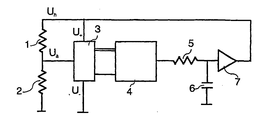
- the figure of the drawing shows a measuring arrangement implementing the method according to the invention.
- a voltage U a is used to heat a platinum resistor 2 (Pt100) provided in the medium to be measured.
- the positive reference voltage U + of an A/D converter 3 is connected to the voltage U h and, correspondingly, U + is connected to the earth so that the A/D converter 3 directly measures the ratio U a /U h .
- a program which reads the resistance, and therefore information about the temperature T a , of the platinum resistor 2 from the A/D converter 3, and which compares it with the desired value operates in a processor 4. If the temperature is too low, the program makes the output port rise so that it controls, via a low pass filter formed by a resistor 5 and a capacitor 6, an amplifier 7 controlling the heating voltage U h . Correspondingly, if the measured temperature T a of the platinum resistor 2 is too high, the output port is lowered so that the heating voltage decreases. With the present processors, this function can easily be performed for example hundreds of times per second, so that in practice the operation is continuous.
- the thermal conductivity and/or thermal capacity of the sensor can be calculated at the same frequency or at a frequency that is for example one decade lower, and the desired quantities, such as the flow rate or moisture of the medium, can be further calculated utilizing the former quantities.
- the resistor 5 and the capacitor 6 are unnecessary and the analog output of the D/A converter of the processor can be used to directly control the amplifier 7.
- an external A/D converter 3 is naturally unnecessary. If the capacity of the D/A converter of the processor to supply current is sufficient, the amplifier 7 can also be eliminated. In such a case the device according to the invention only comprises three components: a processor 4, a temperature element 2 and a resistor 1.
- the voltage U h is known since the program provides its set value.
- the resistance and the temperature data of the platinum resistor 2, i.e. the temperature sensor, is obtained from the A/D converter 3, wherefore the power P tot required for heating can be calculated.
- the temperature T a of the platinum resistor 2 is adjusted by means of software and the correlation of the thermal conductivity K e with this temperature is calculated, the correct value T s for the temperature estimate T e of the medium can be determined.
- Changing the voltage U h alters the temperature T a of the temperature sensor 2.
- the temperature T a can resemble for example a sine function, a saw tooth function, an exponential/rectangular function or some other periodic or aperiodic function.
- the moving average of the temperature T a can also change slowly, compensating for the changes in the temperature of the medium.
- the difference between the temperature of the sensor T a and the temperature of the medium T s can also be altered in a desired manner for example in order to change the precision of the measurement or the current consumption of the device.
- the power P k needed to maintain the temperature T a of the temperature sensor 2 changes, it results from either a change in the thermal conductivity between the sensor and the medium or from a change in the temperature of the medium, or both.
- a change of temperature is detected with the above-described correlation checkings that are performed sufficiently frequently, and the change of power possibly remaining after the checking can be ascribed to a change in the thermal conductivity, and therefore this information can be utilized in the equation disclosed below for solving the thermal conductivity.
- the example given employs a platinum resistor because it is widely used and because it can be heated with a current that is conducted directly through it.
- a nickel resistor or for example a piece of metal wire of arbitrary length, a film vaporized on a surface, a semiconductor component, i.e. any device having electrical properties that are a function of temperature, can be utilized equally well.
- the component measuring the temperature and the component used to heat and/or cool it are separate, for example a combination of a platinum resistor and a heating resistor, or a combination of a semiconductor component and a Peltier element. It is required of such a combination that the thermal conductivity between the sensors used for heating and for temperature measurement is high.
- the temperature of the sensor is measured externally for example on the basis of the infrared radiation the sensor produces.
- the sensor can also be heated externally for example by means of electromagnetic radiation.
- the medium may be for example a gas, vapour, liquid, solid or a heterogenous system formed by several phases, such as a sol, emulsion, aerosol, foam or a macroscopic phase formed by two liquids, or for example a solid piece in gas, having a surface to which the sensor is attached, or a fluid or gas flowing in a tube, the flow rate being measured with a sensor according to the present invention attached to the exterior of the tube.
- the total power P tot thus consists of two parts P k and P c , which are used to maintain the temperature of the sensor at a certain constant level and to change it at the desired rate.
- the power refers to thermal power, wherefore it may also be negative for example if the sensor is at a lower temperature than the medium, or if the rate of change dT a /dt of the sensor temperature acquires a sufficiently high negative value.
- the total power P tot and the temperature T a of the sensor can be measured at desired moments t.
- the unknowns K, C and T s are to be solved from the equation.
- the temperature of the sensor is a certain time function, and the power to be supplied to the sensor is adjusted, as required, in order to keep the temperature of the sensor at a desired level at each moment. Since P c is proportionate to the rate of change dT a /dt of the sensor temperature T a and to the temperature difference T a -T s between the sensor and the medium, selecting T s suitably as a time function enables the differentiation between the determination of the aforementioned two powers, and thus between the determination of the thermal conductivity and the thermal capacity.
- the primary target of interest is the measurement of the thermal conductivity
- the effect of the correlation between the temperature T a of a sensor of a certain size and the calculated thermal conductivity K e on the determined value of K e is known, it is not necessary to correct the temperature estimate T e of the medium, but the value K e calculated for the thermal conductivity can be directly corrected with an amount that is a known function of correlation.
- the thermal conductivity K is first determined when the temperature of the sensor is T a .
- the temperature T a of the sensor is changed with a differentially small amount dT a during dt.
- P tot -P k in the numerator represents the change of power that is required to alter the temperature of the sensor at the speed of dT a /dt, compared to a situation wherein the temperature of the sensor remains constant.
- the thermal conductivity K is known when the thermal capacity is being measured, since C can also be determined for example in the following manner.
- the invention is suitable for determining the thermal conductivity and thermal capacity of the sensor and the medium simultaneously with determining the temperature.
- the thermal conductivity of the medium may change for example due to a change in the flow conditions or due to changing properties of the medium.
- the thermal capacity may change for example due to contamination of the sensor or due to a change in the properties of the medium.
- Suitable applications of the invention include for example measuring the flow rate of the medium, indicating touch, determining moisture content, measuring pressure, measuring gas moisture, measuring thermal properties through a tube wall, and determining levels of containers.
- King's law can be specified to take into account for example the turbulence, viscosity, moisture and pressure of the medium without any effect on the principle of the method.
- the invention is also highly applicable to the measurement of flow rate through the tube wall.
- the sensor is connected thermally to the tube wall, so that the tube has approximately the temperature T a of the sensor.
- the situation corresponds to what is described above, except that unlike in the case above, heat is here transferred between the sensor and the surroundings with the power P v , since the sensor is not entirely surrounded by the medium to be measured.
- the measurement resumes the normal form wherein the sensor is entirely surrounded by the medium.
- Measurement through the tube wall enables easy post-assembly and maintenance, the system is strong and it does not affect the flow of the matter in the tube. Furthermore, the amount of contamination gathering on the inner surface of the tube can be estimated by measuring the thermal capacity.
- Touch is indicated by immersing the temperature sensor in a structure having thermal conductivity and thermal capacity that change when the surface of the material is touched, and the touch can be detected regardless of the temperature of the object that is touching.
- An increase in moisture usually improves the thermal conductivity of the medium, and this can be detected with the method according to the invention.
- Useful applications include for example plant cultivation and monitoring the drying of structures for example in connection with concreting and water damages. A change in the surrounding temperature does not affect the measurement.
- the thermal capacity of the gas increases, and this can be measured. It is easiest to perform such measurement if the gas to be measured surrounding the sensor is immobile. This can be implemented for example by surrounding the sensor with a measuring chamber which is connected to the pressure to be measured via a capillary tube. The immobility of the gas is not necessary, however.
- the measurement of the gas moisture is performed by coating or filling the sensor with a suitable hygroscopic matter which absorbs the more water the greater the atmospheric moisture is.
- the method enables the detection of a change in the thermal capacity of the hygroscopic matter in the sensor.
- Another method is to measure the thermal capacity of the sensor and to keep it constant by changing the temperature of the sensor, whereupon the required temperature is a function of moisture.
- Thermal properties can be measured through the tube wall by thermally connecting the sensor to the tube wall.
- Suitable properties of the tube wall are good thermal conductivity between the inner and outer surface of the wall, but poor thermal conductivity in the direction of the tube wall (for example tubes with thin walls and tubes of thermally anisotropic material).
- heat tends to be transferred between the sensor and the medium to be measured, and it is easy to measure the thermal properties of the medium.
- the flow of the medium increases the thermal conductivity and can therefore be measured.
- Impurities attached to the interior of the tube change the thermal capacity and are detectable. Since the slowness (ratio C/K) of the system is often great in such an application, it is difficult to apply the conventional measurement of one temperature element based on determining the cooling rate.
- the rise of the container surface to the level of the sensor changes the thermal conductivity.
- the temperature of the contents of the container does not affect the measurement, and measurement is possible even through the container wall.
- a system forming such macroscopic liquid phases can consist of for example a lubricating oil and water mixed with it during a disturbance situation.
- the sensor can be made strong and for example a spherical housing can be used, so that with sufficiently thin wiring and suspension the sensor can be made independent of the direction of flow in space and not only in the plane as in the case of utilizing a tubular housing.
- the temperature of a symmetrical housing that is mounted around the element and that is very heat conductive is the same everywhere, so that none of the directions of flow differs from the others for geometrical reasons, wherefore the sensor is insensitive to changes in the direction of flow. In a sensor having two elements, it is impossible to obtain symmetry in three dimensions, even though ideal temperature elements could be used.
- circuit according to the invention can be realized in several different ways, but the arrangement described herein has been kept simple in order to illustrate the principle of the invention. It is clear for a person skilled in the art that the different embodiments of the invention are not restricted to the above-described examples, but they may vary within the scope of the appended claims.
Landscapes
- Physics & Mathematics (AREA)
- Health & Medical Sciences (AREA)
- Life Sciences & Earth Sciences (AREA)
- Chemical & Material Sciences (AREA)
- Analytical Chemistry (AREA)
- Biochemistry (AREA)
- General Health & Medical Sciences (AREA)
- General Physics & Mathematics (AREA)
- Immunology (AREA)
- Pathology (AREA)
- Investigating Or Analyzing Materials Using Thermal Means (AREA)
Claims (7)
- Realzeitiges adaptives Messverfahren zur Bestimmung der Wärmeleitfähigkeit K zwischen einem Sensor (2) und einem Medium und zur Bestimmung der Temperatur Ts des Mediums anhand des Sensors (2), der im Wärmeaustauschverhältnis mit dem Medium steht, indem die Temperatur Ta des Sensors (2) dadurch geändert wird, dass Wärmeleistung Ptot dem Sensor gespeist wird, und indem die dem Sensor (2) gespeiste Wärmeleistung Ptot gemessen wird, dadurch gekennzeichnet, dass
solche Wärmeleistung Pk dem Sensor (2) gespeist wird, dass die Temperatur Ta des Sensors (2) realzeitig einer gewünschten zeitabhängigen Temperaturfunktion folgt,
die Temperatur Ts des Mediums mit dem Wert Te approximiert wird,
ein Wert Ke=Pk/(Ta-Te) für die Wärmeleitfähigkeit K anhand der die Temperatur Ta des Sensors (2) entsprechend der gewünschten Temperaturfunktion haltenden Wärmeleistung Pk, der Temperatur Ta und der Temperaturschätzung Te des Mediums gerechnet wird,
die Temperaturschätzung Te des Mediums gegebenenfalls so geändert wird, dass die Korrelation zwischen der Temperatur Ta des Sensors und der gerechneten Wärmeleitfähigkeit Ke verschwindet, was indiziert, dass die gerechnete Wärmeleitfähigkeit Ke mit der Wärmeleitfähigkeit K und die Temperaturschätzung Te mit der Temperatur Ts übereinstimmt. - Verfahren nach Anspruch 1, dadurch gekennzeichnet, dass ein Wert für die Wärmekapazität C des Sensors (2) anhand der Wärmeleistung Pc, die für die Erhaltung der Umwandlungsgeschwindigkeit dTa/dt der Temperatur Ta des Sensors (2) erforderlich ist, und anhand der Umwandlungsgeschwindigkeit dTa/dt gerechnet wird, wobei C=Pc/(dTa/dt) und die Wärmeleistung Ptot=Pc+Pk ist.
- Verfahren nach Anspruch 1 oder 2, dadurch gekennzeichnet, dass die von der Temperatur Ta des Sensors (2) realzeitig gefolgte zeitabhängige Temperaturfunktion adaptiv gemäß den Verhältnissen auf die gewünschte Weise geändert wird.
- Verfahren nach Anspruch 1, 2 oder 3, dadurch gekennzeichnet, dass die Richtung, in der die Temperaturschätzung Te des Mediums korrigiert wird, aus dem Vorzeichen der Korrelation zwischen der Temperatur Ta des Sensors und der gerechneten Wärmeleitfähigkeit Ke gefolgert wird.
- Verfahren nach Anspruch 4, dadurch gekennzeichnet, dass die Änderung in der Temperaturschätzung Te des Mediums durch Extrapolation vorausgesagt wird und die Temperaturschätzung Te korrigiert wird, bevor die Korrelation zwischen der Temperatur Ta des Sensors und dem für die Wärmeleitfähigkeit gerechneten Wert Ke betrachtet wird.
- Verfahren nach Anspruch 1, dadurch gekennzeichnet, dass der für die Wärmeleitfähigkeit gerechnete Wert Ke um eine Menge korrigiert wird, die eine bekannte Funktion der Korrelation zwischen der Temperatur Ta des Sensors und dem für die Wärmeleitfähigkeit gerechneten Wert Ke ist.
- Verfahren nach Anspruch 1, dadurch gekennzeichnet, dass, um einen durch Änderungen, z.B. Kontamination oder Korrosion, verursachten Fehler auf der Oberfläche des Sensors zu kompensieren, der für die Wärmeleitfähigkeit bestimmte Wert Ke um eine Menge geändert wird, die eine bekannte Funktion der Differenz zwischen der für den Sensor im Zeitpunkt der Messung und im Zeitpunkt der Kalibrierung bestimmten Wärmekapazitäten C ist.
Applications Claiming Priority (3)
| Application Number | Priority Date | Filing Date | Title |
|---|---|---|---|
| FI945168A FI113405B (fi) | 1994-11-02 | 1994-11-02 | Reaaliaikainen mittausmenetelmä |
| FI945168 | 1994-11-02 | ||
| PCT/FI1995/000604 WO1996014572A1 (en) | 1994-11-02 | 1995-11-01 | Real-time measuring method |
Publications (2)
| Publication Number | Publication Date |
|---|---|
| EP0805968A1 EP0805968A1 (de) | 1997-11-12 |
| EP0805968B1 true EP0805968B1 (de) | 2005-09-21 |
Family
ID=8541728
Family Applications (1)
| Application Number | Title | Priority Date | Filing Date |
|---|---|---|---|
| EP95935485A Expired - Lifetime EP0805968B1 (de) | 1994-11-02 | 1995-11-01 | Echtzeitmessverfahren |
Country Status (6)
| Country | Link |
|---|---|
| US (1) | US6132083A (de) |
| EP (1) | EP0805968B1 (de) |
| JP (1) | JPH10508382A (de) |
| DE (1) | DE69534473D1 (de) |
| FI (1) | FI113405B (de) |
| WO (1) | WO1996014572A1 (de) |
Families Citing this family (14)
| Publication number | Priority date | Publication date | Assignee | Title |
|---|---|---|---|---|
| US6523340B1 (en) * | 1995-02-10 | 2003-02-25 | Hitachi, Ltd. | Method and apparatus for diagnosing engine exhaust gas purification system |
| EP0981737B1 (de) * | 1997-05-15 | 2001-07-25 | Fraunhofer-Gesellschaft Zur Förderung Der Angewandten Forschung E.V. | Sensor zur bestimmung des feuchtegehalts |
| JP3626066B2 (ja) * | 2000-03-29 | 2005-03-02 | 株式会社 沖マイクロデザイン | 計算装置及び計算方法 |
| US6631638B2 (en) * | 2001-01-30 | 2003-10-14 | Rosemount Aerospace Inc. | Fluid flow sensor |
| KR100416764B1 (ko) * | 2002-03-21 | 2004-01-31 | 삼성전자주식회사 | 비침습적 생체온도 측정장치 및 그 방법 |
| US6984064B1 (en) * | 2002-07-31 | 2006-01-10 | Advanced Micro Devices, Inc. | Thermal transfer measurement of an integrated circuit |
| JP4188287B2 (ja) * | 2004-07-15 | 2008-11-26 | 三井金属鉱業株式会社 | 熱式センサ及びそれを用いた測定装置 |
| GB0415968D0 (en) * | 2004-07-16 | 2004-08-18 | Heath Scient Co Ltd | Calorimeter |
| WO2007036983A1 (ja) * | 2005-09-27 | 2007-04-05 | Yamatake Corporation | 熱伝導率測定方法および装置、並びにガス成分比率測定装置 |
| US7626144B2 (en) * | 2005-09-29 | 2009-12-01 | Mikhail Merzliakov | Method and apparatus for rapid temperature changes |
| GB0605683D0 (en) * | 2006-03-21 | 2006-05-03 | Servomex Group Ltd | Thermal conductivity sensor |
| EP3055503A1 (de) | 2014-03-10 | 2016-08-17 | Halliburton Energy Services, Inc. | Identifizierung von wärmekapazitätseigenschaften einer formationsflüssigkeit |
| MX2016010262A (es) | 2014-03-10 | 2016-10-13 | Halliburton Energy Services Inc | Identificacion de las propiedades de conductividad termica del fluido de formacion. |
| CA3153895A1 (en) * | 2019-10-22 | 2021-04-29 | Benjamin S. Rogers | Methods of operating and calibrating a gas sensor, and related gas sensors |
Family Cites Families (12)
| Publication number | Priority date | Publication date | Assignee | Title |
|---|---|---|---|---|
| JPS5479085A (en) * | 1977-12-05 | 1979-06-23 | Matsushita Electric Ind Co Ltd | Temperature measuring apparatus |
| US4221125A (en) * | 1979-03-09 | 1980-09-09 | Emhart Industries, Inc. | Apparatus and method for detecting the presence of a substance on a liquid surface |
| JPS61175557A (ja) * | 1985-01-30 | 1986-08-07 | Shimadzu Corp | 熱分析装置 |
| US4735082A (en) * | 1986-07-14 | 1988-04-05 | Hewlett-Packard Company | Pulse modulated thermal conductivity detector |
| US4852027A (en) * | 1986-12-31 | 1989-07-25 | Thermal Technologies, Inc. | Method to quantify thermal dissipative mechanisms in biomaterials |
| US5258929A (en) * | 1988-01-18 | 1993-11-02 | Ishikawajima-Harima Heavy Industries Co., Ltd. | Method for measuring thermal conductivity |
| US4944035A (en) * | 1988-06-24 | 1990-07-24 | Honeywell Inc. | Measurement of thermal conductivity and specific heat |
| JP2864628B2 (ja) * | 1990-02-28 | 1999-03-03 | 株式会社島津製作所 | 差動示差熱分析装置 |
| US5237523A (en) * | 1990-07-25 | 1993-08-17 | Honeywell Inc. | Flowmeter fluid composition and temperature correction |
| US5224775C2 (en) * | 1992-03-02 | 2002-04-23 | Ta Instr Inc | Method and apparatus for modulated differential analysis |
| US5335993A (en) * | 1992-03-02 | 1994-08-09 | Ta Instruments, Inc. | Method and apparatus for thermal conductivity measurements |
| US5348394A (en) * | 1992-06-22 | 1994-09-20 | Snow Brand Milk Products Co., Ltd. | Method and apparatus for measuring fluid thermal conductivity |
-
1994
- 1994-11-02 FI FI945168A patent/FI113405B/fi not_active IP Right Cessation
-
1995
- 1995-11-01 EP EP95935485A patent/EP0805968B1/de not_active Expired - Lifetime
- 1995-11-01 DE DE69534473T patent/DE69534473D1/de not_active Expired - Lifetime
- 1995-11-01 WO PCT/FI1995/000604 patent/WO1996014572A1/en not_active Ceased
- 1995-11-01 US US08/817,834 patent/US6132083A/en not_active Expired - Fee Related
- 1995-11-01 JP JP8515078A patent/JPH10508382A/ja active Pending
Also Published As
| Publication number | Publication date |
|---|---|
| JPH10508382A (ja) | 1998-08-18 |
| FI113405B (fi) | 2004-04-15 |
| DE69534473D1 (de) | 2005-10-27 |
| WO1996014572A1 (en) | 1996-05-17 |
| EP0805968A1 (de) | 1997-11-12 |
| FI945168A0 (fi) | 1994-11-02 |
| US6132083A (en) | 2000-10-17 |
| FI945168L (fi) | 1996-05-03 |
Similar Documents
| Publication | Publication Date | Title |
|---|---|---|
| EP0805968B1 (de) | Echtzeitmessverfahren | |
| CA1177537A (en) | Corrosion measurement with secondary temperature compensation | |
| US5908985A (en) | Microprocessor-based liquid sensor and ice detector | |
| CA3044692C (en) | Method for the in-situ calibration of a thermometer | |
| US6125695A (en) | Method and apparatus for measuring a fluid | |
| CN102597754B (zh) | 氢气氯气水平探测器 | |
| WO2019211115A1 (en) | Sensor for determining the thermal capacity of natural gases | |
| US11187596B2 (en) | Apparatus for determining and/or monitoring temperature of a medium | |
| US4563098A (en) | Gradient compensated temperature probe and gradient compensation method | |
| GB2140923A (en) | Resistance thermometer testing | |
| CN114910134A (zh) | 一种流量传感器及流量传感器校准方法 | |
| US20240402019A1 (en) | Thermometer with improved measurement accuracy | |
| US7706997B2 (en) | Method and device for compensating temperature dependencies | |
| GB2262608A (en) | Transducer for corrosion or erosion measurement | |
| JP2001281182A (ja) | 湿度検出装置 | |
| US12480825B2 (en) | Thermometer having a diagnostic function | |
| CN215524882U (zh) | 一种ntc热敏电阻标定系统 | |
| EP1223411A1 (de) | Universeller Messaufnehmer zur Messung der Scherspannung, des Massendurchflusses oder der Geschwindigkeit eines Fluids oder Gases, zur Bestimmung der Tropfenzahl sowie zur Tropf- oder Leckdetektion | |
| Henderson | Temperature measurement | |
| Taylor et al. | A method to determine and reduce the response time of resistance thermometers under practical conditions | |
| JPH04290925A (ja) | 界面位置検出方法および装置 | |
| Liebmann | Study on immersion effects and self-heating in various heat sources | |
| EP0733909B1 (de) | Methode und Apparat zur lokalen Temperaturmessung für hochauflösende in-situ Messung | |
| Kurkowski et al. | Measurements of flow intensity by means of a thermoanemometric method with the use of thermistor sensors | |
| RU2170413C2 (ru) | Способ определения уровня сыпучих или жидких сред в емкости |
Legal Events
| Date | Code | Title | Description |
|---|---|---|---|
| PUAI | Public reference made under article 153(3) epc to a published international application that has entered the european phase |
Free format text: ORIGINAL CODE: 0009012 |
|
| 17P | Request for examination filed |
Effective date: 19970502 |
|
| AK | Designated contracting states |
Kind code of ref document: A1 Designated state(s): DE FR GB IT SE |
|
| 17Q | First examination report despatched |
Effective date: 20031013 |
|
| GRAP | Despatch of communication of intention to grant a patent |
Free format text: ORIGINAL CODE: EPIDOSNIGR1 |
|
| GRAS | Grant fee paid |
Free format text: ORIGINAL CODE: EPIDOSNIGR3 |
|
| RAP1 | Party data changed (applicant data changed or rights of an application transferred) |
Owner name: ABOATECH LTD. |
|
| GRAA | (expected) grant |
Free format text: ORIGINAL CODE: 0009210 |
|
| AK | Designated contracting states |
Kind code of ref document: B1 Designated state(s): DE FR GB IT SE |
|
| PG25 | Lapsed in a contracting state [announced via postgrant information from national office to epo] |
Ref country code: IT Free format text: LAPSE BECAUSE OF FAILURE TO SUBMIT A TRANSLATION OF THE DESCRIPTION OR TO PAY THE FEE WITHIN THE PRESCRIBED TIME-LIMIT;WARNING: LAPSES OF ITALIAN PATENTS WITH EFFECTIVE DATE BEFORE 2007 MAY HAVE OCCURRED AT ANY TIME BEFORE 2007. THE CORRECT EFFECTIVE DATE MAY BE DIFFERENT FROM THE ONE RECORDED. Effective date: 20050921 |
|
| REG | Reference to a national code |
Ref country code: GB Ref legal event code: FG4D |
|
| REF | Corresponds to: |
Ref document number: 69534473 Country of ref document: DE Date of ref document: 20051027 Kind code of ref document: P |
|
| PG25 | Lapsed in a contracting state [announced via postgrant information from national office to epo] |
Ref country code: SE Free format text: LAPSE BECAUSE OF FAILURE TO SUBMIT A TRANSLATION OF THE DESCRIPTION OR TO PAY THE FEE WITHIN THE PRESCRIBED TIME-LIMIT Effective date: 20051221 Ref country code: GB Free format text: LAPSE BECAUSE OF NON-PAYMENT OF DUE FEES Effective date: 20051221 |
|
| PG25 | Lapsed in a contracting state [announced via postgrant information from national office to epo] |
Ref country code: DE Free format text: LAPSE BECAUSE OF FAILURE TO SUBMIT A TRANSLATION OF THE DESCRIPTION OR TO PAY THE FEE WITHIN THE PRESCRIBED TIME-LIMIT Effective date: 20051222 |
|
| PLBE | No opposition filed within time limit |
Free format text: ORIGINAL CODE: 0009261 |
|
| STAA | Information on the status of an ep patent application or granted ep patent |
Free format text: STATUS: NO OPPOSITION FILED WITHIN TIME LIMIT |
|
| GBPC | Gb: european patent ceased through non-payment of renewal fee |
Effective date: 20051221 |
|
| 26N | No opposition filed |
Effective date: 20060622 |
|
| PG25 | Lapsed in a contracting state [announced via postgrant information from national office to epo] |
Ref country code: FR Free format text: LAPSE BECAUSE OF FAILURE TO SUBMIT A TRANSLATION OF THE DESCRIPTION OR TO PAY THE FEE WITHIN THE PRESCRIBED TIME-LIMIT Effective date: 20061020 |
|
| EN | Fr: translation not filed | ||
| PG25 | Lapsed in a contracting state [announced via postgrant information from national office to epo] |
Ref country code: FR Free format text: LAPSE BECAUSE OF FAILURE TO SUBMIT A TRANSLATION OF THE DESCRIPTION OR TO PAY THE FEE WITHIN THE PRESCRIBED TIME-LIMIT Effective date: 20051130 |
|
| PG25 | Lapsed in a contracting state [announced via postgrant information from national office to epo] |
Ref country code: FR Free format text: LAPSE BECAUSE OF FAILURE TO SUBMIT A TRANSLATION OF THE DESCRIPTION OR TO PAY THE FEE WITHIN THE PRESCRIBED TIME-LIMIT Effective date: 20050921 |