EP0094880A1 - Dispositif de mise en position des sièges d'un avion commercial équipé d'un dispositif de variation automatique du pas entre les sièges - Google Patents
Dispositif de mise en position des sièges d'un avion commercial équipé d'un dispositif de variation automatique du pas entre les sièges Download PDFInfo
- Publication number
- EP0094880A1 EP0094880A1 EP83400961A EP83400961A EP0094880A1 EP 0094880 A1 EP0094880 A1 EP 0094880A1 EP 83400961 A EP83400961 A EP 83400961A EP 83400961 A EP83400961 A EP 83400961A EP 0094880 A1 EP0094880 A1 EP 0094880A1
- Authority
- EP
- European Patent Office
- Prior art keywords
- reverse
- seat
- seats
- rail
- slat
- Prior art date
- Legal status (The legal status is an assumption and is not a legal conclusion. Google has not performed a legal analysis and makes no representation as to the accuracy of the status listed.)
- Withdrawn
Links
- 230000000670 limiting effect Effects 0.000 claims abstract description 5
- 230000002441 reversible effect Effects 0.000 claims description 19
- 230000001131 transforming effect Effects 0.000 claims description 2
- 230000006835 compression Effects 0.000 description 5
- 238000007906 compression Methods 0.000 description 5
- 230000005540 biological transmission Effects 0.000 description 4
- 238000006073 displacement reaction Methods 0.000 description 3
- 230000000694 effects Effects 0.000 description 3
- 230000005284 excitation Effects 0.000 description 3
- 239000012530 fluid Substances 0.000 description 2
- 230000009467 reduction Effects 0.000 description 2
- 210000001364 upper extremity Anatomy 0.000 description 2
- 238000010586 diagram Methods 0.000 description 1
- 230000003100 immobilizing effect Effects 0.000 description 1
- 238000009434 installation Methods 0.000 description 1
- 230000002427 irreversible effect Effects 0.000 description 1
- 230000000717 retained effect Effects 0.000 description 1
- 238000011144 upstream manufacturing Methods 0.000 description 1
- 230000000007 visual effect Effects 0.000 description 1
Images

Classifications
-
- B—PERFORMING OPERATIONS; TRANSPORTING
- B64—AIRCRAFT; AVIATION; COSMONAUTICS
- B64D—EQUIPMENT FOR FITTING IN OR TO AIRCRAFT; FLIGHT SUITS; PARACHUTES; ARRANGEMENT OR MOUNTING OF POWER PLANTS OR PROPULSION TRANSMISSIONS IN AIRCRAFT
- B64D11/00—Passenger or crew accommodation; Flight-deck installations not otherwise provided for
- B64D11/06—Arrangements of seats, or adaptations or details specially adapted for aircraft seats
- B64D11/0696—Means for fastening seats to floors, e.g. to floor rails
-
- B—PERFORMING OPERATIONS; TRANSPORTING
- B60—VEHICLES IN GENERAL
- B60P—VEHICLES ADAPTED FOR LOAD TRANSPORTATION OR TO TRANSPORT, TO CARRY, OR TO COMPRISE SPECIAL LOADS OR OBJECTS
- B60P7/00—Securing or covering of load on vehicles
- B60P7/06—Securing of load
- B60P7/08—Securing to the vehicle floor or sides
- B60P7/0807—Attachment points
- B60P7/0815—Attachment rails or trellis
Definitions
- the present invention relates to a positioning seat of a commercial jet device equipped with an automatic device for varying the pitch between the seats.
- this device has several drawbacks.
- the displacement of certain seats may occur before the stops provided at the ends of the buttonholes in the connecting slat come in contact with the corresponding parts at the feet of the mobile seats.
- Dr it is only when the stops are all in contact, in tension or in compression, that the steps between the seats correspond to one of the two configurations sought. There is therefore a risk of reaching the desired positions on a rail or on certain seats while these positions would not be reached on others.
- These drawbacks are particularly important because, in order to be able to be locked manually after its movement, each seat must occupy a very precise position in relation to the holes in the rails which support it.
- the present invention essentially aims to remedy these drawbacks by particularly simple means mounted on each rail and precisely determining the positions of a reference seat located furthest forward and furthest back, which leads to automatic determination, for each seat of the same group, from a specific position to which movement is stopped.
- this device for positioning the seats of a commercial aircraft equipped with a device for automatically varying the pitch between the seats, these seats being immobilized, in adjustable positions, on each rail having, in its upper face , a groove in cross section substantially in dovetail, this groove being: delimited by two inner and upper lips facing each other in which are drilled, at regular intervals, holes intended to receive a movable member for locking the seat, groove in which a stowage member secured to each foot of each seat and preventing the release of this stowage member while allowing its longitudinal sliding, the feet of the seats being connected by longitudinal connecting slats, is characterized in that it comprises a slat forming a stop fixed to the rail, having a longitudinal buttonhole crossed by the lashing member secured to the foot of the seat and whose ux ends constitute anterior and posterior stops positively limiting the forward and backward travel of the lashing member and therefore of the seat.
- the precise positioning device is associated with a reference seat which is necessarily, in the group of mobile seats, that which is furthest from the engine seat, that is to say from the seat where finds the motor assembly producing the pitch variation. If the group of mobile seats is located in front of the engine seat, the reference seat and the slat forming stop are then themselves located in the first row of the movable seats. On the other hand, if the group of mobile seats is located behind the engine seat, it is in the last row of the mobile group that the reference seat and the slat forming the stop are located.
- the reference seat located at the end of the moving group which meets the anterior and posterior stops of the slat and which is stopped in position before all the others.
- the other seats are in turn stopped successively when they come into contact with the stops provided on the original connecting slats.
- the device according to French patent application No. 79 14485 may include irreversible transmission elements, such as reductions by pinions and worms, the simple stopping of the motor is not enough to release the forces applied by the torque limiters located upstream of the reduction by worm in the transmission chain. These residual forces permanently maintain traction or compression in the connecting slats in the structure of the mobile seats. This results in an additional difficulty for the manual locking of the seats, because these efforts, by rigidly fixing the position of the feet, oppose the slight displacements made locally necessary by the tolerances of execution of the holes in the rails.
- the device makes it possible to remedy this drawback by providing means allowing the release of the residual forces after the engine has stopped.
- the device for positioning the seats comprises means which automatically and for a short period of time, after the movement of the drive motor stops in a determined direction, the movement of this motor in the direction reverse.
- the device according to the invention thus allows, by reversing the direction of rotation of the motor, for a short period of time, to release the tensions created in the elements of the transmission chain, without causing a movement of the seats in the opposite direction. opposite of the previous one.
- the device according to the invention which is shown in Figures 1 to 3, is intended to limit in a precise way the forward or backward travel of a seat of a commercial aircraft, in the case where we vary the. not between two different values.
- the seat to which this device applies is only represented by its front foot 1, indicated in phantom, which is secured to lashing members 2 whose lower wings are retained in a longitudinal rail 3, as described in French patent application No. 79 14485.
- This rail 3 has ,. in its upper part, a longitudinal groove 4 with a straight section in the form of a dovetail.
- vertical holes 5 are drilled in the upper and inner lips 3a of the rail which face each other and delimit the groove 4, these holes being intended to receive a vertically movable member ensuring the locking of the seat in position.
- the device according to the invention essentially comprises a stop 6 which is fixed on the longitudinal rail 3, in order to limit the forward and backward travel of the front leg 1 of the movable seat or reference seat located at the end d '' a series of seats moving under the action of the motorized pitch variation system.
- This stop 6 is constituted by a profiled slat having a horizontal lower core 6a bearing on the upper faces of the two vertical wings of the rail 3 and held transversely relative to the rail by means of centering pins 7 engaged in holes 5 of the rail 3 These pins 7 are fixed to the horizontal lower core 6a, under the latter, by means of screws 8.
- each locking screw 9 has a diametrical slot which can be maneuvered by means of a tool and appearing at through a rail cover 13 extending above the stop 6. More particularly, this head 12 appears in a hole 14 formed in the rail cover 13 at the location of the screw 9.
- the stop 6 has, in several places along its length, lower bosses 15, of great thickness, extending longitudinally and which are housed between the lips 3a of the rail 3 in the areas where neither a locking screw is found 9, nor a centering pin 7.
- the stop 6 also has, over part of its length, a longitudinal buttonhole 16 through which pass the securing members 2 of the front leg 1 of the seat.
- the two ends 16a and 16b of this longitudinal buttonhole 16 constitute stops effectively limiting the longitudinal movement of the foot 1.
- the securing members are shown, in solid lines, in the anterior extreme position, in which they are in abutment against the anterior stop 16b, and, in phantom, in the posterior extreme position, in which they are in abutment against the posterior abutment 16a.
- the rail cover 13 is integral with the stop 6, as can best be seen in FIG. 3.
- the connection between the two parts can be ensured by simple clipping or by any other means.
- an additional horizontal and longitudinal blade 17 may be provided, integral with the foot 1 and more or less engaging inside the rail cover 13, in forming a telescopic assembly.
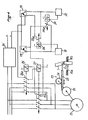
- the seats are moved longitudinally, in one direction or the other, by an electric motor 21 which drives, by means of a torque limiter 22, a mechanism 23 transforming the movement of rotation of the motor in translational movement, this mechanism 23 comprising for example a pinion 24 driven in rotation by the torque limiter 22 and engaged with a longitudinal rack 25, the latter being itself linked to the front foot 1 of the seat by through a connecting slat.
- the electric motor 21 is powered by a switch 26, in the case of forward gear, or a switch 27 in the case of reverse gear.
- the electrical control device further comprises a forward switch 28, a reverse switch 29, a forward delay timer circuit 31, a reverse delay timer circuit 32 and two relays 33,34 respectively connected to the outputs of these two timing circuits.
- a power supply 35 is also provided to supply, from an AC power supply, a direct voltage of +24 volts for example.
- the commons of the two switches 28, 29 are connected to the plus pole of the power supply 35, their rest contacts are connected respectively to the inputs of the two timing circuits 31 and 32, the working contact of the forward switch 28 is connected to on the one hand at the input of the timing circuit 31, via the working contact 34a of the relay 34, and on the other hand at the coil of the forward contactor 26, via a contact of rest 27a of the reverse contactor 27.
- the rest contact of the reverse switch 29 is connected to the input of the timing circuit 32 whose output is connected to relay 34, while the working contact of this switch 29 is connected to the input of the timing circuit 32, via the working contact 33a of the relay 33, and also to the coil of the reverse contactor 27, via the rest contact 26a of the contactor forward 26.
- the operation of the electrical control device as just described is as follows. If we want to move the reference seat which is in the posterior position, that is to say in abutment against the stop 16b, in its anterior position in abutment against the stop 16a, the control button of the switch 28 is acted on to transfer it to the working position. At this time, the forward contactor 26 is energized through the contact 27a which is at rest so that the motor 21 is rotated in forward gear. It then drives, via the torque limiter 22, the pinion 24 which causes a translation of the rack 25 and a movement of the seat forward. This movement of the seat is interrupted when the seat or more particularly its securing members 2 come into contact with the front stop 16a.
- the torque limiter 22 allows the motor 21 to continue to rotate, even when the seat is immobilized against its stop.
- the limiter 22 is designed so as to be able to deliver a sufficient load to move the mobile assembly and not to cause an overload which risks damaging the elements of the system when they are in abutment.
- the working contact 33a then closes, which has the effect of driving the reverse contactor 27 through the contact 26a, returned to rest, of the forward contactor 26.
- the contacts of the contactor 27 which control the supply of the motor 21 are then closed and they remain closed for a certain period of time as a function of the time constant of the timing circuit 31.
- the motor 21 then rotates in the opposite direction, for a short period of time, which has the effect of releasing the stress me in the elements of the pitch variation system, without this resulting in a change in position of the seat in place for manual locking.
- the device according to the invention also applies to the case where the drive motor is of the type supplied by a pressurized fluid (pneumatic or hydraulic cylinder).
- a pressurized fluid pneumatic or hydraulic cylinder.
- the time delay, after the engine has stopped, is ensured by any suitable known fluid circuit.
Landscapes
- Engineering & Computer Science (AREA)
- Aviation & Aerospace Engineering (AREA)
- Transportation (AREA)
- Mechanical Engineering (AREA)
- Seats For Vehicles (AREA)
Applications Claiming Priority (2)
| Application Number | Priority Date | Filing Date | Title |
|---|---|---|---|
| FR8208667A FR2527163A1 (fr) | 1982-05-18 | 1982-05-18 | Dispositif de mise en position des sieges d'un avion commercial equipe d'un dispositif de variation automatique du pas entre les sieges |
| FR8208667 | 1982-05-18 |
Publications (1)
| Publication Number | Publication Date |
|---|---|
| EP0094880A1 true EP0094880A1 (fr) | 1983-11-23 |
Family
ID=9274152
Family Applications (1)
| Application Number | Title | Priority Date | Filing Date |
|---|---|---|---|
| EP83400961A Withdrawn EP0094880A1 (fr) | 1982-05-18 | 1983-05-11 | Dispositif de mise en position des sièges d'un avion commercial équipé d'un dispositif de variation automatique du pas entre les sièges |
Country Status (3)
| Country | Link |
|---|---|
| EP (1) | EP0094880A1 (enExample) |
| JP (1) | JPS5926399A (enExample) |
| FR (1) | FR2527163A1 (enExample) |
Cited By (5)
| Publication number | Priority date | Publication date | Assignee | Title |
|---|---|---|---|---|
| GB2153215A (en) * | 1984-01-04 | 1985-08-21 | Unwin Limited C N | Furniture anchorages |
| EP0282244A1 (en) * | 1987-03-07 | 1988-09-14 | British Aerospace Public Limited Company | Adjusting seating arrangement for aircraft |
| EP0709247A3 (en) * | 1994-10-27 | 1997-09-10 | Unwin C N Ltds | Attachment for vehicle seats |
| DE19736057A1 (de) * | 1997-08-20 | 1999-02-25 | Horst Hartmann | Verfahren zum Zählen von Bewegungen in einem Werkzeug und dessen Anordnung |
| US11136128B2 (en) * | 2016-11-16 | 2021-10-05 | Airbus Operations Gmbh | Aircraft seat kit, and aircraft seat and cabin arrangement with different types of seat rail adapters |
Families Citing this family (4)
| Publication number | Priority date | Publication date | Assignee | Title |
|---|---|---|---|---|
| JPH0328979Y2 (enExample) * | 1986-05-21 | 1991-06-20 | ||
| JPH0630543Y2 (ja) * | 1989-05-17 | 1994-08-17 | アラコ株式会社 | 車両用シートトラック |
| JPH02149323U (enExample) * | 1989-05-22 | 1990-12-19 | ||
| RU2136548C1 (ru) * | 1995-09-14 | 1999-09-10 | АООТ Авиационный научно-технический комплекс им.А.Н.Туполева | Устройство для крепления пассажирского кресла к полу |
Citations (1)
| Publication number | Priority date | Publication date | Assignee | Title |
|---|---|---|---|---|
| EP0021933A1 (fr) * | 1979-06-06 | 1981-01-07 | Tissmetal Lionel-Dupont | Dispositif de variation du pas des sièges dans les avions commerciaux |
-
1982
- 1982-05-18 FR FR8208667A patent/FR2527163A1/fr active Granted
-
1983
- 1983-05-11 EP EP83400961A patent/EP0094880A1/fr not_active Withdrawn
- 1983-05-18 JP JP58087387A patent/JPS5926399A/ja active Pending
Patent Citations (1)
| Publication number | Priority date | Publication date | Assignee | Title |
|---|---|---|---|---|
| EP0021933A1 (fr) * | 1979-06-06 | 1981-01-07 | Tissmetal Lionel-Dupont | Dispositif de variation du pas des sièges dans les avions commerciaux |
Cited By (5)
| Publication number | Priority date | Publication date | Assignee | Title |
|---|---|---|---|---|
| GB2153215A (en) * | 1984-01-04 | 1985-08-21 | Unwin Limited C N | Furniture anchorages |
| EP0282244A1 (en) * | 1987-03-07 | 1988-09-14 | British Aerospace Public Limited Company | Adjusting seating arrangement for aircraft |
| EP0709247A3 (en) * | 1994-10-27 | 1997-09-10 | Unwin C N Ltds | Attachment for vehicle seats |
| DE19736057A1 (de) * | 1997-08-20 | 1999-02-25 | Horst Hartmann | Verfahren zum Zählen von Bewegungen in einem Werkzeug und dessen Anordnung |
| US11136128B2 (en) * | 2016-11-16 | 2021-10-05 | Airbus Operations Gmbh | Aircraft seat kit, and aircraft seat and cabin arrangement with different types of seat rail adapters |
Also Published As
| Publication number | Publication date |
|---|---|
| FR2527163A1 (fr) | 1983-11-25 |
| FR2527163B1 (enExample) | 1985-02-08 |
| JPS5926399A (ja) | 1984-02-10 |
Similar Documents
| Publication | Publication Date | Title |
|---|---|---|
| EP0021933B1 (fr) | Dispositif de variation du pas des sièges dans les avions commerciaux | |
| EP0094880A1 (fr) | Dispositif de mise en position des sièges d'un avion commercial équipé d'un dispositif de variation automatique du pas entre les sièges | |
| FR2716649A1 (fr) | Dispositif de positionnement longitudinal d'un siège de véhicule. | |
| CA2289718C (fr) | Siege tournant, notamment pour vehicule ferroviaire | |
| FR2835790A1 (fr) | Dispositif de calage vertical et automatique d'un siege de vehicule | |
| FR2748054A1 (fr) | Dispositif de verrouillage motorise pour vehicule automobile comportant des moyens perfectionnes de limitation de la course du pene | |
| FR2707935A1 (fr) | Appareil pour l'entraînement d'un siège motorisé de véhicule. | |
| EP0265316A1 (fr) | Système de verrouillage d'un dispositif linéaire de réglage rapide et de blocage d'une pièce mobile par rapport à une pièce fixe | |
| FR2524050A1 (fr) | Systeme de commande de verrouillage pour portieres de vehicules automobiles | |
| EP0723889A1 (fr) | Glissière pour sièges de véhicules | |
| FR2832362A1 (fr) | Mecanisme de reglage pour siege de vehicule automobile et siege equipe d'un tel mecanisme | |
| FR2756522A1 (fr) | Glissiere pour siege de vehicule et siege comportant une telle glissiere | |
| WO1997005396A1 (fr) | Dispositif automatique de guidage indexe d'une piece mobile articulee autour d'un axe sur une piece consideree fixe autour de cet axe | |
| CH635261A5 (fr) | Dispositif de mise en place d'une electrode-fil dans une machine a decouper par etincelage erosif. | |
| FR2473372A1 (fr) | Dispositif de centrage automatique d'une piece dans des machines-outils | |
| CH617539A5 (enExample) | ||
| FR2880597A1 (fr) | Vehicule comportant des sieges sur un plancher a surface plane | |
| FR2662849A1 (fr) | Programmateur electromecanique a preselection douce de programme. | |
| EP0169097A1 (fr) | Glissière à vis, à commande manuelle, électrique ou autre | |
| FR2608492A1 (fr) | Dispositif de glantage pour lentille ophtalmique et appareil de centrage comportant un tel dispositif de glantage | |
| EP3619439B1 (fr) | Dispositif de réglage d'un cable d'actionnement de siège de véhicule automobile | |
| FR2927641A1 (fr) | Mecanisme de deploiement d'une armature, notamment d'une armature de tente, et de maintien de cette armature en position deployee | |
| FR2631076A1 (fr) | Mecanisme de manoeuvre de secours pour les dispositifs de fermeture animes par un moto-reducteur tubulaire a freinage magnetique | |
| EP0102263B1 (fr) | Serrure à commande électrique pour portière de véhicule automobile | |
| FR2481514A1 (fr) | Dispositif de rappel automatique par manque de tension de la commande d'un commutateur rotatif |
Legal Events
| Date | Code | Title | Description |
|---|---|---|---|
| PUAI | Public reference made under article 153(3) epc to a published international application that has entered the european phase |
Free format text: ORIGINAL CODE: 0009012 |
|
| AK | Designated contracting states |
Designated state(s): AT BE CH DE GB IT LI LU NL SE |
|
| STAA | Information on the status of an ep patent application or granted ep patent |
Free format text: STATUS: THE APPLICATION IS DEEMED TO BE WITHDRAWN |
|
| 18D | Application deemed to be withdrawn |
Effective date: 19840724 |
|
| RIN1 | Information on inventor provided before grant (corrected) |
Inventor name: MARTIN, GERARD |