EP0094635A1 - Organe de réglage piézo-électrique - Google Patents
Organe de réglage piézo-électrique Download PDFInfo
- Publication number
- EP0094635A1 EP0094635A1 EP83104715A EP83104715A EP0094635A1 EP 0094635 A1 EP0094635 A1 EP 0094635A1 EP 83104715 A EP83104715 A EP 83104715A EP 83104715 A EP83104715 A EP 83104715A EP 0094635 A1 EP0094635 A1 EP 0094635A1
- Authority
- EP
- European Patent Office
- Prior art keywords
- actuator according
- counter
- pressure plate
- cylinder
- package
- Prior art date
- Legal status (The legal status is an assumption and is not a legal conclusion. Google has not performed a legal analysis and makes no representation as to the accuracy of the status listed.)
- Granted
Links
Images

Classifications
-
- H—ELECTRICITY
- H10—SEMICONDUCTOR DEVICES; ELECTRIC SOLID-STATE DEVICES NOT OTHERWISE PROVIDED FOR
- H10N—ELECTRIC SOLID-STATE DEVICES NOT OTHERWISE PROVIDED FOR
- H10N30/00—Piezoelectric or electrostrictive devices
- H10N30/80—Constructional details
- H10N30/88—Mounts; Supports; Enclosures; Casings
- H10N30/886—Additional mechanical prestressing means, e.g. springs
-
- H—ELECTRICITY
- H10—SEMICONDUCTOR DEVICES; ELECTRIC SOLID-STATE DEVICES NOT OTHERWISE PROVIDED FOR
- H10N—ELECTRIC SOLID-STATE DEVICES NOT OTHERWISE PROVIDED FOR
- H10N30/00—Piezoelectric or electrostrictive devices
- H10N30/50—Piezoelectric or electrostrictive devices having a stacked or multilayer structure
- H10N30/503—Piezoelectric or electrostrictive devices having a stacked or multilayer structure having a non-rectangular cross-section in a plane orthogonal to the stacking direction, e.g. polygonal or circular in top view
- H10N30/505—Piezoelectric or electrostrictive devices having a stacked or multilayer structure having a non-rectangular cross-section in a plane orthogonal to the stacking direction, e.g. polygonal or circular in top view the cross-section being annular
Definitions
- the present invention relates to a piezoelectric actuator according to the preamble of claim 1.
- Such actuators are used in all optics, electron microscopy, micromechanics, in the manufacture of integrated circuits, for precision valves, in ultrasound technology, etc.
- a special application arises in ring laser gyroscopes where such actuators are used in the resonator length regulator or as a dither drive.
- These actuators should have travel ranges up to 100 1 m and actuation forces over 20,000 N. They should be remotely controllable and allow vibration-free mechanical shifts.
- the resolution should be higher than 10 -9 m and the sensitivity better than 10- 10 m.
- Their use in a high vacuum should be possible and they should work without hysteresis and creep. Adjustment speeds are required which are 10 ⁇ m per 10- 3 sec. exceed.
- the use of displacement transducers should be avoided as far as possible; rather, the displacement path should be strictly proportional to the electrical signal applied.
- Piezoelectric actuators that meet all of these requirements are not yet known.
- Piezoelectric 33-stack drives for example, have hitherto been used to generate a high actuating force with a long actuating path.
- the piezoceramic disks are connected to one another by conductive epoxy adhesive and the electrodes consist of metal foils embedded in the adhesive.
- stack drives constructed in this way there is a large additional temperature-dependent shift due to the high thermal expansion of the epoxy adhesive.
- the adhesive properties themselves are strongly temperature-dependent and the adhesive has a mechanical hysteresis due to its partial plasticity. Adhesive also emits gas and is therefore not suitable for use in a high vacuum.
- the actuating path, actuating force, actuating speed, sensitivity and resolution of the actuator are greatly reduced.
- the adhesive layers are also inhomogeneous and can tear with large vibration amplitudes.
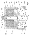
- a stack of piezoceramic disks 10 with electrodes 12 arranged between them is arranged between a base plate 14 and a counter pressure plate 16.
- the piezoceramic disks 10 and the electrodes 12 are provided with central recesses 18.
- the base plate 14 merges into a cylindrical wall 20, which is provided on the outside with a thread 22 and surrounds the piezo stack and the counter pressure plate 16.
- the counter-pressure plate 16 has a tubular extension 24 projecting upwards through the recesses 18.
- a plunger 28 is supported on a shoulder 26 in the tubular extension 24, which protrudes with its lower end 30 over the counter-pressure plate 16 and is rounded off at this end in a spherical shape .
- the plunger 28 also engages with its upper end, which is a Ge wind pin 32 is formed, through a bore 34 in the base plate 14, the base plate in the vicinity of the bore 34 has a greatly reduced thickness dimension.
- a nut 36 pulls the plunger 28 against the shoulder 26 in the tubular extension 24, so that the counter-pressure plate 16 presses the piezo stack 10, 12 against the base plate 14.
- the unit consisting of the pot-shaped housing 14, 20, the counterpressure plate 16 with the tubular extension 24 and the plunger 28 and the piezo stack 10, 12 arranged between them forms an independently manageable unit, the piezo stack being held together by the resilient mechanical prestressing without the use of adhesive becomes.
- the electrodes 12 are vapor-deposited, sputtered or burned onto the piezoceramic disks and are alternately connected to one another via interposed metal foils or special shaping.
- the housing 14, 20 and the plunger 28 are preferably made of a metal with a low coefficient of thermal expansion, e.g. made from Super Invar.
- the counter-pressure plate 16 with the tubular extension 24 is made of the same piezoceramic material as the disks 10, so that a temperature-dependent linear expansion of the piezo stack is compensated for by a corresponding temperature-dependent linear expansion of the tubular extension 24.
- the plunger 28 is supported with its spherical end 30 on a two-part double membrane / cylinder 38.
- This double membrane / cylinder 38 consists of two rotationally symmetrical halves 40 and 42 which are E-shaped in section, the three webs being in optical contact and held together by adhesive forces.
- the connections between the broadened central webs 44, 44 'and the annular outer webs form the ring membranes 48 and 50.
- a dielectric multilayer mirror 52 is applied to the free surface of the lower central web 44'.
- the double membrane / cylinder 38 consists of Zerodur and forms an element which can be displaced in parallel by the stack drive and which is preferably used as a resonator length regulator in ring laser gyroscopes.
- the double diaphragm / cylinder 38 is pulled against the plunger 28 by means of a screw cap 54, which engages with an internal thread in the external thread 22 on the cylindrical housing wall 20 and transfers an annular flange 56 of the upper or lower Zerodurzylinder 40 or 42.
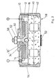
- the pressure actuator according to FIG. 2 differs from that according to FIG. 1 essentially by a piezo stack of smaller overall height and the resultant omission of an exact passive thermal expansion compensation.
- a rough passive thermal expansion compensation is carried out by selecting a suitable metal for the base plate pot 14.
- the counter pressure plate 16 is here with a central, an enlarged bore 34 'in the Base plate 14 protruding threaded pin 58, and in the bottom of the counter-pressure plate 16, a ball 30 'is embedded, which is supported on the double membrane / cylinder 38.
- a tension spring / nut 60 is' adjustable on the threaded pin 58, whereby it is resiliently supported on the base plate 14. If the piezo stack is resiliently biased, the tension spring / nut 60 is fixed in position by a lock nut 62.
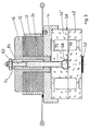
- the base plate 14 and the counter-pressure plate 16 have essentially reversed their position, and a pull rod 64 is arranged which engages with a ball head 66 on the upper half 40 'of the double diaphragm / cylinder 38.
- the upper half 40 'of the zero cylinder is accordingly provided with a recess 68 and a central bore 70.
- the pull rod 64 has a thread in its upper area, with which a threaded sleeve 74 .mu.m supported in the tubular extension 24 adjusts the pretension for the piezo stack.
- the spring is predetermined by the double membrane / cylinder 38.
- the lock nut 62 secures the threaded sleeve 74.
- the piezo stack clamped between the base plate 14 and the counter-pressure plate 16 cannot be handled independently; rather, the double membrane / cylinder 38 is required to resiliently prestress the piezo stack (integrated construction).
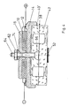
- the train actuators according to FIGS. 4 and 5 again differ essentially from those according to FIG. 3 thanks to a piezo stack with a lower overall height and the resulting elimination of exact passive thermal expansion compensation.
- a suitable metal for the tie rod 64 rough passive thermal expansion compensation is achieved.
- a double-joint support of the pull rod 64 is provided in this exemplary embodiment.
- a hemispherical preload nut 74 is supported in a correspondingly shaped central recess in the counterpressure plate 16 and the thread of the pull rod 64 passes through this preload nut.
- the biasing nut 74 resiliently pulls the counter-pressure plate 16 against the piezo stack, the double membrane / cylinder 38 again specifying the spring force.
- the lock nut 62 secures the hemispherical preload nut 74.
- FIG. 5 shows an embodiment in which the optical contact, even with a tension actuator, is only subjected to pressure is claimed.
- the Zerodur cylinder is provided with a bore 76 diametrically from the side.
- a ball or cylinder nut 78 is inserted into which the tie rod 64 is screwed from above.
- the upper half here consists of a plate 40 'which is rigidly connected to the lower half 42' by optical contact or gold diffusion.
Landscapes
- General Electrical Machinery Utilizing Piezoelectricity, Electrostriction Or Magnetostriction (AREA)
- Micromachines (AREA)
- Mechanical Light Control Or Optical Switches (AREA)
Applications Claiming Priority (2)
| Application Number | Priority Date | Filing Date | Title |
|---|---|---|---|
| DE3218576A DE3218576C2 (de) | 1982-05-17 | 1982-05-17 | Piezoelektrisches Stellglied |
| DE3218576 | 1982-05-17 |
Publications (2)
| Publication Number | Publication Date |
|---|---|
| EP0094635A1 true EP0094635A1 (fr) | 1983-11-23 |
| EP0094635B1 EP0094635B1 (fr) | 1986-11-20 |
Family
ID=6163864
Family Applications (1)
| Application Number | Title | Priority Date | Filing Date |
|---|---|---|---|
| EP83104715A Expired EP0094635B1 (fr) | 1982-05-17 | 1983-05-13 | Organe de réglage piézo-électrique |
Country Status (5)
| Country | Link |
|---|---|
| US (1) | US4488080A (fr) |
| EP (1) | EP0094635B1 (fr) |
| JP (1) | JPS5925286A (fr) |
| CA (1) | CA1210800A (fr) |
| DE (1) | DE3218576C2 (fr) |
Cited By (3)
| Publication number | Priority date | Publication date | Assignee | Title |
|---|---|---|---|---|
| US4969726A (en) * | 1985-06-03 | 1990-11-13 | Northrop Corporation | Ring laser gyro path-length-control mechanism |
| GB2235577A (en) * | 1989-08-28 | 1991-03-06 | Hermsdorf Keramik Veb | Piezoelectric assembly |
| WO2002019441A1 (fr) * | 2000-08-31 | 2002-03-07 | Siemens Aktiengesellschaft | Actionneur piezo-electrique et son procede de production |
Families Citing this family (22)
| Publication number | Priority date | Publication date | Assignee | Title |
|---|---|---|---|---|
| JPS6117762U (ja) * | 1984-07-09 | 1986-02-01 | 日本特殊陶業株式会社 | 電歪駆動体 |
| US4947399A (en) * | 1984-09-04 | 1990-08-07 | Hughes Aircraft Company | Laser mirror displacement device |
| JPH0661447B2 (ja) * | 1985-01-21 | 1994-08-17 | 日立マクセル株式会社 | 真空槽内駆動装置 |
| JPH0436139Y2 (fr) * | 1986-07-18 | 1992-08-26 | ||
| DE3632964A1 (de) * | 1986-09-27 | 1988-04-07 | Physik Instr Pi Gmbh & Co Prod | Piezoelektrisches stellglied |
| US4725753A (en) * | 1986-10-06 | 1988-02-16 | Baker Manufacturing Company | Piezoelectric transducer |
| US4915492A (en) * | 1989-02-06 | 1990-04-10 | Toth Theodor A | Mirror transducer assembly with selected thermal compensation |
| US4933592A (en) * | 1989-03-30 | 1990-06-12 | Priddy Lloyd W | Mirror transducer control circuit |
| JPH03273882A (ja) * | 1990-03-22 | 1991-12-05 | Mitsubishi Electric Corp | 直動駆動装置 |
| US5116128A (en) * | 1990-12-18 | 1992-05-26 | Litton Systems, Inc. | Mirror transducer assembly for ring laser gyroscope |
| US5148076A (en) * | 1991-04-09 | 1992-09-15 | Honeywell Inc. | Apparatus for thermal tuning of path length control drivers |
| US5323228A (en) * | 1991-04-22 | 1994-06-21 | Alliedsignal Inc. | Cavity length controller for ring laser gyroscope applications |
| US5663792A (en) * | 1996-02-09 | 1997-09-02 | Killpatrick; Joseph E. | Transverse mode selected operation for a ring laser |
| DE10028319A1 (de) * | 2000-06-07 | 2001-12-13 | Endress Hauser Gmbh Co | Elektromechanischer Wandler |
| DE10147669A1 (de) * | 2001-09-27 | 2003-04-10 | Bosch Gmbh Robert | Piezoaktor zur Betätigung eines mechanischen Bauteils |
| EP1502310B1 (fr) * | 2002-05-06 | 2008-11-12 | Epcos Ag | Piezoactionneur et son procede de production |
| JP2005124263A (ja) * | 2003-10-14 | 2005-05-12 | Nano Control:Kk | 積層型圧電アクチュエータ用予圧機構および位置決め装置 |
| US7535574B2 (en) * | 2006-09-29 | 2009-05-19 | Honeywell International Inc. | Baseplate for a ring laser gyroscope |
| CN102148325B (zh) * | 2010-12-13 | 2013-05-08 | 吉林大学 | 大负荷压电陶瓷微位移驱动器及其制作方法 |
| JP6300479B2 (ja) * | 2013-09-20 | 2018-03-28 | 日本特殊陶業株式会社 | 圧電素子ユニットおよび圧電アクチュエータ |
| CN111895987B (zh) * | 2020-06-24 | 2022-05-24 | 湖南二零八先进科技有限公司 | 一种减小激光陀螺温变效应的稳频装置 |
| CN115183758B (zh) * | 2022-09-07 | 2022-12-06 | 四川图林科技有限责任公司 | 一种超高精度激光陀螺电磁检抖装置及检测方法 |
Citations (4)
| Publication number | Priority date | Publication date | Assignee | Title |
|---|---|---|---|---|
| US4031418A (en) * | 1974-09-09 | 1977-06-21 | Etat Francais | Low frequency acoustical piezo-electric transducer |
| US4219755A (en) * | 1977-03-18 | 1980-08-26 | Physics International Company | Electromotive actuator |
| EP0017921A1 (fr) * | 1979-04-14 | 1980-10-29 | Discovision Associates | Dispositif d'entraînement piézoélectrique, spécialement pour systèmes de mise au point |
| EP0050712A1 (fr) * | 1980-10-23 | 1982-05-05 | Robert Bosch Gmbh | Elément de réglage mécanique |
Family Cites Families (6)
| Publication number | Priority date | Publication date | Assignee | Title |
|---|---|---|---|---|
| US3461910A (en) * | 1966-06-02 | 1969-08-19 | Gen Dynamics Corp | Hydroacoustic amplifier |
| US3766415A (en) * | 1972-04-18 | 1973-10-16 | R Dame | Piezolectric actuator |
| US4160184A (en) * | 1978-01-09 | 1979-07-03 | The Singer Company | Piezoelectric actuator for a ring laser |
| US4342935A (en) * | 1980-04-10 | 1982-08-03 | Discovision Associates | Binary piezoelectric drive for lens focusing system |
| JPS60362Y2 (ja) * | 1980-06-06 | 1985-01-08 | 近畿イシコ株式会社 | 矢板等の引抜装置 |
| US4384230A (en) * | 1980-11-06 | 1983-05-17 | United Technologies Corporation | Digital piezoelectric actuator |
-
1982
- 1982-05-17 DE DE3218576A patent/DE3218576C2/de not_active Expired
-
1983
- 1983-05-09 US US06/492,980 patent/US4488080A/en not_active Expired - Fee Related
- 1983-05-13 EP EP83104715A patent/EP0094635B1/fr not_active Expired
- 1983-05-16 JP JP58084263A patent/JPS5925286A/ja active Granted
- 1983-05-16 CA CA000428206A patent/CA1210800A/fr not_active Expired
Patent Citations (4)
| Publication number | Priority date | Publication date | Assignee | Title |
|---|---|---|---|---|
| US4031418A (en) * | 1974-09-09 | 1977-06-21 | Etat Francais | Low frequency acoustical piezo-electric transducer |
| US4219755A (en) * | 1977-03-18 | 1980-08-26 | Physics International Company | Electromotive actuator |
| EP0017921A1 (fr) * | 1979-04-14 | 1980-10-29 | Discovision Associates | Dispositif d'entraînement piézoélectrique, spécialement pour systèmes de mise au point |
| EP0050712A1 (fr) * | 1980-10-23 | 1982-05-05 | Robert Bosch Gmbh | Elément de réglage mécanique |
Cited By (5)
| Publication number | Priority date | Publication date | Assignee | Title |
|---|---|---|---|---|
| US4969726A (en) * | 1985-06-03 | 1990-11-13 | Northrop Corporation | Ring laser gyro path-length-control mechanism |
| GB2235577A (en) * | 1989-08-28 | 1991-03-06 | Hermsdorf Keramik Veb | Piezoelectric assembly |
| GB2235577B (en) * | 1989-08-28 | 1993-07-07 | Hermsdorf Keramik Veb | A process for producing an assembly of laminar piezoceramic elements and an assembly produced thereby |
| WO2002019441A1 (fr) * | 2000-08-31 | 2002-03-07 | Siemens Aktiengesellschaft | Actionneur piezo-electrique et son procede de production |
| US6998762B2 (en) | 2000-08-31 | 2006-02-14 | Siemens Aktiengesellschaft | Piezoactuator and a method for producing a piezoactuator |
Also Published As
| Publication number | Publication date |
|---|---|
| JPS5925286A (ja) | 1984-02-09 |
| US4488080A (en) | 1984-12-11 |
| CA1210800A (fr) | 1986-09-02 |
| JPH0324792B2 (fr) | 1991-04-04 |
| EP0094635B1 (fr) | 1986-11-20 |
| DE3218576A1 (de) | 1983-11-24 |
| DE3218576C2 (de) | 1984-11-08 |
Similar Documents
| Publication | Publication Date | Title |
|---|---|---|
| DE3218576C2 (de) | Piezoelektrisches Stellglied | |
| EP0799502B1 (fr) | Element d'entrainement ou de reglage a actionnement piezo-electrique | |
| EP0477400B1 (fr) | Dispositif compensateur de tolérance dans la direction de mouvement du transformateur de déplacement d'un dispositif d'actionnement piézoélectrique | |
| DE102006019942B4 (de) | Kraftmessvorrichtung zur Messung der Kraft bei Festkörperaktoren, Verfahren zur Messung einer Kraft sowie Verwendung der Kraftmessvorrichtung | |
| DE2700342C3 (de) | Piezoelektrischer Meßwandler | |
| DE19928179B4 (de) | Piezoaktor | |
| DE4431478B4 (de) | Aufhängung für mikromechanische Struktur und mikromechanischer Beschleunigungssensor | |
| EP3644009A1 (fr) | Structure de mesure de dilatation dotée d'un support structuré | |
| DE3615930C2 (fr) | ||
| EP0016858A1 (fr) | Elément transducteur piézoélectrique destiné à être monté dans des capteurs de pression, de puissance ou d'accélération | |
| DE19954020A1 (de) | Verfahren zur Herstellung eines piezoelektrischen Wandlers | |
| EP0534270A1 (fr) | Capteur de forces | |
| DE4212077A1 (de) | Piezoelektrisch verstellbares Ventil und Verfahren zu ihrer Herstellung | |
| DE19960971A1 (de) | Piezoaktor | |
| DE19812021A1 (de) | Aktiver Spiegel | |
| DE3622557C2 (fr) | ||
| EP0179278A2 (fr) | Capteur de pression | |
| DE19631026C2 (de) | Verformbare Vorrichtung | |
| DE102010027346A1 (de) | Sensoranordnung | |
| EP3214479B1 (fr) | Dispositif pour deformer un element optique et element optique comporter ce dispositif | |
| EP1941559B1 (fr) | Dispositif de déplacement piézoélectrique | |
| EP2545386B1 (fr) | Accéléromètre comportant un transducteur piézorésistif | |
| DE2812689A1 (de) | Piezoelektrischer druck- bzw. beschleunigungsaufnehmer | |
| DE10023838A1 (de) | Vorrichtung zum Messen einer Wegänderung | |
| DE19547184A1 (de) | Kraftsensor |
Legal Events
| Date | Code | Title | Description |
|---|---|---|---|
| PUAI | Public reference made under article 153(3) epc to a published international application that has entered the european phase |
Free format text: ORIGINAL CODE: 0009012 |
|
| AK | Designated contracting states |
Designated state(s): FR GB IT NL SE |
|
| 17P | Request for examination filed |
Effective date: 19840514 |
|
| GRAA | (expected) grant |
Free format text: ORIGINAL CODE: 0009210 |
|
| RAP1 | Party data changed (applicant data changed or rights of an application transferred) |
Owner name: HONEYWELL REGELSYSTEME GMBH |
|
| AK | Designated contracting states |
Kind code of ref document: B1 Designated state(s): FR GB IT NL SE |
|
| ET | Fr: translation filed | ||
| ITF | It: translation for a ep patent filed | ||
| PLBE | No opposition filed within time limit |
Free format text: ORIGINAL CODE: 0009261 |
|
| STAA | Information on the status of an ep patent application or granted ep patent |
Free format text: STATUS: NO OPPOSITION FILED WITHIN TIME LIMIT |
|
| 26N | No opposition filed | ||
| ITTA | It: last paid annual fee | ||
| PGFP | Annual fee paid to national office [announced via postgrant information from national office to epo] |
Ref country code: FR Payment date: 19940314 Year of fee payment: 12 |
|
| PGFP | Annual fee paid to national office [announced via postgrant information from national office to epo] |
Ref country code: GB Payment date: 19940317 Year of fee payment: 12 |
|
| PGFP | Annual fee paid to national office [announced via postgrant information from national office to epo] |
Ref country code: SE Payment date: 19940318 Year of fee payment: 12 |
|
| PGFP | Annual fee paid to national office [announced via postgrant information from national office to epo] |
Ref country code: NL Payment date: 19940531 Year of fee payment: 12 |
|
| EAL | Se: european patent in force in sweden |
Ref document number: 83104715.4 |
|
| PG25 | Lapsed in a contracting state [announced via postgrant information from national office to epo] |
Ref country code: GB Effective date: 19950513 |
|
| PG25 | Lapsed in a contracting state [announced via postgrant information from national office to epo] |
Ref country code: SE Effective date: 19950514 |
|
| PG25 | Lapsed in a contracting state [announced via postgrant information from national office to epo] |
Ref country code: NL Effective date: 19951201 |
|
| GBPC | Gb: european patent ceased through non-payment of renewal fee |
Effective date: 19950513 |
|
| NLV4 | Nl: lapsed or anulled due to non-payment of the annual fee |
Effective date: 19951201 |
|
| EUG | Se: european patent has lapsed |
Ref document number: 83104715.4 |
|
| PG25 | Lapsed in a contracting state [announced via postgrant information from national office to epo] |
Ref country code: FR Effective date: 19960229 |
|
| REG | Reference to a national code |
Ref country code: FR Ref legal event code: ST |
|
| REG | Reference to a national code |
Ref country code: FR Ref legal event code: ST |