EP0094635A1 - Piezoelectric regulating unit - Google Patents
Piezoelectric regulating unit Download PDFInfo
- Publication number
- EP0094635A1 EP0094635A1 EP83104715A EP83104715A EP0094635A1 EP 0094635 A1 EP0094635 A1 EP 0094635A1 EP 83104715 A EP83104715 A EP 83104715A EP 83104715 A EP83104715 A EP 83104715A EP 0094635 A1 EP0094635 A1 EP 0094635A1
- Authority
- EP
- European Patent Office
- Prior art keywords
- actuator according
- counter
- pressure plate
- cylinder
- package
- Prior art date
- Legal status (The legal status is an assumption and is not a legal conclusion. Google has not performed a legal analysis and makes no representation as to the accuracy of the status listed.)
- Granted
Links
Images

Classifications
-
- H—ELECTRICITY
- H10—SEMICONDUCTOR DEVICES; ELECTRIC SOLID-STATE DEVICES NOT OTHERWISE PROVIDED FOR
- H10N—ELECTRIC SOLID-STATE DEVICES NOT OTHERWISE PROVIDED FOR
- H10N30/00—Piezoelectric or electrostrictive devices
- H10N30/80—Constructional details
- H10N30/88—Mounts; Supports; Enclosures; Casings
- H10N30/886—Additional mechanical prestressing means, e.g. springs
-
- H—ELECTRICITY
- H10—SEMICONDUCTOR DEVICES; ELECTRIC SOLID-STATE DEVICES NOT OTHERWISE PROVIDED FOR
- H10N—ELECTRIC SOLID-STATE DEVICES NOT OTHERWISE PROVIDED FOR
- H10N30/00—Piezoelectric or electrostrictive devices
- H10N30/50—Piezoelectric or electrostrictive devices having a stacked or multilayer structure
- H10N30/503—Piezoelectric or electrostrictive devices having a stacked or multilayer structure having a non-rectangular cross-section in a plane orthogonal to the stacking direction, e.g. polygonal or circular in top view
- H10N30/505—Piezoelectric or electrostrictive devices having a stacked or multilayer structure having a non-rectangular cross-section in a plane orthogonal to the stacking direction, e.g. polygonal or circular in top view the cross-section being annular
Definitions
- the present invention relates to a piezoelectric actuator according to the preamble of claim 1.
- Such actuators are used in all optics, electron microscopy, micromechanics, in the manufacture of integrated circuits, for precision valves, in ultrasound technology, etc.
- a special application arises in ring laser gyroscopes where such actuators are used in the resonator length regulator or as a dither drive.
- These actuators should have travel ranges up to 100 1 m and actuation forces over 20,000 N. They should be remotely controllable and allow vibration-free mechanical shifts.
- the resolution should be higher than 10 -9 m and the sensitivity better than 10- 10 m.
- Their use in a high vacuum should be possible and they should work without hysteresis and creep. Adjustment speeds are required which are 10 ⁇ m per 10- 3 sec. exceed.
- the use of displacement transducers should be avoided as far as possible; rather, the displacement path should be strictly proportional to the electrical signal applied.
- Piezoelectric actuators that meet all of these requirements are not yet known.
- Piezoelectric 33-stack drives for example, have hitherto been used to generate a high actuating force with a long actuating path.
- the piezoceramic disks are connected to one another by conductive epoxy adhesive and the electrodes consist of metal foils embedded in the adhesive.
- stack drives constructed in this way there is a large additional temperature-dependent shift due to the high thermal expansion of the epoxy adhesive.
- the adhesive properties themselves are strongly temperature-dependent and the adhesive has a mechanical hysteresis due to its partial plasticity. Adhesive also emits gas and is therefore not suitable for use in a high vacuum.
- the actuating path, actuating force, actuating speed, sensitivity and resolution of the actuator are greatly reduced.
- the adhesive layers are also inhomogeneous and can tear with large vibration amplitudes.
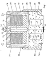
- a stack of piezoceramic disks 10 with electrodes 12 arranged between them is arranged between a base plate 14 and a counter pressure plate 16.
- the piezoceramic disks 10 and the electrodes 12 are provided with central recesses 18.
- the base plate 14 merges into a cylindrical wall 20, which is provided on the outside with a thread 22 and surrounds the piezo stack and the counter pressure plate 16.
- the counter-pressure plate 16 has a tubular extension 24 projecting upwards through the recesses 18.
- a plunger 28 is supported on a shoulder 26 in the tubular extension 24, which protrudes with its lower end 30 over the counter-pressure plate 16 and is rounded off at this end in a spherical shape .
- the plunger 28 also engages with its upper end, which is a Ge wind pin 32 is formed, through a bore 34 in the base plate 14, the base plate in the vicinity of the bore 34 has a greatly reduced thickness dimension.
- a nut 36 pulls the plunger 28 against the shoulder 26 in the tubular extension 24, so that the counter-pressure plate 16 presses the piezo stack 10, 12 against the base plate 14.
- the unit consisting of the pot-shaped housing 14, 20, the counterpressure plate 16 with the tubular extension 24 and the plunger 28 and the piezo stack 10, 12 arranged between them forms an independently manageable unit, the piezo stack being held together by the resilient mechanical prestressing without the use of adhesive becomes.
- the electrodes 12 are vapor-deposited, sputtered or burned onto the piezoceramic disks and are alternately connected to one another via interposed metal foils or special shaping.
- the housing 14, 20 and the plunger 28 are preferably made of a metal with a low coefficient of thermal expansion, e.g. made from Super Invar.
- the counter-pressure plate 16 with the tubular extension 24 is made of the same piezoceramic material as the disks 10, so that a temperature-dependent linear expansion of the piezo stack is compensated for by a corresponding temperature-dependent linear expansion of the tubular extension 24.
- the plunger 28 is supported with its spherical end 30 on a two-part double membrane / cylinder 38.
- This double membrane / cylinder 38 consists of two rotationally symmetrical halves 40 and 42 which are E-shaped in section, the three webs being in optical contact and held together by adhesive forces.
- the connections between the broadened central webs 44, 44 'and the annular outer webs form the ring membranes 48 and 50.
- a dielectric multilayer mirror 52 is applied to the free surface of the lower central web 44'.
- the double membrane / cylinder 38 consists of Zerodur and forms an element which can be displaced in parallel by the stack drive and which is preferably used as a resonator length regulator in ring laser gyroscopes.
- the double diaphragm / cylinder 38 is pulled against the plunger 28 by means of a screw cap 54, which engages with an internal thread in the external thread 22 on the cylindrical housing wall 20 and transfers an annular flange 56 of the upper or lower Zerodurzylinder 40 or 42.
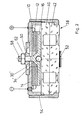
- the pressure actuator according to FIG. 2 differs from that according to FIG. 1 essentially by a piezo stack of smaller overall height and the resultant omission of an exact passive thermal expansion compensation.
- a rough passive thermal expansion compensation is carried out by selecting a suitable metal for the base plate pot 14.
- the counter pressure plate 16 is here with a central, an enlarged bore 34 'in the Base plate 14 protruding threaded pin 58, and in the bottom of the counter-pressure plate 16, a ball 30 'is embedded, which is supported on the double membrane / cylinder 38.
- a tension spring / nut 60 is' adjustable on the threaded pin 58, whereby it is resiliently supported on the base plate 14. If the piezo stack is resiliently biased, the tension spring / nut 60 is fixed in position by a lock nut 62.
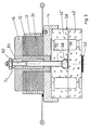
- the base plate 14 and the counter-pressure plate 16 have essentially reversed their position, and a pull rod 64 is arranged which engages with a ball head 66 on the upper half 40 'of the double diaphragm / cylinder 38.
- the upper half 40 'of the zero cylinder is accordingly provided with a recess 68 and a central bore 70.
- the pull rod 64 has a thread in its upper area, with which a threaded sleeve 74 .mu.m supported in the tubular extension 24 adjusts the pretension for the piezo stack.
- the spring is predetermined by the double membrane / cylinder 38.
- the lock nut 62 secures the threaded sleeve 74.
- the piezo stack clamped between the base plate 14 and the counter-pressure plate 16 cannot be handled independently; rather, the double membrane / cylinder 38 is required to resiliently prestress the piezo stack (integrated construction).
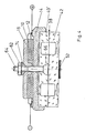
- the train actuators according to FIGS. 4 and 5 again differ essentially from those according to FIG. 3 thanks to a piezo stack with a lower overall height and the resulting elimination of exact passive thermal expansion compensation.
- a suitable metal for the tie rod 64 rough passive thermal expansion compensation is achieved.
- a double-joint support of the pull rod 64 is provided in this exemplary embodiment.
- a hemispherical preload nut 74 is supported in a correspondingly shaped central recess in the counterpressure plate 16 and the thread of the pull rod 64 passes through this preload nut.
- the biasing nut 74 resiliently pulls the counter-pressure plate 16 against the piezo stack, the double membrane / cylinder 38 again specifying the spring force.
- the lock nut 62 secures the hemispherical preload nut 74.
- FIG. 5 shows an embodiment in which the optical contact, even with a tension actuator, is only subjected to pressure is claimed.
- the Zerodur cylinder is provided with a bore 76 diametrically from the side.
- a ball or cylinder nut 78 is inserted into which the tie rod 64 is screwed from above.
- the upper half here consists of a plate 40 'which is rigidly connected to the lower half 42' by optical contact or gold diffusion.
Landscapes
- General Electrical Machinery Utilizing Piezoelectricity, Electrostriction Or Magnetostriction (AREA)
- Mechanical Light Control Or Optical Switches (AREA)
- Micromachines (AREA)
Abstract
Es wird ein piezoelektrisches Stellglied angegeben, das aus einem Paket mit mehreren aufeinandergestapelten piezokeramischen Scheiben (10) und dazwischen angeordneten Elektroden (12) besteht, wobei das Paket lose gestapelt ist und durch ein federndes Element (60) mechanisch vorgespannt und zusammengehalten wird (Figur 2).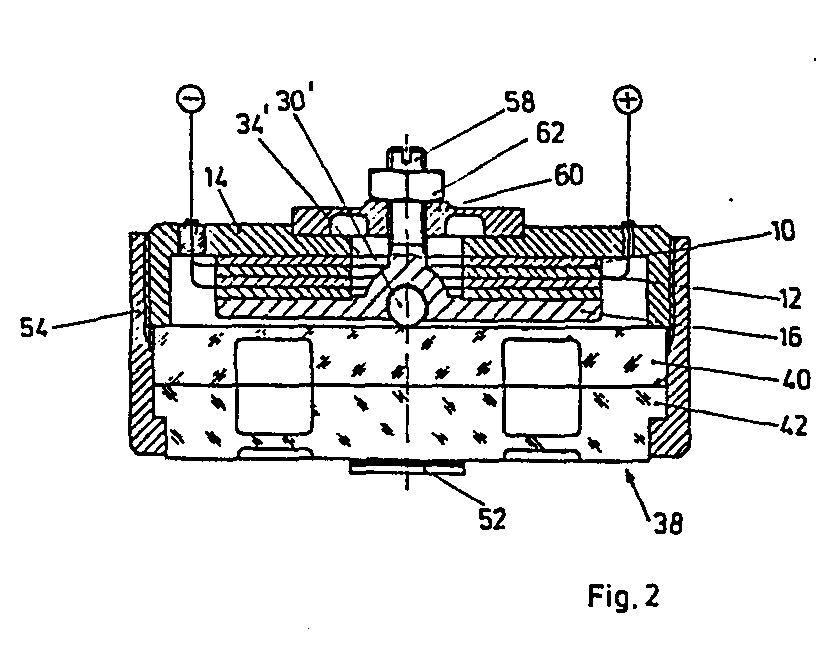
Description
Die vorliegende Erfindung bezieht sich auf ein piezoelektrisches Stellglied nach dem Gattungsbegriff des Anspruches 1. Derartige Stellglieder finden Anwendung in der gesamten Optik, Elektronenmikroskopie, Mikromechanik, bei der Herstellung integrierter Schaltkreise, für Präzisionsventile, in der Ultraschalltechnik usw. Ein besonderer Anwendungsfall ergibt sich bei Ringlaserkreiseln, wo derartige Stellglieder im Resonatorlängenregler oder auch als Ditherantrieb eingesetzt werden. Diese Stellglieder sollen Stellwege bis 1001m und Stellkräfte über 20000 N aufweisen. Sie sollen fernsteuerbar sein und erschütterungsfreie mechanische Verschiebungen gestatten. Hierbei soll die Auflösung höher als 10-9m liegen und die Empfindlichkeit besser als 10-10m sein. Ihre Anwendung in einem Hochvakuum soll möglich sein und sie sollen hysterese- und kriechfrei arbeiten. Stellgeschwindigkeiten werden gefordert, die 10µm pro 10-3sek. überschreiten. Auf die Verwendung von Wegaufnehmern soll möglichst verzichtet werden; vielmehr soll der Verschiebeweg dem angelegten elektrischen Signal streng proportional sein.The present invention relates to a piezoelectric actuator according to the preamble of
Piezoelektrische Stellglieder, die alle diese Forderungen erfüllen, sind bislang nicht bekannt. Zur Erzeugung einer hohen Stellkraft bei großem Stellweg, werden bislang z.B. piezoelektrische 33-Stapelantriebe verwendet. Bei diesen bekannten Stapelantrieben sind die piezokeramischen Scheiben durch leitfähigen Epoxydklebstoff miteinander verbunden und die Elektroden bestehen aus in den Klebstoff eingebetteten Metallfolien. Bei derart aufgebauten Stapelantrieben ergibt sich eine große temperaturabhängige Zusatzverschiebung infolge der hohen Wärmeausdehnung des Epoxydklebstoffs. Ferner sind die Klebstoffeigenschaften selbst stark temperaturabhängig und der Klebstoff besitzt eine mechanische Hysterese infolge seiner teilweisen Plastizität. Klebstoff gast darüberhinaus aus und ist daher nicht für eine Anwendung im Hochvakuum geeignet. Infolge des elastisch-plastischen Verhaltens der Klebstoff-Zwischenschichten in dem Piezostapel werden Stellweg, Stellkraft, Stellgeschwindigkeit, Empfindlichkeit und Auflösung des Stellgliedes stark verringert. Die Klebstoffschichten sind ferner inhomogen und können bei großen Schwingungsamplituden reißen.Piezoelectric actuators that meet all of these requirements are not yet known. Piezoelectric 33-stack drives, for example, have hitherto been used to generate a high actuating force with a long actuating path. With these In known stack drives, the piezoceramic disks are connected to one another by conductive epoxy adhesive and the electrodes consist of metal foils embedded in the adhesive. With stack drives constructed in this way there is a large additional temperature-dependent shift due to the high thermal expansion of the epoxy adhesive. Furthermore, the adhesive properties themselves are strongly temperature-dependent and the adhesive has a mechanical hysteresis due to its partial plasticity. Adhesive also emits gas and is therefore not suitable for use in a high vacuum. As a result of the elastic-plastic behavior of the adhesive intermediate layers in the piezo stack, the actuating path, actuating force, actuating speed, sensitivity and resolution of the actuator are greatly reduced. The adhesive layers are also inhomogeneous and can tear with large vibration amplitudes.
Es ist daher die Aufgabe der vorliegenden Erfindung ein piezoelektrisches Stellglied anzugeben, das bei hoher Stellkraft und großem Stellweg kriech- und hysteresefrei mit hoher Auflösung, Empfindlichkeit und Stellgeschwindigkeit temperaturunabhängig arbeitet und für Anwendungen im Hochvakuum geeignet ist. Die Lösung dieser Aufgabe gelingt gemäß der im Anspruch 1 gekennzeichneten Erfindung. Weitere vorteilhafte Ausgestaltungen der Erfindung sind den Unteransprüchen entnehmbar.It is therefore the object of the present invention to provide a piezoelectric actuator which, with a high actuating force and a large actuating range, works free of creep and hysteresis with high resolution, sensitivity and actuating speed, and is suitable for applications in high vacuum. This object is achieved in accordance with the invention characterized in
Anhand von in den Figuren der beiliegenden Zeichnung dargestellten Ausführungsbeispielen sei im folgenden die Erfindung näher erläutert. Es zeigen:
- Fig.1 ein Druck-Stellglied mit passiver Wärmeausdehnungskompensation für große Stellwege;
- Fig.2 ein Druck-Stellglied gemäß einer weiteren Ausführungsform für kleinere Stellwege und ohne Wärmeausdehnungskompensation;
- Fig.3 ein Zug-Stellglied mit passiver Wärmeausdehnungskompensation für große Stellwege;
- Fig.4 ein Zug-Stellglied gemäß einer weiteren Ausführungsform für kleinere Stellwege und ohne passive Wärmeausdehnungskompensation; und
- Fig.5 ein gegenüber dem Stellglied in Fig.4 weiter modifiziertes Zug-Stellglied.
- 1 shows a pressure actuator with passive Thermal expansion compensation for long travel ranges;
- F ig.2 a pressure actuator according to a further embodiment for smaller travel ranges and without thermal expansion compensation;
- 3 shows a train actuator with passive thermal expansion compensation for long travel ranges;
- 4 shows a train actuator according to a further embodiment for smaller travel ranges and without passive thermal expansion compensation; and
- 5 shows a train actuator further modified compared to the actuator in FIG.
Gemäß Figur 1 ist ein Stapel aus piezokeramischen Scheiben 10 mit dazwischen angeordneten Elektroden 12 zwischen einer Grundplatte 14 und einer Gegendruckplatte 16 angeordnet.According to FIG. 1, a stack of
Die piezokeramischen Scheiben 10 und die Elektroden 12 sind mit zentrischen Ausnehmungen 18 versehen. Die Grundplatte 14 geht in eine zylindrische Wand 20 über, die an der Außenseite mit einem Gewinde 22 versehen ist und den Piezostapel und die Gegendruckplatte 16 umschließt. Die Gegendruckplatte 16 besitzt einen nach oben durch die Ausnehmungen 18 ragenden rohrförmigen Ansatz 24. An einer Schulter 26 in dem rohrförmigen Ansatz 24 stützt sich ein Stößel 28 ab, der mit seinem unteren Ende 30 über die Gegendruckplatte 16 hervorsteht und an diesem Ende kugelförmig abgerundet ist. Der Stößel 28 greift ferner mit seinem oberen Ende,das als Gewindestift 32 ausgebildet ist, durch eine Bohrung 34 in der Grundplatte 14, wobei die Grundplatte in der Umgebung der Bohrung 34 eine stark reduzierte Dickenabmessung aufweist. Eine Mutter 36 zieht den Stößel 28 gegen den Absatz 26 in dem rohrförmigen Ansatz 24, so daß die Gegendruckplatte 16 den Piezostapel 10, 12 gegen die Grundplatte 14 drückt.The
Die Einheit bestehend aus dem topfförmigen Gehäuse 14, 20, der Gegendruckplatte 16 mit dem rohrförmigenAnsatz 24 und dem Stößel 28 und dem dazwischen angeordneten Piezostapel 10, 12 bildet eine selbständig handhabbare Einheit, wobei der Piezostapel ohne die Verwendung von Klebstoff durch die federnde mechanische Vorspannung zusammengehalten wird. Die Elektroden 12 sind auf die piezokeramischen Scheiben aufgedampft, aufgesputtert oder eingebrannt und sind über zwischengelegte Metallfolien oder spezielle Formgebung alternierend miteinander verbunden.The unit consisting of the pot-
Das Gehäuse 14, 20 und der Stößel 28 werden vorzugsweise aus einem Metall mit geringem thermischem Ausdehnungskoeffizienten z.B. aus Super-Invar gefertigt. Hingegen wird die Gegendruckplatte 16 mit dem rohrförmigen Ansatz 24 aus dem gleichen piezokeramischem Material wie die Scheiben 10 gefertigt, so daß eine temperaturabhängige Längenausdehnung des Piezostapels durch eine entsprechende temperaturabhängige -Längenausdehnung des rohrförmigen Ansatzes 24 kompensiert wird.The
Der Stößel 28 stützt sich mit seinem kugelförmigen Ende 30 auf einem zweigeteilten Doppelmembran/Zylinder 38 ab.The
Dieser Doppelmembran/Zylinder 38 besteht aus zwei rotationssymetischen im Schnitt E-förmigen Hälften 40 und 42, wobei sich die drei Stege in optischem Kontakt befinden und durch Adhäsionskräfte zusammengehalten werden. Die Verbindungen zwischen den verbreiterten zentralen Stegen 44, 44' und den ringförmigen Außenstegen bilden die Ringmembranen 48 und 50. Auf der freien Fläche des unteren zentralen Steges 44' ist ein dielektrischer Mehrschichtenspiegel 52 aufgebracht. Der Doppelmembran/Zylinder 38 besteht aus Zerodur und bildet ein durch den Stapelantrieb parallel verschiebbares Element, das vorzugsweise als Resonatorlängenregler bei Ringlaserkreiseln Anwendung findet.This double membrane /
Mittels einer Schraubkappe 54, die mit einem Innengewinde in das Außengewinde 22 an der zylindrischen Gehäusewand 20 eingreift und einen Ringflansch 56 des oberen oder unteren Zerodurzylinders 40 bzw. 42 überstellt, wird der Doppelmembran/Zylinder 38 gegen den Stößel 28 gezogen.The double diaphragm /
Das Druck-Stellglied gemäß Figur 2 unterscheidet sich von demjenigen gemäß Figur 1 im wesentlichen durch einen Piezostapel geringerer Bauhöhe und einem daraus resultierenden Verzicht auf eine exakte passive Wärmeausdehnungskompensation. Eine grobe passive Wärmeausdehnungskompensation erfolgt durch Auswahl eines geeigneten Metalls für den Grundplattentopf 14. Soweit hier und bei den folgenden Ausführungsbeispielen im wesentlichen mit Figur 1 übereinstimmende Bauelemente Anwendung finden, sind diese mit den gleichen Bezugsziffern versehen. In der Funktion übereinstimmende und lediglich konstruktiv modifizierte Bauelemente wurden mit-einem Beistrich versehen.The pressure actuator according to FIG. 2 differs from that according to FIG. 1 essentially by a piezo stack of smaller overall height and the resultant omission of an exact passive thermal expansion compensation. A rough passive thermal expansion compensation is carried out by selecting a suitable metal for the
Abweichend von Figur 1 ist hier die Gegendruckplatte 16 mit einem zentralen, eine vergrößerte Bohrung 34' in der Grundplatte 14 durchragenden Gewindestift 58 versehen, und in den Boden der Gegendruckplatte 16 ist eine Kugel 30' eingelassen, die sich an dem Doppelmembran/Zylinder 38 abstützt. Eine Spannfeder/Mutter 60 ist'auf dem Gewindestift 58 verstellbar, wobei sie sich federnd auf der Grundplatte 14 abstützt. Wenn der Piezostapel entsprechend federnd vorgespannt ist, wird die Spannfeder/Mutter 60 durch eine Kontermutter 62 in ihrer Lage fixiert.Deviating from FIG. 1, the
Bei dem Zug-Stellglied gemäß Figur 3 haben im wesentlichen die Grundplatte 14 und die Gegendruckplatte 16 ihre Lage vertauscht,und es ist eine Zugstange 64 angeordnet, die mit einem Kugelkopf 66 an der oberen Hälfte 40' des Doppelmembran/Zylinders 38 angreift. Die obere Hälfte 40' des Zerodurzylinders ist dementsprechend mit einer Ausnehmung 68 und einer zentralen Bohrung 70 versehen. Die Zugstange 64 weist in ihrem oberen Bereich ein Gewinde auf, mit welchem eine sich in dem rohrförmigen Ansatz 24 abstützende Gewindehülse 74 µm die Vorspannung für den Piezostapel einzustellen. Die Feder ist hierbei durch den Doppelmembran/Zylinder 38 vorgegeben. Die Kontermutter 62 sichert die Gewindehülse 74.In the train actuator according to FIG. 3, the
Im vorliegenden Ausführungsbeispiel ist der zwischen der Grundplatte 14 und der Gegendruckplatte 16 eingespannte Piezostapel nicht selbständig handhabbar; vielmehr bedarf es des Doppelmembran/Zylinders 38,um den Piezostapel federnd vorzuspannen (integrierte Bauweise).In the present exemplary embodiment, the piezo stack clamped between the
Die Zug-Stellglieder gemäß den Figuren4und 5 unterscheiden sich von demjenigen gemäß Figur 3 wiederum im wesentlichen durch einen Piezostapel geringerer Bauhöhe und einen daraus resultierenden Verzicht auf eine exakte passive Wärmeausdehnungskompensation. Durch Auswahl eines geeigneten Metalls für die Zugstange 64 erzielt man eine grobe passive Wärmeausdehnungskompensation. Ferner ist bei diesem Ausführungsbeispiel eine Doppelgelenkabstützung der Zugstange 64 vorgesehen.The train actuators according to FIGS. 4 and 5 again differ essentially from those according to FIG. 3 thanks to a piezo stack with a lower overall height and the resulting elimination of exact passive thermal expansion compensation. By selecting a suitable metal for the
Gemäß Figur 4 stützt sich eine halbkugelförmige Vorspannmutter 74 in einer entsprechend geformten zentralen Ausnehmung in der Gegendruckplatte 16 ab und das Gewinde der Zugstange 64 durchsetzt diese Vorspannmutter. Die Vorspannmutter 74 zieht die Gegendruckplatte 16 federnd gegen den Piezostapel, wobei wiederum der Doppelmembran/Zylinder 38 die Federkraft vorgibt. Die Kontermutter 62 sichert hierbei die halbkugelförmige Vorspannmutter 74.According to FIG. 4, a
Während bei den Ausführungsbeispielen gemäß den Figuren 3 und 4 der optische Kontakt zwischen beiden Hälften 40' und 42 des Doppelmembran/Zylinders 38 auf Zug beansprucht wird, zeigt Figur 5 ein Ausführungsbeispiel, bei dem der optische Kontakt auch bei einem Zug-Stellglied lediglich auf Druck beansprucht wird.3 and 4, the optical contact between the two
Hierzu bedarf es einer Abänderung der unteren Hälfte 42' des Doppelmembran/Zylinders 38 dergestalt, daß der Zerodurzylinder diametral von der Seite mit einer Bohrung 76 versehen wird. In diese Bohrung 76 wird eine Kugel- bzw. Zylindermutter 78 eingesetzt, in die die Zugstange 64 von oben eingeschraubt wird. Die obere Hälfte besteht hier aus einer Platte 40', die durch optischen Kontakt oder Golddiffusion mit der unteren Hälfte 42' starr verbunden ist.This requires a modification of the lower half 42 'of the double membrane /
Claims (17)
Applications Claiming Priority (2)
| Application Number | Priority Date | Filing Date | Title |
|---|---|---|---|
| DE3218576 | 1982-05-17 | ||
| DE3218576A DE3218576C2 (en) | 1982-05-17 | 1982-05-17 | Piezoelectric actuator |
Publications (2)
| Publication Number | Publication Date |
|---|---|
| EP0094635A1 true EP0094635A1 (en) | 1983-11-23 |
| EP0094635B1 EP0094635B1 (en) | 1986-11-20 |
Family
ID=6163864
Family Applications (1)
| Application Number | Title | Priority Date | Filing Date |
|---|---|---|---|
| EP83104715A Expired EP0094635B1 (en) | 1982-05-17 | 1983-05-13 | Piezoelectric regulating unit |
Country Status (5)
| Country | Link |
|---|---|
| US (1) | US4488080A (en) |
| EP (1) | EP0094635B1 (en) |
| JP (1) | JPS5925286A (en) |
| CA (1) | CA1210800A (en) |
| DE (1) | DE3218576C2 (en) |
Cited By (3)
| Publication number | Priority date | Publication date | Assignee | Title |
|---|---|---|---|---|
| US4969726A (en) * | 1985-06-03 | 1990-11-13 | Northrop Corporation | Ring laser gyro path-length-control mechanism |
| GB2235577A (en) * | 1989-08-28 | 1991-03-06 | Hermsdorf Keramik Veb | Piezoelectric assembly |
| WO2002019441A1 (en) * | 2000-08-31 | 2002-03-07 | Siemens Aktiengesellschaft | Piezoactuator and a method for producing a piezoactuator |
Families Citing this family (22)
| Publication number | Priority date | Publication date | Assignee | Title |
|---|---|---|---|---|
| JPS6117762U (en) * | 1984-07-09 | 1986-02-01 | 日本特殊陶業株式会社 | electrostrictive drive body |
| US4947399A (en) * | 1984-09-04 | 1990-08-07 | Hughes Aircraft Company | Laser mirror displacement device |
| JPH0661447B2 (en) * | 1985-01-21 | 1994-08-17 | 日立マクセル株式会社 | Vacuum tank drive |
| JPH0436139Y2 (en) * | 1986-07-18 | 1992-08-26 | ||
| DE3632964A1 (en) * | 1986-09-27 | 1988-04-07 | Physik Instr Pi Gmbh & Co Prod | PIEZOELECTRIC ACTUATOR |
| US4725753A (en) * | 1986-10-06 | 1988-02-16 | Baker Manufacturing Company | Piezoelectric transducer |
| US4915492A (en) * | 1989-02-06 | 1990-04-10 | Toth Theodor A | Mirror transducer assembly with selected thermal compensation |
| US4933592A (en) * | 1989-03-30 | 1990-06-12 | Priddy Lloyd W | Mirror transducer control circuit |
| JPH03273882A (en) * | 1990-03-22 | 1991-12-05 | Mitsubishi Electric Corp | Direct drive device |
| US5116128A (en) * | 1990-12-18 | 1992-05-26 | Litton Systems, Inc. | Mirror transducer assembly for ring laser gyroscope |
| US5148076A (en) * | 1991-04-09 | 1992-09-15 | Honeywell Inc. | Apparatus for thermal tuning of path length control drivers |
| US5323228A (en) * | 1991-04-22 | 1994-06-21 | Alliedsignal Inc. | Cavity length controller for ring laser gyroscope applications |
| US5663792A (en) * | 1996-02-09 | 1997-09-02 | Killpatrick; Joseph E. | Transverse mode selected operation for a ring laser |
| DE10028319A1 (en) * | 2000-06-07 | 2001-12-13 | Endress Hauser Gmbh Co | Electromechanical transducer has piezoelectric elements in stack with intermediate contact electrodes in form of flat connecting vanes fed out of flexible circuit board |
| DE10147669A1 (en) * | 2001-09-27 | 2003-04-10 | Bosch Gmbh Robert | Piezoactuator for operating mechanical part, especially fuel injector, has piezoelement biased by spring element in form of pot and arranged in pot-shaped housing |
| DE50310782D1 (en) * | 2002-05-06 | 2008-12-24 | Epcos Ag | PIEZOACTOR AND METHOD FOR THE PRODUCTION THEREOF |
| JP2005124263A (en) * | 2003-10-14 | 2005-05-12 | Nano Control:Kk | Preloading mechanism and positioning device for multilayer piezoelectric actuator |
| US7535574B2 (en) * | 2006-09-29 | 2009-05-19 | Honeywell International Inc. | Baseplate for a ring laser gyroscope |
| CN102148325B (en) * | 2010-12-13 | 2013-05-08 | 吉林大学 | High-load piezoelectric ceramic micro-displacement actuator and manufacturing method thereof |
| JP6300479B2 (en) * | 2013-09-20 | 2018-03-28 | 日本特殊陶業株式会社 | Piezoelectric element unit and piezoelectric actuator |
| CN111895987B (en) * | 2020-06-24 | 2022-05-24 | 湖南二零八先进科技有限公司 | Frequency stabilizer for reducing temperature variation effect of laser gyroscope |
| CN115183758B (en) * | 2022-09-07 | 2022-12-06 | 四川图林科技有限责任公司 | Electromagnetic jitter detection device and detection method for ultrahigh-precision laser gyroscope |
Citations (4)
| Publication number | Priority date | Publication date | Assignee | Title |
|---|---|---|---|---|
| US4031418A (en) * | 1974-09-09 | 1977-06-21 | Etat Francais | Low frequency acoustical piezo-electric transducer |
| US4219755A (en) * | 1977-03-18 | 1980-08-26 | Physics International Company | Electromotive actuator |
| EP0017921A1 (en) * | 1979-04-14 | 1980-10-29 | Discovision Associates | Piezoelectric-drive system, especially for focussing systems |
| EP0050712A1 (en) * | 1980-10-23 | 1982-05-05 | Robert Bosch Gmbh | Mechanical regulating unit |
Family Cites Families (6)
| Publication number | Priority date | Publication date | Assignee | Title |
|---|---|---|---|---|
| US3461910A (en) * | 1966-06-02 | 1969-08-19 | Gen Dynamics Corp | Hydroacoustic amplifier |
| US3766415A (en) * | 1972-04-18 | 1973-10-16 | R Dame | Piezolectric actuator |
| US4160184A (en) * | 1978-01-09 | 1979-07-03 | The Singer Company | Piezoelectric actuator for a ring laser |
| US4342935A (en) * | 1980-04-10 | 1982-08-03 | Discovision Associates | Binary piezoelectric drive for lens focusing system |
| JPS60362Y2 (en) * | 1980-06-06 | 1985-01-08 | 近畿イシコ株式会社 | Pulling device for sheet piles, etc. |
| US4384230A (en) * | 1980-11-06 | 1983-05-17 | United Technologies Corporation | Digital piezoelectric actuator |
-
1982
- 1982-05-17 DE DE3218576A patent/DE3218576C2/en not_active Expired
-
1983
- 1983-05-09 US US06/492,980 patent/US4488080A/en not_active Expired - Fee Related
- 1983-05-13 EP EP83104715A patent/EP0094635B1/en not_active Expired
- 1983-05-16 JP JP58084263A patent/JPS5925286A/en active Granted
- 1983-05-16 CA CA000428206A patent/CA1210800A/en not_active Expired
Patent Citations (4)
| Publication number | Priority date | Publication date | Assignee | Title |
|---|---|---|---|---|
| US4031418A (en) * | 1974-09-09 | 1977-06-21 | Etat Francais | Low frequency acoustical piezo-electric transducer |
| US4219755A (en) * | 1977-03-18 | 1980-08-26 | Physics International Company | Electromotive actuator |
| EP0017921A1 (en) * | 1979-04-14 | 1980-10-29 | Discovision Associates | Piezoelectric-drive system, especially for focussing systems |
| EP0050712A1 (en) * | 1980-10-23 | 1982-05-05 | Robert Bosch Gmbh | Mechanical regulating unit |
Cited By (5)
| Publication number | Priority date | Publication date | Assignee | Title |
|---|---|---|---|---|
| US4969726A (en) * | 1985-06-03 | 1990-11-13 | Northrop Corporation | Ring laser gyro path-length-control mechanism |
| GB2235577A (en) * | 1989-08-28 | 1991-03-06 | Hermsdorf Keramik Veb | Piezoelectric assembly |
| GB2235577B (en) * | 1989-08-28 | 1993-07-07 | Hermsdorf Keramik Veb | A process for producing an assembly of laminar piezoceramic elements and an assembly produced thereby |
| WO2002019441A1 (en) * | 2000-08-31 | 2002-03-07 | Siemens Aktiengesellschaft | Piezoactuator and a method for producing a piezoactuator |
| US6998762B2 (en) | 2000-08-31 | 2006-02-14 | Siemens Aktiengesellschaft | Piezoactuator and a method for producing a piezoactuator |
Also Published As
| Publication number | Publication date |
|---|---|
| EP0094635B1 (en) | 1986-11-20 |
| JPH0324792B2 (en) | 1991-04-04 |
| US4488080A (en) | 1984-12-11 |
| JPS5925286A (en) | 1984-02-09 |
| DE3218576A1 (en) | 1983-11-24 |
| DE3218576C2 (en) | 1984-11-08 |
| CA1210800A (en) | 1986-09-02 |
Similar Documents
| Publication | Publication Date | Title |
|---|---|---|
| DE3218576C2 (en) | Piezoelectric actuator | |
| EP0477400B1 (en) | Device for compensating the tolerance in the lift direction of the displacement transformer of a piezoelectric actuator | |
| DE102006019942B4 (en) | Force measuring device for measuring the force in solid state actuators, methods for measuring a force and use of the force measuring device | |
| DE2700342C3 (en) | Piezoelectric transducer | |
| DE19928179B4 (en) | piezo actuator | |
| DE4431478B4 (en) | Suspension for micromechanical structure and micromechanical acceleration sensor | |
| DE2948165A1 (en) | CAPACITIVE CONVERTER, ESPECIALLY REACTIVE CONVERTER | |
| DE3615930C2 (en) | ||
| DE112008003151T5 (en) | System and method for biasing piezoelectric actuators | |
| EP0016858A1 (en) | Piezoelectric transducer for mounting in pressure, force or acceleration sensing devices | |
| DE19960971A1 (en) | Piezoactuator e.g. for fuel injector in IC engine, is connected mechanically in series with sensor with stack of interacting piezo elements that produces signal proportional to mechanical displacement | |
| DE19812021A1 (en) | Active mirror | |
| DE102016102469B3 (en) | Optical socket with at least one clamping unit with adhesive gap | |
| DE3622557C2 (en) | ||
| EP0179278A2 (en) | Pressure sensor | |
| EP1527485B1 (en) | Piezoactuator and method for production of the piezoactuator | |
| DE102010027346A1 (en) | sensor arrangement | |
| EP0822602A1 (en) | Device for the deformation of a support by electric or magnetic effects | |
| EP3214479B1 (en) | Apparatus for deforming an optical element and optical element comprising said apparatus | |
| DE10023838C2 (en) | Device for measuring a path change between sections of a component and use of this device | |
| EP1941559B1 (en) | Piezoelectric movement device | |
| EP2545386B1 (en) | Accelerometer comprising a piezoresistive transducer | |
| DE2812689A1 (en) | Small rigid piezoelectric pressure or acceleration sensor - has circular piezoelectric plate with hemisphere and yoke transfer device movable along central axis | |
| DE19547184A1 (en) | Force sensor | |
| DE3218528A1 (en) | Parallel shift device for piezoelectric actuators |
Legal Events
| Date | Code | Title | Description |
|---|---|---|---|
| PUAI | Public reference made under article 153(3) epc to a published international application that has entered the european phase |
Free format text: ORIGINAL CODE: 0009012 |
|
| AK | Designated contracting states |
Designated state(s): FR GB IT NL SE |
|
| 17P | Request for examination filed |
Effective date: 19840514 |
|
| GRAA | (expected) grant |
Free format text: ORIGINAL CODE: 0009210 |
|
| RAP1 | Party data changed (applicant data changed or rights of an application transferred) |
Owner name: HONEYWELL REGELSYSTEME GMBH |
|
| AK | Designated contracting states |
Kind code of ref document: B1 Designated state(s): FR GB IT NL SE |
|
| ET | Fr: translation filed | ||
| ITF | It: translation for a ep patent filed | ||
| PLBE | No opposition filed within time limit |
Free format text: ORIGINAL CODE: 0009261 |
|
| STAA | Information on the status of an ep patent application or granted ep patent |
Free format text: STATUS: NO OPPOSITION FILED WITHIN TIME LIMIT |
|
| 26N | No opposition filed | ||
| ITTA | It: last paid annual fee | ||
| PGFP | Annual fee paid to national office [announced via postgrant information from national office to epo] |
Ref country code: FR Payment date: 19940314 Year of fee payment: 12 |
|
| PGFP | Annual fee paid to national office [announced via postgrant information from national office to epo] |
Ref country code: GB Payment date: 19940317 Year of fee payment: 12 |
|
| PGFP | Annual fee paid to national office [announced via postgrant information from national office to epo] |
Ref country code: SE Payment date: 19940318 Year of fee payment: 12 |
|
| PGFP | Annual fee paid to national office [announced via postgrant information from national office to epo] |
Ref country code: NL Payment date: 19940531 Year of fee payment: 12 |
|
| EAL | Se: european patent in force in sweden |
Ref document number: 83104715.4 |
|
| PG25 | Lapsed in a contracting state [announced via postgrant information from national office to epo] |
Ref country code: GB Effective date: 19950513 |
|
| PG25 | Lapsed in a contracting state [announced via postgrant information from national office to epo] |
Ref country code: SE Effective date: 19950514 |
|
| PG25 | Lapsed in a contracting state [announced via postgrant information from national office to epo] |
Ref country code: NL Effective date: 19951201 |
|
| GBPC | Gb: european patent ceased through non-payment of renewal fee |
Effective date: 19950513 |
|
| NLV4 | Nl: lapsed or anulled due to non-payment of the annual fee |
Effective date: 19951201 |
|
| EUG | Se: european patent has lapsed |
Ref document number: 83104715.4 |
|
| PG25 | Lapsed in a contracting state [announced via postgrant information from national office to epo] |
Ref country code: FR Effective date: 19960229 |
|
| REG | Reference to a national code |
Ref country code: FR Ref legal event code: ST |
|
| REG | Reference to a national code |
Ref country code: FR Ref legal event code: ST |