EP0094220B1 - Abdeckmechanismus zum Verhindern einer Düsenverstopfung bei einem Tintenstrahldrucker - Google Patents
Abdeckmechanismus zum Verhindern einer Düsenverstopfung bei einem Tintenstrahldrucker Download PDFInfo
- Publication number
- EP0094220B1 EP0094220B1 EP83302570A EP83302570A EP0094220B1 EP 0094220 B1 EP0094220 B1 EP 0094220B1 EP 83302570 A EP83302570 A EP 83302570A EP 83302570 A EP83302570 A EP 83302570A EP 0094220 B1 EP0094220 B1 EP 0094220B1
- Authority
- EP
- European Patent Office
- Prior art keywords
- cap member
- stand
- operational
- printer
- shift
- Prior art date
- Legal status (The legal status is an assumption and is not a legal conclusion. Google has not performed a legal analysis and makes no representation as to the accuracy of the status listed.)
- Expired
Links
- 230000000903 blocking effect Effects 0.000 title description 3
- 239000007788 liquid Substances 0.000 description 5
- 238000013016 damping Methods 0.000 description 2
- 239000002904 solvent Substances 0.000 description 2
- 230000000881 depressing effect Effects 0.000 description 1
- 230000000994 depressogenic effect Effects 0.000 description 1
- XLYOFNOQVPJJNP-UHFFFAOYSA-N water Substances O XLYOFNOQVPJJNP-UHFFFAOYSA-N 0.000 description 1
Images

Classifications
-
- B—PERFORMING OPERATIONS; TRANSPORTING
- B41—PRINTING; LINING MACHINES; TYPEWRITERS; STAMPS
- B41J—TYPEWRITERS; SELECTIVE PRINTING MECHANISMS, i.e. MECHANISMS PRINTING OTHERWISE THAN FROM A FORME; CORRECTION OF TYPOGRAPHICAL ERRORS
- B41J2/00—Typewriters or selective printing mechanisms characterised by the printing or marking process for which they are designed
- B41J2/005—Typewriters or selective printing mechanisms characterised by the printing or marking process for which they are designed characterised by bringing liquid or particles selectively into contact with a printing material
- B41J2/01—Ink jet
- B41J2/135—Nozzles
- B41J2/165—Prevention or detection of nozzle clogging, e.g. cleaning, capping or moistening for nozzles
- B41J2/16505—Caps, spittoons or covers for cleaning or preventing drying out
- B41J2/16508—Caps, spittoons or covers for cleaning or preventing drying out connected with the printer frame
- B41J2/16511—Constructions for cap positioning
Definitions
- the present invention relates to a nozzle capping mechanism for an ink jet printer.
- An ink jet printer of the ink-on-demand type includes an orifice which is exposed to the ambience via a nozzle slit.
- a capping mechanism has been proposed to cover the nozzle slit while the ink jet system printer is placed in the non-operating condition.
- the conventional capping mechanism includes a solenoid which makes the system complicated and large.
- German Patent Application No. DE 2746617.A1 describes a nozzle capping mechanism having a cup member which is arranged to be shifted from a non-operational position to an operational position by the drive force applied to shift the print head to a stand-by position. As the print head is moved to the stand-by position it releases a latch and the cap member is urged by a spring into engagement with the print head.
- the mechanism of DE 2746617-A1 employs a solenoid to retract to the cap member when printing recommences.
- the mechanism according to the present invention is characterised in that the cap member is arranged to be shifted from the operational position to the non-operational position by the drive force applied to shift the print head away from the stand-by position.
- the mechanism according to the present invention does not require an energized drive system such as a solenoid.
- the cap member is automatically shifted to and from its operational position by movement of the print head to and away from the stand-by position.
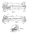
- An ink jet system printer generally includes a platen 2 which is rotatably supported by opposing frames 100 and 101.
- a drive system (not shown) is connected to the platen 2 so as to feed a record receiving paper at a desired time.
- a pair of shafts 3 are disposed between the frames 100 and 101 along the platen 2.
- a carriage 7 is slidably mounted on the pair of shafts 3.
- the carriage 7 is connected to a motor 5 via a wire 11 which is extended between a drum 6 and pulleys 400 and 401. That is, the carriage 7 is driven by the motor 5 to travel along the pair of shafts 3. More specifically, in the actual printing operation, the carriage 7 is driven to reciprocate between a home position 7A and a right margin. Furthermore, the carriage 7 is shifted to a stand-by position 7B when the ink jet system printer is placed in the non-operating condition.
- a printer head 8 is mounted on the carriage 7 so as to confront the platen 2.
- the printer head 8 includes a plurality of orifices and associated nozzle slits for emitting ink droplets toward the record receiving paper which is supported by the platen 2.
- the print information signal is applied from a print control system (not shown) to the carriage 7 (printer head 8) via a cable 9.
- the carriage 7 is driven to shift to the stand-by position 7B and, then, the main power supply is terminated.
- a capping mechanism 10 of the present invention is to cover the nozzle slits when the carriage 7 is located at the stand-by position 7B.
- the capping mechanism 10 includes a cap member 20 mounted on a slidable plate 30.
- the cap member 20 is connected to a reservoir 21, which contains a solvent such as water, via a flexible conduit 22.
- the slidable plate 30 is rotatably mounted on a stationary table 31 through the use of a link 32.
- the cap member 20 includes a vapor chamber 28 having an aperture 23 formed at the front end thereof.
- a damping rubber 26 is secured around the aperture 23 so that the cap member 20 tightly contacts the printer head 8 with the intervention of the damping rubber 26.
- a liquid absorptive sheet 24 is disposed in the vapor chamber 28 in a manner that the liquid absorptive sheet 24 is inclined with respect to the front end of the vapor chamber 28.
- the liquid absorptive sheet 24 is extended to the reservoir 21 through the flexible conduit 22. Therefore, the solvent vapor is filled in the vapor chamber 28 due to the capillarity.
- An opening 29 is formed in the ceiling wall of the vapor chamber 28 in order to prevent the introduction of air into the orifice when the printer head is covered by the cap member 20.
- the ink droplets are emitted from the nozzle under the condition where the printer head is covered by the cap member 20.
- the thus emitted ink droplets are directed to the liquid absorptive sheet 24 and collected to the reservoir 21 via the flexible conduit 22.
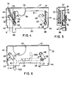
- the slidable plate 30 is shown in Figures 4 and 5.
- the slidable plate 30 includes a cap set projection 65 and a cap reset projection 66 which are projected to the passage of the carriage 7.
- the cap set projection 65 and the cap reset projection 66 are separated from each other by a distance longer than the width of the carriage 7.
- An indent 64 is formed at the rear end of the slidable plate 30, through which the flexible conduit 22 is disposed.
- a guide angle 61 is provided at the rear end of the slidable plate 30, which contacts the surface of the stationary table 31.
- Elliptic openings 62 and 63 are formed in the slidable plate 30 along the side edges of the slidable plate 30, the elliptic openings 62 and 63 accommodating pins 55 and 56 which are provided at the tip ends of the links 32, respectively.
- Springs 70, 71 act between the pins 55 and 56 and the slidable plate 30, so that the slidable plate 30 is urged toward the passage of the carriage 7.
- the links 32 are rotatably supported by shafts 45 and 46 which are disposed on the stationary table 31.
- the shafts 45 and 46 have the same height as the guide angle 61, and the pins 55 and 56 are rotatably engaged in the elliptic openings 62 and 63.
- a spring 72 is disposed between the pin 55 and a side wall 41 of the stationary table 31 so that the slidable plate 30 is pulled backward. That is, the moment in the direction shown by an arrow D is applied by the spring 72 to the link 32, whereby the slidable plate 30 stationary contacts a stopper 44 provided on the stationary table 31 (see Figure 4).
- the stationary table 31 is shown in Figure 6. Side walls 41 and 42 of the stationary table 31 are secured to the body of the ink jet system printer so that the slidable plate 30 supported by the stationary table 31 is disposed along the passage of the carriage 7. An aperture 73 is formed in the stationary table 31, through which the flexible conduit 22 is disposed. A locking leaf spring 49 is secured to the bottom surface of the stationary table 31 through the use of pins 48 in a manner that the leaf spring 49 is parallel to the side wall 41. A locking pin 50 is provided at the tip end of the leaf spring 49. The locking pin 50 protrudes through an aperture 47 formed in the stationary table 31. The link 32 contacts the locking pin 50 to limit the rotation of the link 32 in the direction shown by an arrow E.
- a lock release lever 52 is rotatably secured to the bottom surface of the stationary table 31 by means of a shaft 51. At the tip end of the lock release lever 52, a cam projection 520 is formed. The lock release lever 52 is inserted between the leaf spring 49 and the stationary table 31. The lock release lever 52 has a projection 522 which is projected to the passage of the carriage 7. When a force is applied to the projection 522 in the direction shown by an arrow F, The lock release lever 52 rotates around the shaft 51 so that the cam projection 520 depresses the leaf spring 49 downward to remove the locking pin 50 from the aperture 47.
- the above-mentioned slidable plate 30 and the cap set projection 65 form, in combination, a cap drive means which shifts in the travelling direction of the carriage 7 as the carriage 7 moves to the stand-by position 7B.
- the slidable plate 30, the cap set projection 65 and the links 32 form, in combination, a cap shifting means which pushes the cap member 20 toward the printer head 8 as the carriage 7 moves toward the stand-by position 7B.
- the springs 70 and 71 form, in combination, a first depression means for depressing the cap member 20 to the printer head 8.
- the spring 72 functions as a second spring means for holding the cap member 20 at a position at which the cap member 20 tightly covers the printer head 8.
- the carriage 7 When the main power supply is interrupted, or when the print information signal is not applied to the ink jet system printer for more than a predetermined period of time, the carriage 7 is driven to travel toward the stand-by position 7B.
- the left edge of the carriage 7 depresses the cap set projection 65 and the projection 522 of the lock release lever 52 leftward.
- the slidable plate 30 is depressed leftward to rotate the links 32 around the shafts 45 and 46, respectively, in the direction shown by the arrow E.
- the lock release lever 52 is rotated in the direction shown by the arrow F so that the locking pin 50 is escaped from the locking condition.
- FIG. 7 shows a condition where the slidable plate 30 is located at the capping position.
- the slidable plate 30 is pulled forward by means of the springs 70 and 71, and located as shown by a phantom line H.
- the carriage 7 is held stationary between the projections 65 and 66.
- the cap member 20 mounted on the slidable plate 30 tightly covers the printer head 8 by means of the depression force created by the springs 70 and 71.
- the orifice portion of the printer head 8 contacts the vapor filled in the vapor chamber 28, thereby preventing the blocking of the orifice portion. Even when an inadvertent force is applied to the carriage 7 or the cap member 20, the cap member 20 is returned to the capping position by means of the spring 72.
- the carriage 7 When the print start command is developed, the carriage 7 is driven to shift to the home position 7A. By this movement, the right edge of the carriage 7 depresses the cap reset projection 66 to rotate the links 32 in the direction shown by the arrow D in Figure 4. Thus, the slidable plate 30 is returned to a position where the cap member 20 is separated from the printer head 8.
- the leaf spring 49 depresses the locking pin 50 so that the locking pin 50 is placed in the locking position through the aperture 47.
- the un-capping state is maintained by the spring 72 and locked by the locking pin 50 so that the slidable plate 30 is never placed at a position where the slidable plate 30 disturbs the movement of the carriage 7.
Landscapes
- Ink Jet (AREA)
Claims (6)
Applications Claiming Priority (4)
| Application Number | Priority Date | Filing Date | Title |
|---|---|---|---|
| JP76143/82 | 1982-05-06 | ||
| JP7614382A JPS58193156A (ja) | 1982-05-06 | 1982-05-06 | インクジエツトプリンタの目詰り防止装置 |
| JP76144/82 | 1982-05-06 | ||
| JP7614482A JPS58193157A (ja) | 1982-05-06 | 1982-05-06 | インクジエツトプリンタの目詰り防止装置 |
Publications (2)
| Publication Number | Publication Date |
|---|---|
| EP0094220A1 EP0094220A1 (de) | 1983-11-16 |
| EP0094220B1 true EP0094220B1 (de) | 1986-10-01 |
Family
ID=26417293
Family Applications (1)
| Application Number | Title | Priority Date | Filing Date |
|---|---|---|---|
| EP83302570A Expired EP0094220B1 (de) | 1982-05-06 | 1983-05-06 | Abdeckmechanismus zum Verhindern einer Düsenverstopfung bei einem Tintenstrahldrucker |
Country Status (4)
| Country | Link |
|---|---|
| US (1) | US4533927A (de) |
| EP (1) | EP0094220B1 (de) |
| CA (1) | CA1216463A (de) |
| DE (1) | DE3366542D1 (de) |
Families Citing this family (28)
| Publication number | Priority date | Publication date | Assignee | Title |
|---|---|---|---|---|
| US4819012A (en) * | 1983-06-10 | 1989-04-04 | Canon Kabushiki Kaisha | Ink-jet printer with cap means |
| JPS60162655A (ja) * | 1984-02-03 | 1985-08-24 | Nec Corp | インクジエツトプリンタ |
| US4684963A (en) * | 1984-06-08 | 1987-08-04 | Seiko Epson Kabushiki Kaisha | Nozzle cover assembly for an ink-on-demand type ink jet printer |
| DE3432620A1 (de) * | 1984-09-05 | 1986-03-13 | Agfa-Gevaert Ag, 5090 Leverkusen | Deckel fuer die duesen eines unterdrucktintendruckkopfes |
| DE3611333A1 (de) * | 1985-04-05 | 1986-10-16 | Canon K.K., Tokio/Tokyo | Fluessigkeitsstrahl-aufzeichnungsgeraet und in dem geraet verwendete saug-regeneriereinrichtung |
| US4746938A (en) * | 1985-07-11 | 1988-05-24 | Matsushita Electric Industrial Co. Ltd. | Ink jet recording apparatus with head washing device |
| DE3633239A1 (de) * | 1985-10-01 | 1987-04-16 | Canon Kk | Verfahren zum betrieb einer tintenstrahl-aufzeichnungsvorrichtung und tintenstrahl-aufzeichnungsvorrichtung |
| IT1199923B (it) * | 1985-12-23 | 1989-01-05 | Olivetti & Co Spa | Stampante a punti a getto d'inchiostro con testina multipla regolabile |
| IT1195151B (it) * | 1986-09-05 | 1988-10-12 | Olivetti & Co Spa | Apparecchiatura per ripristinare il funzionamento degli ugelli di una testina di stampa a getto d inchiostro e relativo procedimento |
| US4761665A (en) * | 1987-03-02 | 1988-08-02 | Eastman Kodak Company | High speed print/cartridge printer/feeder |
| US4853717A (en) * | 1987-10-23 | 1989-08-01 | Hewlett-Packard Company | Service station for ink-jet printer |
| ES2073447T3 (es) * | 1988-12-21 | 1995-08-16 | Canon Kk | Mecanismo de recuperacion funcional de un aparato para la impresion por chorros de tinta. |
| US5689293A (en) * | 1989-01-23 | 1997-11-18 | Canon Kabushiki Kaisha | Ink jet head capping device |
| US5703632A (en) * | 1989-09-18 | 1997-12-30 | Canon Kabushiki Kaisha | Ink jet head orifice plate mounting arrangement |
| JPH03101953A (ja) * | 1989-09-18 | 1991-04-26 | Canon Inc | インクジェットカートリッジ及び該インクジェットカートリッジを備えたインクジェット記録装置 |
| US5189443A (en) * | 1989-09-18 | 1993-02-23 | Canon Kabushiki Kaisha | Recording head having stress-minimizing construction |
| US5239316A (en) * | 1989-11-09 | 1993-08-24 | Dataproducts Corporation | Head tend media and system for an ink jet printer |
| ATE122611T1 (de) * | 1990-02-13 | 1995-06-15 | Canon Kk | Aufzeichnungsgerät mit tintenstrahlaufzeichnungskopf. |
| DE69127301T2 (de) * | 1990-04-06 | 1998-02-19 | Canon Kk | Tintenstrahldruckkopfeinheit und Tintenstrahldrucker |
| US5260724A (en) * | 1991-01-09 | 1993-11-09 | Seiko Epson Corporation | Capping device for ink jet printer |
| US5117244A (en) * | 1991-09-23 | 1992-05-26 | Xerox Corporation | Nozzle capping device for an ink jet printhead |
| US5343230A (en) * | 1992-11-20 | 1994-08-30 | Xerox Corporation | Electrical interconnect actuation which interacts with cap station articulation |
| JP3322291B2 (ja) * | 1994-08-11 | 2002-09-09 | セイコーエプソン株式会社 | インクジェット記録装置 |
| US5627574A (en) * | 1995-01-04 | 1997-05-06 | Brother International Corporation | Maintenance device in an ink jet printing apparatus |
| US5627573A (en) * | 1995-01-04 | 1997-05-06 | Brother International Corporation | Maintenance device in an ink jet printing apparatus |
| DE19726642C1 (de) | 1997-06-18 | 1998-09-03 | Francotyp Postalia Gmbh | Vorrichtung zur Positionierung eines Tintendruckkopfes und einer Reinigungs- und Dichtvorrichtung |
| US6183060B1 (en) * | 1997-07-18 | 2001-02-06 | Brother Kogyo Kabushiki Kaisha | Ink jet recorder |
| JP4455266B2 (ja) * | 2003-10-30 | 2010-04-21 | キヤノン株式会社 | 画像形成装置 |
Family Cites Families (6)
| Publication number | Priority date | Publication date | Assignee | Title |
|---|---|---|---|---|
| US4045802A (en) * | 1975-07-29 | 1977-08-30 | Ricoh Company, Ltd. | Ink ejection printing apparatus comprising automatically actuated ejection orifice cap |
| JPS52150029A (en) * | 1976-06-07 | 1977-12-13 | Konishiroku Photo Ind Co Ltd | Ink jet recording device |
| AU507405B2 (en) * | 1976-06-07 | 1980-02-14 | Konishiroku Photo Industry Co., Ltd. | Capping nozzle of inkjet recording device |
| DE2746617C2 (de) * | 1977-10-15 | 1984-08-09 | Olympia Werke Ag, 2940 Wilhelmshaven | Vorrichtung zum Abdecken von Düsenflächen eines Tintenschreibkopfes |
| US4228442A (en) * | 1979-01-24 | 1980-10-14 | Ncr Corporation | Means for preventing drying of ink at nozzles of print heads |
| DE3051198C2 (de) * | 1979-10-23 | 1996-11-14 | Canon Kk | Abdeck- und Absaugvorrichtung für Tintenstrahlschreiber |
-
1983
- 1983-05-05 US US06/491,666 patent/US4533927A/en not_active Expired - Lifetime
- 1983-05-06 EP EP83302570A patent/EP0094220B1/de not_active Expired
- 1983-05-06 CA CA000427675A patent/CA1216463A/en not_active Expired
- 1983-05-06 DE DE8383302570T patent/DE3366542D1/de not_active Expired
Also Published As
| Publication number | Publication date |
|---|---|
| CA1216463A (en) | 1987-01-13 |
| EP0094220A1 (de) | 1983-11-16 |
| DE3366542D1 (en) | 1986-11-06 |
| US4533927A (en) | 1985-08-06 |
Similar Documents
| Publication | Publication Date | Title |
|---|---|---|
| US4533927A (en) | Capping mechanism for preventing nozzle blocking in an ink jet system printer | |
| US5627573A (en) | Maintenance device in an ink jet printing apparatus | |
| US4127335A (en) | Impact printer with cartridge print wheel | |
| EP0847866B1 (de) | Tintenzufuhrbehälter für eine Tintenstrahlaufzeichnungseinheit | |
| JPH0425344Y2 (de) | ||
| US5000594A (en) | Printer with carriage-actuated clutch and paper-feed mechanism | |
| US5861903A (en) | Ink feed system | |
| US6705710B2 (en) | Load and feed apparatus for solid ink | |
| EP0720913B1 (de) | Pflegevorrichtung in einem Tintenstrahldrucker | |
| EP0896881A2 (de) | Tintenstrahlaufzeichnungsvorrichtung | |
| JPH0239818Y2 (de) | ||
| EP1078773B1 (de) | Schlitten mit Shutzabdeckung für die elektrischen Verbindungskontakte und Aufzeichnungsgerät | |
| CA1056323A (en) | Tape advance mechanism | |
| GB2135246A (en) | Daisy wheel supporting structure | |
| US4422785A (en) | Ribbon cartridge construction | |
| CA1052721A (en) | Automatic single and repeat function mechanism for typewriters | |
| GB2078616A (en) | Hand held printing device | |
| US4822186A (en) | Carriage mechanism for thermal printer | |
| US5790148A (en) | Insertable printer head cap for an ink jet printer | |
| US3977510A (en) | Automatic function mechanism for typewriters | |
| GB2224976A (en) | Varying nip pressure between paper feeding rollers | |
| JPS58193157A (ja) | インクジエツトプリンタの目詰り防止装置 | |
| JPH06171079A (ja) | インクジェットプリンタ | |
| CA1050464A (en) | Ribbon cartridge for automatic typewriter function | |
| KR860002849Y1 (ko) | 데이지 프린터의 프린트휠 취부장치 |
Legal Events
| Date | Code | Title | Description |
|---|---|---|---|
| PUAI | Public reference made under article 153(3) epc to a published international application that has entered the european phase |
Free format text: ORIGINAL CODE: 0009012 |
|
| AK | Designated contracting states |
Designated state(s): DE GB IT |
|
| 17P | Request for examination filed |
Effective date: 19840220 |
|
| ITF | It: translation for a ep patent filed | ||
| GRAA | (expected) grant |
Free format text: ORIGINAL CODE: 0009210 |
|
| AK | Designated contracting states |
Kind code of ref document: B1 Designated state(s): DE GB IT |
|
| REF | Corresponds to: |
Ref document number: 3366542 Country of ref document: DE Date of ref document: 19861106 |
|
| PLBE | No opposition filed within time limit |
Free format text: ORIGINAL CODE: 0009261 |
|
| STAA | Information on the status of an ep patent application or granted ep patent |
Free format text: STATUS: NO OPPOSITION FILED WITHIN TIME LIMIT |
|
| 26N | No opposition filed | ||
| ITTA | It: last paid annual fee | ||
| REG | Reference to a national code |
Ref country code: GB Ref legal event code: IF02 |
|
| PGFP | Annual fee paid to national office [announced via postgrant information from national office to epo] |
Ref country code: GB Payment date: 20020501 Year of fee payment: 20 |
|
| PGFP | Annual fee paid to national office [announced via postgrant information from national office to epo] |
Ref country code: DE Payment date: 20020516 Year of fee payment: 20 |
|
| PG25 | Lapsed in a contracting state [announced via postgrant information from national office to epo] |
Ref country code: GB Free format text: LAPSE BECAUSE OF EXPIRATION OF PROTECTION Effective date: 20030505 |
|
| REG | Reference to a national code |
Ref country code: GB Ref legal event code: PE20 |