EP0094174A2 - Geschwindigkeitskorrekturgerät zur Anwendung in einer Geschwindigkeitssteuerung - Google Patents
Geschwindigkeitskorrekturgerät zur Anwendung in einer Geschwindigkeitssteuerung Download PDFInfo
- Publication number
- EP0094174A2 EP0094174A2 EP83302380A EP83302380A EP0094174A2 EP 0094174 A2 EP0094174 A2 EP 0094174A2 EP 83302380 A EP83302380 A EP 83302380A EP 83302380 A EP83302380 A EP 83302380A EP 0094174 A2 EP0094174 A2 EP 0094174A2
- Authority
- EP
- European Patent Office
- Prior art keywords
- speed
- machine part
- movable machine
- command value
- speed command
- Prior art date
- Legal status (The legal status is an assumption and is not a legal conclusion. Google has not performed a legal analysis and makes no representation as to the accuracy of the status listed.)
- Granted
Links
Images


Classifications
-
- G—PHYSICS
- G05—CONTROLLING; REGULATING
- G05B—CONTROL OR REGULATING SYSTEMS IN GENERAL; FUNCTIONAL ELEMENTS OF SUCH SYSTEMS; MONITORING OR TESTING ARRANGEMENTS FOR SUCH SYSTEMS OR ELEMENTS
- G05B19/00—Programme-control systems
- G05B19/02—Programme-control systems electric
- G05B19/18—Numerical control [NC], i.e. automatically operating machines, in particular machine tools, e.g. in a manufacturing environment, so as to execute positioning, movement or co-ordinated operations by means of programme data in numerical form
- G05B19/19—Numerical control [NC], i.e. automatically operating machines, in particular machine tools, e.g. in a manufacturing environment, so as to execute positioning, movement or co-ordinated operations by means of programme data in numerical form characterised by positioning or contouring control systems, e.g. to control position from one programmed point to another or to control movement along a programmed continuous path
- G05B19/21—Numerical control [NC], i.e. automatically operating machines, in particular machine tools, e.g. in a manufacturing environment, so as to execute positioning, movement or co-ordinated operations by means of programme data in numerical form characterised by positioning or contouring control systems, e.g. to control position from one programmed point to another or to control movement along a programmed continuous path using an incremental digital measuring device
- G05B19/23—Numerical control [NC], i.e. automatically operating machines, in particular machine tools, e.g. in a manufacturing environment, so as to execute positioning, movement or co-ordinated operations by means of programme data in numerical form characterised by positioning or contouring control systems, e.g. to control position from one programmed point to another or to control movement along a programmed continuous path using an incremental digital measuring device for point-to-point control
- G05B19/231—Numerical control [NC], i.e. automatically operating machines, in particular machine tools, e.g. in a manufacturing environment, so as to execute positioning, movement or co-ordinated operations by means of programme data in numerical form characterised by positioning or contouring control systems, e.g. to control position from one programmed point to another or to control movement along a programmed continuous path using an incremental digital measuring device for point-to-point control the positional error is used to control continuously the servomotor according to its magnitude
- G05B19/232—Numerical control [NC], i.e. automatically operating machines, in particular machine tools, e.g. in a manufacturing environment, so as to execute positioning, movement or co-ordinated operations by means of programme data in numerical form characterised by positioning or contouring control systems, e.g. to control position from one programmed point to another or to control movement along a programmed continuous path using an incremental digital measuring device for point-to-point control the positional error is used to control continuously the servomotor according to its magnitude with speed feedback only
-
- G—PHYSICS
- G05—CONTROLLING; REGULATING
- G05B—CONTROL OR REGULATING SYSTEMS IN GENERAL; FUNCTIONAL ELEMENTS OF SUCH SYSTEMS; MONITORING OR TESTING ARRANGEMENTS FOR SUCH SYSTEMS OR ELEMENTS
- G05B19/00—Programme-control systems
- G05B19/02—Programme-control systems electric
- G05B19/18—Numerical control [NC], i.e. automatically operating machines, in particular machine tools, e.g. in a manufacturing environment, so as to execute positioning, movement or co-ordinated operations by means of programme data in numerical form
- G05B19/416—Numerical control [NC], i.e. automatically operating machines, in particular machine tools, e.g. in a manufacturing environment, so as to execute positioning, movement or co-ordinated operations by means of programme data in numerical form characterised by control of velocity, acceleration or deceleration
-
- G—PHYSICS
- G05—CONTROLLING; REGULATING
- G05B—CONTROL OR REGULATING SYSTEMS IN GENERAL; FUNCTIONAL ELEMENTS OF SUCH SYSTEMS; MONITORING OR TESTING ARRANGEMENTS FOR SUCH SYSTEMS OR ELEMENTS
- G05B2219/00—Program-control systems
- G05B2219/30—Nc systems
- G05B2219/41—Servomotor, servo controller till figures
- G05B2219/41118—Drift-compensation for servo, anti-hunt
Definitions
- the present invention relates to a speed correcting device having for use in a speed command system for an apparatus/a movable machine part driven at a speed corresponding to a speed command value and, more particularly, to a speed correcting device which permits driving of the movable machine part at a speed accurately corresponding to the speed command value.
- a movable machine part is for example, driven at a speed corresponding to a speed command value fed from,/ a tracer controller, numerical controller or the like, but this may be method / defective in that the driving speed of the movable machine part differs from the speed command value under the influence of an offset voltage which occurs in the speed command system owing to a secular change of an element used.
- a speed correcting device for use in a speed command system of an apparatus in which a movable machine part is driven at a speed corresponding to a speed command value, comprising:
- a speed correcting device for use in a speed command system of an apparatus in which a movable machine part is driven at a speed corresponding to a speed command value, comprising:
- the speed command value may be fed from, for example, a numerical controller, tracer controller or the like.
- An embodiment of the present invention may provide a speed correcting device which is free from the above- said defects of the prior art and permits driving of a movable machine part at a speed exactly corresponding to a speed command value.
- An embodiment of the present invention may provide a speed correcting device which automatically brings the moving speed of a movable machine part into a speed command value.
- An embodiment of the present invention may pro- achieve vide a speed correcting device with which one may/ automatic of correction/the moving speed of a movable machine part into agree- the latter ment with a given speed command value even while/ is being yielded at a value other than zero.
- Fig. 1 illustrates in block form an embodiment of the present invention.
- reference numeral 1 indicates an adder; 2 designates a D/A converter; 3 identifies an adder; 4 denotes a speed control unit; 5 represents a motor; 6 shows a speed detector; 7 refers to a position detector; 8 signifies a counter; 9 indicates an arithmetic circuit; and 10 designates a signal generator which yields an output "1" for a certain period of time At when a push button 11 is pressed.
- the adder 1 is supplied with a speed command value V (a digital quantity) from a tracer controller, numerical controller or the like (not shown); the D/A converter 2 applies the output of the adder 1 to the adder 3; and the speed control unit 4 drives the motor 5 on the basis of the output of the adder 3, i. e. a difference between the output of the D/A converter 2 and the detection result by the speed detector 6. Since such operations are already well-known, no detailed description will be given of them.
- V a digital quantity
- the speed correcting operation starts with reducing the speed command value V to zero which is provided to the adder 1.
- the motor 5 is driven at a speed corresponding to the offset voltage in spite of the speed command value V being zero, and pulses corresponding to the amount of movement of a movable machine part (not shown) are applied from the position detector 7 to the counter 8.
- the counter 8 counts the number of pulses which are applied thereto from the position detector 7 when the signal generator 10 yields an output "1" upon depression of the push button 11 by the operator.
- the count value of the counter 8 corresponds to the amount of movement At of the movable machine part in the time At. Accordingly, the amount of movement ⁇ l of the movable machine part in the time interval At can be obtained by depressing the push button 11 of the signal generator 10.
- the arithmetic circuit 9 performs an operation of the following Eq.
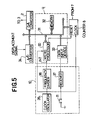
- Fig. 5 is a block diagram illustrating, by way of example, specific arrangements of the counter 8, the arithmetic circuit 9, the signal generator 10 and the adder 1 used in the embodiment of Fig. 1.
- Reference numeral 30 indicates a microprocessor; 31 designates its bus; 32 identifies a memory; 33 denotes a data input device; 34 represents an A/D converter; 35 shows a clock oscillator; 36 refers to a frequency divider; and 37 signifies a receiver.
- the microprocessor 30 is connected via the bus 31 to the memory 32, the A/D converter 34, the D/A converter 2, the counter 8 and the data input device 33.
- the microprocessor 30 operates in synchronism with output pulses of the clock oscillator 35 and sevices an interrupt by the output of the frequency divider 36 which frequency divides the output pulses of the clock oscillator 35.
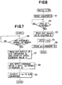
- Fig. 6 is a flowchart explanatory of an operation of the microprocessor 30 for obtaining the moving speed ⁇ v.
- the microprocessor 30 Upon turning ON the switch 11, the microprocessor 30 resets the counter 8 (Sl) and reads out the value of the counter 8 after the time At has elapsed (S2, S3). Then the microprocessor 30 computes ⁇ L/ ⁇ t (S4) and stores the result ⁇ v in the memory 32 (S5).
- Fig. 7 is a flowchart showing an example of an operation of the microprocessor 30 for controlling the speed command for the movable machine part.
- the microprocessor 30 When supplied with an interrupt signal INT from the frequency divider 36, the microprocessor 30 reads out the output of the A/D converter 34 to which is applied a displacement signal of a tracer head in a tracer controller, and computes the speed command value V by a known method (S6, S7) and then adds the computed speed command value V with - ⁇ v stored in the memory 32 (S8). After this, the microprocessor 30 outputs the value V - Av to the D/A converter 2 (S9).
- the same reference numerals are used as those in connection with Figs. 1 and 2, where the components are the same.
- the speed ⁇ v (the actual moving speed of the movable machine part) which is derived from the arithmetic circuit 9 at this time is the sum of the speed command value V and a speed ⁇ v s caused by the offset voltage of the speed command system as indicated by the following Eq. (2):
- the adder 12 obtains the difference between the speed Av output from the arithmetic circuit 9 and the speed command value V as described above, the output Av' of the adder 12 is equal to the speed ⁇ v s caused by the offset voltage. Therefore, the influence of the offset voltage of the speed command system can be removed by adding the output Av' of the adder 12 as an amount of correction to the adder 1, so that the movable machine part can be moved at a speed equal to the speed command value V. Incidentally, the arithmetic circuit 9 continues outputting the speed ⁇ v obtained as described above until the output of the signal generator 10 goes to a "1" again.
- this embodiment is capable of obtaining an amount of correction during application of an arbitrary speed command value, and hence it is simple in operation as compared with the embodiment of Fig. 1 to zero which requires the reduction of the speed command value V/when obtaining the amount of correction.
- the counter 8, the arithmetic circuit 9, the signal generator 10 and the adders 1 and 12 in Fig. 2 can also be realized through utilization of the circuit arrangements depicted in Fig. 5. Also it is possible to compute the moving speed ⁇ v in a similar manner.
- Fig. 8 is a flowchart explanatory of an example of an operation of the microprocessor 30 for controlling the speed command for the movable machine part in the case where the operation of the embodiment of Fig. 2 is placed under the control of the microprocessor 30.
- the microprocessor 30 When supplied with the interrupt signal INT from the frequency divider 36, the microprocessor 30 reads out the output of the A/D converter 34 to which is applied the displacement signal of the tracer head, and computes the speed command value V in a known method (S10, Sll) and then subtracts ⁇ v stored in the memory 32 from the speed command value V to obtain ⁇ v' (S12). After this, the microprocessor 30 adds - ⁇ v' to the speed command value V (S13) and outputs the result to the D/A converter 2 (S14).
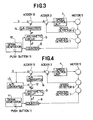
- Fig. 3 illustrates in block form another embodiment of the present invention, which is a modified form of the embodiment of Fig. 1 and in which the speed command value V is provided in an analog form.
- This embodiment differs from the embodiment of Fig. 1 in that the output of the arithmetic circuit 9 is applied via a D/A converter 14 to an adder 13 which carries out an addition of analog quantities. With such an arrangement, it is possible to eliminate the influence of the offset voltage as in the embodiment of Fig. 1 even if the speed command value V is given as an analog quantity.
- the same reference numerals are used as those in connection with Figs. 1 and 3, where the components are the same.
- Fig. 4 illustrates in block form still another embodiment of the present invention, which is a modified form of the embodiment of Fig. 2 and in which the speed command value V is provided in an analog form.
- This embodiment differs from the embodiment of Fig. 2 in that the speed command value V is applied via an A/D converter 15 to the adder 12 and in that the output of the adder 12 is applied via a D/A converter 14 to the adder 13 which performs an addition of analog quantities.
- the speed command value V is applied via an A/D converter 15 to the adder 12 and in that the output of the adder 12 is applied via a D/A converter 14 to the adder 13 which performs an addition of analog quantities.
Landscapes
- Engineering & Computer Science (AREA)
- Human Computer Interaction (AREA)
- Manufacturing & Machinery (AREA)
- Physics & Mathematics (AREA)
- General Physics & Mathematics (AREA)
- Automation & Control Theory (AREA)
- Numerical Control (AREA)
- Control Of Position Or Direction (AREA)
- Control Of Velocity Or Acceleration (AREA)
Applications Claiming Priority (2)
| Application Number | Priority Date | Filing Date | Title |
|---|---|---|---|
| JP57071824A JPS58189706A (ja) | 1982-04-28 | 1982-04-28 | 速度指令系の速度補正方式 |
| JP71824/82 | 1982-04-28 |
Publications (3)
| Publication Number | Publication Date |
|---|---|
| EP0094174A2 true EP0094174A2 (de) | 1983-11-16 |
| EP0094174A3 EP0094174A3 (en) | 1985-11-21 |
| EP0094174B1 EP0094174B1 (de) | 1991-09-04 |
Family
ID=13471682
Family Applications (1)
| Application Number | Title | Priority Date | Filing Date |
|---|---|---|---|
| EP83302380A Expired - Lifetime EP0094174B1 (de) | 1982-04-28 | 1983-04-27 | Geschwindigkeitskorrekturgerät zur Anwendung in einer Geschwindigkeitssteuerung |
Country Status (4)
| Country | Link |
|---|---|
| US (1) | US4622504A (de) |
| EP (1) | EP0094174B1 (de) |
| JP (1) | JPS58189706A (de) |
| DE (1) | DE3382398D1 (de) |
Families Citing this family (9)
| Publication number | Priority date | Publication date | Assignee | Title |
|---|---|---|---|---|
| JPS60211513A (ja) * | 1984-04-06 | 1985-10-23 | Hitachi Ltd | 定常速度誤差補正装置 |
| JPS60250404A (ja) * | 1984-05-25 | 1985-12-11 | Sanesu Shoko:Kk | 数値制御方法 |
| SE8404478L (sv) * | 1984-09-06 | 1985-09-30 | Affarsverket Ffv | Forfarande och anordning vid en regulator for servostyrning av en sjofarkost |
| JPS61125607A (ja) * | 1984-11-23 | 1986-06-13 | Amada Co Ltd | アクチユエ−タの駆動方法及びその装置 |
| JPS62183919A (ja) * | 1986-02-07 | 1987-08-12 | Amada Co Ltd | 板材加工機械のストロ−ク制御方法 |
| JPS6462710A (en) * | 1987-09-02 | 1989-03-09 | Fanuc Ltd | Spindle control system and numerical controller |
| US4918584A (en) * | 1988-07-08 | 1990-04-17 | Performance Controls, Inc. | Self-adjusting servo device and method |
| US5394335A (en) * | 1993-03-31 | 1995-02-28 | Amada Engineering & Service Co., Inc. | Retrofit auto-indexing system |
| JP7117827B2 (ja) * | 2017-05-18 | 2022-08-15 | 川崎重工業株式会社 | モータ制御システム、モータ制御システムの制御方法、及びロボットシステム |
Citations (2)
| Publication number | Priority date | Publication date | Assignee | Title |
|---|---|---|---|---|
| EP0020024A1 (de) * | 1979-04-27 | 1980-12-10 | Nec Corporation | Digital betriebene Servosteuerungsvorrichtung |
| EP0044967A2 (de) * | 1980-07-24 | 1982-02-03 | Maag-Zahnräder und -Maschinen Aktiengesellschaft | Lageregelverfahren und -system für einen Stellzylinderantrieb |
Family Cites Families (9)
| Publication number | Priority date | Publication date | Assignee | Title |
|---|---|---|---|---|
| US3828168A (en) * | 1972-03-31 | 1974-08-06 | Eaton Corp | Controlled velocity drive |
| US3917930A (en) * | 1974-11-25 | 1975-11-04 | Cincinnati Milacron Inc | Method and apparatus for adaptively positioning a machine element |
| JPS51149480A (en) * | 1975-06-16 | 1976-12-22 | Nasuko Kk | Servo device for n umerical control |
| US4139811A (en) * | 1976-10-26 | 1979-02-13 | Xerox Corporation | Method and means for increasing the stiffness of limited frequency servo systems |
| JPS5857762B2 (ja) * | 1977-04-05 | 1983-12-21 | トヨタ自動車株式会社 | ロボットにおける移動速度の修正方法とその装置 |
| JPS5460671A (en) * | 1977-10-21 | 1979-05-16 | Ricoh Co Ltd | Positioning system |
| JPS55131815A (en) * | 1979-04-02 | 1980-10-14 | Nec Corp | Automatic speed correction control system |
| US4368412A (en) * | 1981-02-04 | 1983-01-11 | Inoue-Japax Research Incorporated | Microprocessor-controlled motor drive control system |
| US4486693A (en) * | 1982-07-06 | 1984-12-04 | Contitronix, Inc. | Motor velocity control |
-
1982
- 1982-04-28 JP JP57071824A patent/JPS58189706A/ja active Pending
-
1983
- 1983-04-27 US US06/489,087 patent/US4622504A/en not_active Expired - Fee Related
- 1983-04-27 DE DE8383302380T patent/DE3382398D1/de not_active Expired - Lifetime
- 1983-04-27 EP EP83302380A patent/EP0094174B1/de not_active Expired - Lifetime
Patent Citations (2)
| Publication number | Priority date | Publication date | Assignee | Title |
|---|---|---|---|---|
| EP0020024A1 (de) * | 1979-04-27 | 1980-12-10 | Nec Corporation | Digital betriebene Servosteuerungsvorrichtung |
| EP0044967A2 (de) * | 1980-07-24 | 1982-02-03 | Maag-Zahnräder und -Maschinen Aktiengesellschaft | Lageregelverfahren und -system für einen Stellzylinderantrieb |
Non-Patent Citations (1)
| Title |
|---|
| W.Oppelt "Kleines Handbuch technischer Regelungen" edited in Verlag Chemie, Weinheim (FRG), 1972, pages 13-14; 36 and 695-697 * |
Also Published As
| Publication number | Publication date |
|---|---|
| DE3382398D1 (de) | 1991-10-10 |
| US4622504A (en) | 1986-11-11 |
| JPS58189706A (ja) | 1983-11-05 |
| EP0094174A3 (en) | 1985-11-21 |
| EP0094174B1 (de) | 1991-09-04 |
Similar Documents
| Publication | Publication Date | Title |
|---|---|---|
| US4143310A (en) | Apparatus for positioning | |
| EP0094174A2 (de) | Geschwindigkeitskorrekturgerät zur Anwendung in einer Geschwindigkeitssteuerung | |
| EP0514847B1 (de) | System und Verfahren zur Geschwindigkeitsregelung von elektrischen Motoren in extrem niedrigen Geschwindigkeitsbereichen unter Verwendung eines rotierenden Pulskodierers | |
| US4085890A (en) | Position detecting system | |
| GB2101774A (en) | Motor speed control system | |
| US4128325A (en) | Automatic density measurement calibration for photographic replenishment system | |
| EP0176600B1 (de) | Beschleunigungs-/verlangsamungssystem für numerisch gesteuerte vorrichtung | |
| EP0136827A2 (de) | Kontrollanlage für eine Herstellungs- und Verpackungsvorrichtung von Zigaretten | |
| EP0159109B1 (de) | Apparat zum Ermitteln der Entladungsspalte bei elektroerosiver Bearbeitung | |
| KR880000419B1 (ko) | 수치제어 시스템의 스위치류 장착위치 조정방법 및 장치 | |
| JPS57203108A (en) | Positioning apparatus | |
| US3835360A (en) | Numerical control system | |
| EP0192775B1 (de) | Steuersystem zum betreiben einer fliessbandanlage | |
| EP0649698B1 (de) | Vorrichtung zum elektroerosiven bearbeiten | |
| WO1992009940A1 (en) | Method for executing program for cnc equipment | |
| US5172040A (en) | Numerical control apparatus | |
| EP0841603A1 (de) | Analoge elektronische zeitmessvorrichting | |
| EP0204001A1 (de) | Anordnung zum messen der aufgeschobenen distanz einer numerischen datenvorrichtung | |
| EP0186707B1 (de) | Kopierverfahren | |
| US5115180A (en) | Automatic drift compensation method and device for position-loop controller | |
| JPS6232804B2 (de) | ||
| EP0134029B1 (de) | Drehzahlregelanordnung und Motorregelsystem | |
| EP0374255A1 (de) | Verfahren zur steuerung eines servomotors | |
| JPH0716553B2 (ja) | ミシン制御装置 | |
| JPS6119896Y2 (de) |
Legal Events
| Date | Code | Title | Description |
|---|---|---|---|
| PUAI | Public reference made under article 153(3) epc to a published international application that has entered the european phase |
Free format text: ORIGINAL CODE: 0009012 |
|
| AK | Designated contracting states |
Designated state(s): DE FR GB |
|
| PUAL | Search report despatched |
Free format text: ORIGINAL CODE: 0009013 |
|
| AK | Designated contracting states |
Designated state(s): DE FR GB |
|
| 17P | Request for examination filed |
Effective date: 19851118 |
|
| 17Q | First examination report despatched |
Effective date: 19870804 |
|
| GRAA | (expected) grant |
Free format text: ORIGINAL CODE: 0009210 |
|
| AK | Designated contracting states |
Kind code of ref document: B1 Designated state(s): DE FR GB |
|
| REF | Corresponds to: |
Ref document number: 3382398 Country of ref document: DE Date of ref document: 19911010 |
|
| ET | Fr: translation filed | ||
| PG25 | Lapsed in a contracting state [announced via postgrant information from national office to epo] |
Ref country code: GB Effective date: 19920427 |
|
| PLBE | No opposition filed within time limit |
Free format text: ORIGINAL CODE: 0009261 |
|
| STAA | Information on the status of an ep patent application or granted ep patent |
Free format text: STATUS: NO OPPOSITION FILED WITHIN TIME LIMIT |
|
| 26N | No opposition filed | ||
| GBPC | Gb: european patent ceased through non-payment of renewal fee | ||
| PG25 | Lapsed in a contracting state [announced via postgrant information from national office to epo] |
Ref country code: FR Effective date: 19921230 |
|
| REG | Reference to a national code |
Ref country code: FR Ref legal event code: ST |
|
| PGFP | Annual fee paid to national office [announced via postgrant information from national office to epo] |
Ref country code: DE Payment date: 19930506 Year of fee payment: 11 |
|
| PG25 | Lapsed in a contracting state [announced via postgrant information from national office to epo] |
Ref country code: DE Effective date: 19950103 |