EP0093414A2 - Vacuum switch - Google Patents
Vacuum switch Download PDFInfo
- Publication number
- EP0093414A2 EP0093414A2 EP83104183A EP83104183A EP0093414A2 EP 0093414 A2 EP0093414 A2 EP 0093414A2 EP 83104183 A EP83104183 A EP 83104183A EP 83104183 A EP83104183 A EP 83104183A EP 0093414 A2 EP0093414 A2 EP 0093414A2
- Authority
- EP
- European Patent Office
- Prior art keywords
- flange
- vacuum
- ring
- vacuum interrupter
- elastically
- Prior art date
- Legal status (The legal status is an assumption and is not a legal conclusion. Google has not performed a legal analysis and makes no representation as to the accuracy of the status listed.)
- Granted
Links
Images
Classifications
-
- H—ELECTRICITY
- H01—ELECTRIC ELEMENTS
- H01H—ELECTRIC SWITCHES; RELAYS; SELECTORS; EMERGENCY PROTECTIVE DEVICES
- H01H33/00—High-tension or heavy-current switches with arc-extinguishing or arc-preventing means
- H01H33/60—Switches wherein the means for extinguishing or preventing the arc do not include separate means for obtaining or increasing flow of arc-extinguishing fluid
- H01H33/66—Vacuum switches
- H01H33/662—Housings or protective screens
- H01H33/66207—Specific housing details, e.g. sealing, soldering or brazing
- H01H2033/66215—Details relating to the soldering or brazing of vacuum switch housings
-
- H—ELECTRICITY
- H01—ELECTRIC ELEMENTS
- H01H—ELECTRIC SWITCHES; RELAYS; SELECTORS; EMERGENCY PROTECTIVE DEVICES
- H01H33/00—High-tension or heavy-current switches with arc-extinguishing or arc-preventing means
- H01H33/60—Switches wherein the means for extinguishing or preventing the arc do not include separate means for obtaining or increasing flow of arc-extinguishing fluid
- H01H33/66—Vacuum switches
- H01H33/662—Housings or protective screens
- H01H33/66207—Specific housing details, e.g. sealing, soldering or brazing
- H01H2033/66223—Details relating to the sealing of vacuum switch housings
Definitions
- the invention relates to a vacuum interrupter according to the preamble of claim 1.
- a vacuum interrupter is known from US Pat. No. 3,231,704.
- the elastic ring has a solder flange and an adjacent cylinder jacket.
- the cylinder jacket absorbs different shape changes due to heat fluctuations, while the solder flange follows the changes in the dimensions of the ceramic tube due to its small wall thickness.
- US-PS 3082307 corrugated connection flanges can be found for fastening ceramic tubes to a stud bolt of a vacuum interrupter.
- this patent does not contain any reference to an elastic connection between the stud and the housing.
- the object on which the present invention is based is to increase the inrush current of a vacuum interrupter according to the preamble of claim 1.
- the vacuum interrupter according to the invention is insensitive to longitudinal vibrations and bending vibrations which can occur as a result of a switching operation. It therefore requires considerably less effort to dampen the switch pole vibrations when installed in a circuit breaker.
- the elastically deformable ring is advantageously designed to be flat if the greatest possible mobility in both directions is desired. It can also have the shape of a truncated cone, the smaller surface of which advantageously faces the soldering flange when through the vacuum forces exerted on the flange are to be absorbed by the flange in the form of stresses
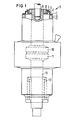
- Fig. 1 shows a switching tube according to the invention in a partially cut and broken view.
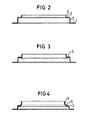
- FIGS. 2 and 3 show two embodiments of a flange according to the invention.
- a switching tube has contacts 10 and 11 which are aligned with one another, of which the fixed contact is fastened to a stud 9.
- an elastic flange 8 is attached via a housing ring 12, which carries a ceramic ring 7 and thus the entire housing of the vacuum interrupter.
- the elastic flange 8 is composed of a solder flange 1, a cylinder wall 2, an elastically easily deformable ring 3 and a cylindrical part 4.
- the solder flange 1 is brazed to the metallized end face 6 of the ceramic tube 7.
- An Agcu eutectic advantageously serves as the solder.
- the cylinder wall 2 is stiff due to its shape when the housing vibrates in or perpendicular to the direction of the housing axis, it does not take part in these vibrations appreciably, a disturbance of its lattice structure by the solder does not affect the life of the tube, even if this means at least in the area , which is adjacent to the solder flange, embrittlement of the material occurs.
- the elastic, easily deformable ring 3 is free from such a disturbance of the lattice structure.
- the adjoining cylindrical Tei1 4 is welded to the housing ring 12. This means that there is no disruption to the lattice structure since, unlike soldering, no foreign metals are fed in during welding will.
- the weld is advantageously carried out only in the forehead area, the remaining, not welded part of the ring also gives a distance from the elastically deformable ring.
- the movable contact 11 is connected to the housing in a vacuum-tight manner via a bolt 13 and a bellows 12.
- the elastically easily deformable ring 3 is flat according to FIG. 2. It therefore ensures a particularly high degree of mobility in the axial directions.
- the elastically easily deformable ring 5 is frustoconical, the smaller cut surface of the truncated cone facing the solder flange 1.
- This embodiment absorbs the compressive force exerted on the housing as a result of the vacuum inside the tube as tensile stress.
- This embodiment enables a particularly thin wall thickness of the flange 8.
- the curved region 6 has an arcuate cross section. This embodiment has proven to be particularly stable and advantageous with the vibrations that occur.
Landscapes
- High-Tension Arc-Extinguishing Switches Without Spraying Means (AREA)
Abstract
In einer Vakuumschaltröhre mit zueinander fluchtenden Kontakten (10, 11), von denen ein Kontakt über einen Stehbolzen (9) als fester Kontakt (10) mit dem Gehäuse mechanisch fest verbunden ist, wird die Verbindung zwischen dem Stehbolzen (9) und dem Gehäuse über einen elastischen Flansch (8) hergestellt, wobei dieser elastische Flansch (8) einen in axialer Richtung elastisch leicht verformbaren Ring (3) enthält, welcher durch eine Zylinderwand (2) von einem Lötflansch (1) getrennt ist. Dadurch wird eine gegenseitige seitliche Verschiebung der Kontakte (10, 11) infolge der beim Stromdurchgang auftretenden mechanischen Kräfte ermöglicht, ohne daß dadurch das kraftschlüssig mit den Kontakten (10, 11) verbundene Gehäuse zerbricht. Die Erfindung eignet sich insbesondere für Vakuumleistungsschaltröhren für sehr hohe Einschaltströme.The connection between the stud (9) and the housing is made in a vacuum interrupter with contacts (10, 11) aligned with one another, of which a contact is mechanically fixed to the housing via a stud (9) as a fixed contact (10) an elastic flange (8) is produced, this elastic flange (8) containing a ring (3) which is easily deformable in the axial direction and which is separated from a soldering flange (1) by a cylinder wall (2). This enables a mutual lateral displacement of the contacts (10, 11) as a result of the mechanical forces which occur during the passage of current, without the housing connected to the contacts (10, 11) thereby being positively broken. The invention is particularly suitable for vacuum interrupters for very high inrush currents.
Description
Die Erfindung betrifft eine Vakuumschaltröhre nach dem Oberbegriff des Patentanspruchs 1. Eine derartige Vakuumschaltröhre ist aus der US-PS 3231 704 bekannt. Dort ist der Flansch über einen elastischen Ring mit dem Keramikrohr des Gehäuses verbunden. Der elastische Ring weist einen Lötflansch und einen daran angrenzenden Zylindermantel auf. Der Zylindermantel fängt unterschiedliche Formveränderungen infolge Wärmeschwankungen auf, während der Lötflansch infolge seiner geringen Wandstärke den Änderungen der Abmessungen des Keramikrohres folgt.The invention relates to a vacuum interrupter according to the preamble of
Der US-PS 3082307 sind gewellte Anschlußflansche zur Befestigung von Keramikrohren an einem Stehbolzen einer Vakuumschaltröhre zu entnehmen. Diese Patentschrift enthält jedoch keinen Hinweis auf eine elastische Verbindung.zwischen dem Stehbolzen und dem Gehäuse.The US-PS 3082307 corrugated connection flanges can be found for fastening ceramic tubes to a stud bolt of a vacuum interrupter. However, this patent does not contain any reference to an elastic connection between the stud and the housing.
Die Aufgabe, die der vorliegenden Erfindung zugrundeliegt, besteht in der Erhöhung der Einschaltstromstärke einer Vakuumschaltröhre gemäß Oberbegriff von Patentanspruch 1.The object on which the present invention is based is to increase the inrush current of a vacuum interrupter according to the preamble of
Diese Aufgabe wird erfindungsgemäß durch die Merkmale des Kennzeichens von Patentanspruch 1 gelöst.This object is achieved by the features of the characterizing part of
Sehr hohe Einschaltströme führten in der Praxis zur Zerstörung des Gehäuses der Röhre. Die Erkenntnis, die unserer Erfindung zugrundeliegt, besteht darin, daß diese Zerstörung des Gehäuses durch eine gegenseitige seitliche Bewegung der beiden Kontakte und durch den damit verbundenen seitlichen Druck auf das Gehäuse hervorgerufen wird. Versuche, die auftretenden Kräfte durch eine
starre Halterung der Kontakte in den entsprechenden Polschuhen abzufangen, führten zu sehr aufwendigen Konstruktionen. Demgegenüber bedeutet die vorliegende Erfindung eine erhebliche Vereinfachung der Konstruktion, die dennoch auch auf lange Sicht die Aufrechterhaltung des Vakuums in der Vakuumschaltröhre gewährleistet. Hierzu mußten gemäß einer Erkenntnis, die dieser Erfindung zugrundeliegt, die Einflüsse des Lotmetalls auf die Eigenschaft des federnden Materials ausgeschaltet werden. Dies wurde durch einen zylinderförmigen Teil erreicht, welcher an den Lötflansch angrenzt und aufgrund seiner Zylinderform und der damit verbundenen hohen Steifigkeit bei Biegebeanspruchungen oder bei Beanspruchungen in axialer Richtung der Schaltröhre nicht nennenswert verformt wird. In diesem Bereich ist eine Störung des Metallgitters und insbesondere eine Versprödung unkritisch. Verformt wird praktisch ausschließlich der elastisch leicht verformbare Ring. An diesen schließt sich ein weiterer zylinderförmiger Teil des Flansches an, welcher mit einem weiteren Gehäuseteil verschweißt werden kann. Bei der SchweiBverbindung entsteht keine schädliche Beeinflussung des Metallgitters, da hierbei kein unterschiedliches Metall in das Metallgitter eingebaut wird. Dementsprechend kann dieser zylinderförmige Teil relativ klein ausgebildet sein.In practice, very high inrush currents led to the destruction of the tube housing. The knowledge on which our invention is based is that this destruction of the housing is caused by a mutual lateral movement of the two contacts and the associated lateral pressure on the housing. Try to use a
rigid mounting of the contacts in the ent Intercepting talking pole pieces led to very complex constructions. In contrast, the present invention means a considerable simplification of the construction, which nevertheless ensures the maintenance of the vacuum in the vacuum interrupter in the long term. For this purpose, according to the knowledge on which this invention is based, the influences of the solder metal on the property of the resilient material had to be eliminated. This was achieved by means of a cylindrical part which adjoins the soldering flange and, due to its cylindrical shape and the associated high rigidity, is not significantly deformed in the event of bending stresses or stresses in the axial direction of the switching tube. In this area, a disturbance in the metal grid and in particular embrittlement is not critical. Only the elastically easily deformable ring is practically deformed. This is followed by a further cylindrical part of the flange, which can be welded to a further housing part. With the welded connection, there is no harmful influence on the metal grid, since no different metal is built into the metal grid. Accordingly, this cylindrical part can be made relatively small.
Die erfindungsgemäße Vakuumschaltröhre ist unempfindlich gegenüber Längsschwingungen und Biegeschwingungen, die infolge eines Schaltvorganges auftreten können. Sie erfordert daher beim Einbau in einen Leistungsschalter einen wesentlich kleineren Aufwand zur Bedämpfung der Schalterpolschwingungen.The vacuum interrupter according to the invention is insensitive to longitudinal vibrations and bending vibrations which can occur as a result of a switching operation. It therefore requires considerably less effort to dampen the switch pole vibrations when installed in a circuit breaker.
Der elastisch verformbare Ring ist vorteilhaft eben ausgestaltet, wenn eine möglichst große Beweglichkeit in beiden Richtungen gewünscht wird. Er kann auch die Form eines Kegelstumpfes aufweisen, dessen kleinere Oberfläche vorteilhaft dem Lötflansch zugewandt ist, wenn die durch das Vakuum auf den Flansch ausgeübten Kräfte in Form von Spannungen durch den Flansch aufgenommen werden sollen.The elastically deformable ring is advantageously designed to be flat if the greatest possible mobility in both directions is desired. It can also have the shape of a truncated cone, the smaller surface of which advantageously faces the soldering flange when through the vacuum forces exerted on the flange are to be absorbed by the flange in the form of stresses
Die Erfindung wird nun anhand von drei Figuren näher erläutert.The invention will now be explained in more detail with reference to three figures.
Fig. 1 zeigt eine erfindungsgemäße Schaltröhre in teilweise geschnittener und gebrochener Ansicht.Fig. 1 shows a switching tube according to the invention in a partially cut and broken view.
Die FigurenThe figures
2 und 3 zeigen zwei Ausführungsformen eines erfindungsgemäßen Flansches.2 and 3 show two embodiments of a flange according to the invention.
Eine Schaltröhre weist zueinander fluchtende Kontakte 10 und 11 auf, von denen der feststehende Kontakt an einem Stehbolzen 9 befestigt ist. An dem Stehbolzen 9 ist über einen Gehäusering 12 ein elastischer Flansch 8 befestigt, welcher einen Keramikring 7 und damit das gesamte Gehäuse der Vakuumschaltröhre trägt.A switching tube has
Der elastische Flansch 8 setzt sich aus einem Lötflansch 1, einer Zylinderwand 2, einem elastisch leicht verformbaren Ring 3 und einem zylindrischen Teil 4 zusammen. Der Lötflansch 1 ist mit der metallisierten Stirnfläche 6 des Keramikrohres 7 hart verlötet. Als Lot dient hierbei vorteilhaft ein Agcu-Eutektikum. Die Zylinderwand 2 ist infolge ihrer Form bei Schwingungen des Gehäuses in oder senkrecht zur Richtung der Gehäuseachse steif, sie nimmt an diesen Schwingungen nicht merklich teil, eine Störung ihres Gittergefüges durch das Lot beeinträchtigt die Lebensdauer der Röhre nicht, auch wenn dadurch zumindest in dem Bereich, der an den Lötflansch angrenzt, eine Versprödung des Materials eintritt. Der elastische,leicht verformbare Ring 3 ist frei von einer derartigen Störung des Gittergefüges. Der daran anschließende zylinderförmige Tei1 4 ist mit dem Gehäusering 12 verschweißt. Dadurch ergibt sich keine Störung des Gittergefüges, da beim Schweißen im Gegensatz zum Löten keine fremden Metalle zugeführt werden. Außerdem erfolgt die Schweißung vorteilhaft nur im Stirnbereich, der verbleibende, nicht verschweißte Teil des Ringes gibt zusätzlich einen Abstand zum elastisch verformbaren Ring.The elastic flange 8 is composed of a
Der bewegliche Kontakt 11 ist über einen Bolzen 13 und einen Balgen 12 mit dem Gehäuse vakuumdicht verbunden.The
Der elastisch leicht verformbare Ring 3 ist gemäß Fig. 2 eben ausgebildet. Er gewährleistet daher eine besonders große Beweglichkeit bei den axialen Richtungen. Gemäß Fig. 3 ist der elastisch leicht verformbare Ring 5 kegelstumpfförmig ausgebildet, wobei die kleinere Schnittfläche des Kegelstumpfes dem Lötflansch 1 zugewandt ist. Diese Ausführungsform nimmt die infolge des im Inneren der Röhre herrschenden Vakuums auf das Gehäuse ausgeübte Druckkraft als Zugspannung auf. Diese Ausführungsform ermöglicht eine besonders dünne Wandstärke des Flansches 8.The elastically easily deformable ring 3 is flat according to FIG. 2. It therefore ensures a particularly high degree of mobility in the axial directions. 3, the elastically easily deformable ring 5 is frustoconical, the smaller cut surface of the truncated cone facing the
Der Übergang vom elastisch leicht verformbaren Ring 3 zum zylinderförmigen Teil 4, der sich an die innere Begrenzung des elastisch leicht verformbaren Ringes 3 anschließt, bildet gemäß Fig. 4 einen stetig gekrümmten Bereich 6, welcher etwa die Hälfte des Abstandes zwischen der Zylinderwand 2 und dem zylinderförmigen Teil 4 erfaßt. Der gekrümmte Bereich 6 hat hierbei einen kreisbogenförmigen Querschnitt. Diese Ausführungsform hat sich als besonders stabil und vorteilhaft bei den auftretenden Schwingungen erwiesen.The transition from the elastically easily deformable ring 3 to the
Claims (6)
Applications Claiming Priority (3)
| Application Number | Priority Date | Filing Date | Title |
|---|---|---|---|
| DE19823216251 DE3216251A1 (en) | 1982-04-30 | 1982-04-30 | VACUUM SWITCH TUBES |
| DE19828212546 DE8212546U1 (en) | 1982-04-30 | 1982-04-30 | Vacuum interrupter |
| DE3216251 | 1982-04-30 |
Publications (3)
| Publication Number | Publication Date |
|---|---|
| EP0093414A2 true EP0093414A2 (en) | 1983-11-09 |
| EP0093414A3 EP0093414A3 (en) | 1985-05-15 |
| EP0093414B1 EP0093414B1 (en) | 1987-09-23 |
Family
ID=25801479
Family Applications (1)
| Application Number | Title | Priority Date | Filing Date |
|---|---|---|---|
| EP83104183A Expired EP0093414B1 (en) | 1982-04-30 | 1983-04-28 | Vacuum switch |
Country Status (4)
| Country | Link |
|---|---|
| US (1) | US4497990A (en) |
| EP (1) | EP0093414B1 (en) |
| JP (1) | JPS58198811A (en) |
| DE (1) | DE3216251A1 (en) |
Cited By (1)
| Publication number | Priority date | Publication date | Assignee | Title |
|---|---|---|---|---|
| DE3803778A1 (en) * | 1988-02-09 | 1989-08-17 | Licentia Gmbh | Vacuum switch with flat or corrugated elastic disc. - used as intermediate piece between fixed-contacts bolt and casings ceramic tube |
Families Citing this family (8)
| Publication number | Priority date | Publication date | Assignee | Title |
|---|---|---|---|---|
| DE3325468A1 (en) * | 1983-07-14 | 1985-01-24 | Siemens AG, 1000 Berlin und 8000 München | HOUSING A VACUUM SWITCH TUBE |
| US4831327A (en) * | 1987-05-01 | 1989-05-16 | Hydro-Quebec | Self-powered electrical measuring system isolated from electrical perturbances |
| DE3825407A1 (en) * | 1988-07-27 | 1990-02-01 | Sachsenwerk Ag | SWITCH CHAMBER OF A VACUUM SWITCH |
| GB2308497A (en) * | 1995-12-21 | 1997-06-25 | Gec Alsthom Ltd | Vacuum switching device |
| US6867385B2 (en) * | 2003-02-21 | 2005-03-15 | Mcgraw-Edison Company | Self-fixturing system for a vacuum interrupter |
| DE102015216911B4 (en) | 2015-09-03 | 2018-10-31 | Siemens Aktiengesellschaft | Vacuum interrupter with a holding element holder and / or a holding element and method for producing such |
| DE102015217403A1 (en) | 2015-09-11 | 2017-03-16 | Siemens Aktiengesellschaft | Switchgear with a vacuum tube |
| DE202017104184U1 (en) | 2017-07-13 | 2018-10-16 | Conductix-Wampfler Gmbh | Device for detecting a state of wear of a sliding contact |
Citations (6)
| Publication number | Priority date | Publication date | Assignee | Title |
|---|---|---|---|---|
| US3082307A (en) * | 1959-04-30 | 1963-03-19 | Gen Electric | Vacuum type circuit interrupter |
| US3231704A (en) * | 1963-04-09 | 1966-01-25 | Jennings Radio Mfg Corp | Hermetically sealed switch with tubular dielectric portions united to a relatively larger metallic intermediate vapor condensing portion |
| GB1026054A (en) * | 1962-05-04 | 1966-04-14 | Ass Elect Ind | Improvements relating to vacuum electric devices |
| US3355564A (en) * | 1966-06-03 | 1967-11-28 | John W Ranheim | Vacuum-type circuit interrupter |
| DE2058020A1 (en) * | 1970-11-25 | 1972-05-31 | Siemens Ag | Vacuum switch housing |
| DE2717562A1 (en) * | 1977-04-20 | 1978-10-26 | Siemens Ag | CONNECTING FLANGE RING FOR VACUUM SWITCHING TUBES |
Family Cites Families (8)
| Publication number | Priority date | Publication date | Assignee | Title |
|---|---|---|---|---|
| NL292339A (en) * | ||||
| NL275722A (en) * | 1961-03-10 | |||
| US3189715A (en) * | 1962-05-21 | 1965-06-15 | Jennings Radio Mfg Corp | Internal shield and seal structure for vacuum sealed switch envelope |
| US3166658A (en) * | 1962-07-05 | 1965-01-19 | Jennings Radio Mfg Corp | Vacuum switch and envelope construction therefor |
| US3196236A (en) * | 1962-07-16 | 1965-07-20 | Jennings Radio Mfg Corp | High power vacuum circuit breaker contacts and arc-extinguishing means therefor |
| US3261953A (en) * | 1963-10-10 | 1966-07-19 | Jennings Radio Mfg Corp | High power rf relay incorporating heatsink and fluid cooling |
| JPS5636011Y2 (en) * | 1979-08-30 | 1981-08-25 | ||
| JPS56156626A (en) * | 1980-05-06 | 1981-12-03 | Meidensha Electric Mfg Co Ltd | Vacuum breaker |
-
1982
- 1982-04-30 DE DE19823216251 patent/DE3216251A1/en not_active Ceased
-
1983
- 1983-04-25 US US06/488,187 patent/US4497990A/en not_active Expired - Fee Related
- 1983-04-28 EP EP83104183A patent/EP0093414B1/en not_active Expired
- 1983-04-28 JP JP58076041A patent/JPS58198811A/en active Pending
Patent Citations (6)
| Publication number | Priority date | Publication date | Assignee | Title |
|---|---|---|---|---|
| US3082307A (en) * | 1959-04-30 | 1963-03-19 | Gen Electric | Vacuum type circuit interrupter |
| GB1026054A (en) * | 1962-05-04 | 1966-04-14 | Ass Elect Ind | Improvements relating to vacuum electric devices |
| US3231704A (en) * | 1963-04-09 | 1966-01-25 | Jennings Radio Mfg Corp | Hermetically sealed switch with tubular dielectric portions united to a relatively larger metallic intermediate vapor condensing portion |
| US3355564A (en) * | 1966-06-03 | 1967-11-28 | John W Ranheim | Vacuum-type circuit interrupter |
| DE2058020A1 (en) * | 1970-11-25 | 1972-05-31 | Siemens Ag | Vacuum switch housing |
| DE2717562A1 (en) * | 1977-04-20 | 1978-10-26 | Siemens Ag | CONNECTING FLANGE RING FOR VACUUM SWITCHING TUBES |
Cited By (1)
| Publication number | Priority date | Publication date | Assignee | Title |
|---|---|---|---|---|
| DE3803778A1 (en) * | 1988-02-09 | 1989-08-17 | Licentia Gmbh | Vacuum switch with flat or corrugated elastic disc. - used as intermediate piece between fixed-contacts bolt and casings ceramic tube |
Also Published As
| Publication number | Publication date |
|---|---|
| US4497990A (en) | 1985-02-05 |
| EP0093414B1 (en) | 1987-09-23 |
| DE3216251A1 (en) | 1983-11-03 |
| JPS58198811A (en) | 1983-11-18 |
| EP0093414A3 (en) | 1985-05-15 |
Similar Documents
| Publication | Publication Date | Title |
|---|---|---|
| CH616269A5 (en) | ||
| DE602005001955T2 (en) | Fastening device for a protective screen in an electrical switch, in particular a vacuum switch. | |
| EP0093414A2 (en) | Vacuum switch | |
| DE9305074U1 (en) | Microswitch | |
| EP0352611B1 (en) | Chamber of a vacuum interrupter switching | |
| EP0149061A1 (en) | Vacuum switch for low tension, particularly a low tension protector | |
| DE10029763B4 (en) | Vacuum interrupter | |
| EP0335114B1 (en) | Housing for a vacuum switch | |
| EP0132804B1 (en) | Vacuum switch, particularly for a low-voltage protector | |
| DE3319010C2 (en) | ||
| EP0568166B1 (en) | Vacuum switch tube | |
| DE1765920B2 (en) | Contact arrangement for electrical switching devices | |
| DE3344643A1 (en) | Vacuum switching tube for medium-voltage switching apparatuses | |
| DE8212546U1 (en) | Vacuum interrupter | |
| EP0354445B1 (en) | Arc chamber for a vacuum switch | |
| DE3803778A1 (en) | Vacuum switch with flat or corrugated elastic disc. - used as intermediate piece between fixed-contacts bolt and casings ceramic tube | |
| DE3883802T2 (en) | Lightning rod. | |
| DE2725092A1 (en) | LV vacuum contactor system - is mounted inside insulating tube with cover at one end and springy, movable closure for movable contact at other end | |
| DE19713478C1 (en) | Vacuum switch tube e.g. for low-voltage switching | |
| DE102008049995B3 (en) | Vacuum interrupter | |
| DE3144029C2 (en) | ||
| DE102008037112B4 (en) | Vacuum interrupter | |
| EP0289447B1 (en) | Cutting device for high current rails | |
| DE2065920C3 (en) | Magnetically operated electrical switch with at least one flexible, magnetically permeable switch tongue | |
| DE4020820C2 (en) | Short circuit arrangement for high current |
Legal Events
| Date | Code | Title | Description |
|---|---|---|---|
| PUAI | Public reference made under article 153(3) epc to a published international application that has entered the european phase |
Free format text: ORIGINAL CODE: 0009012 |
|
| AK | Designated contracting states |
Designated state(s): CH FR GB LI SE |
|
| PUAL | Search report despatched |
Free format text: ORIGINAL CODE: 0009013 |
|
| AK | Designated contracting states |
Designated state(s): CH FR GB LI SE |
|
| 17P | Request for examination filed |
Effective date: 19850404 |
|
| GRAA | (expected) grant |
Free format text: ORIGINAL CODE: 0009210 |
|
| AK | Designated contracting states |
Kind code of ref document: B1 Designated state(s): CH FR GB LI SE |
|
| ET | Fr: translation filed | ||
| GBT | Gb: translation of ep patent filed (gb section 77(6)(a)/1977) | ||
| PLBI | Opposition filed |
Free format text: ORIGINAL CODE: 0009260 |
|
| 26 | Opposition filed |
Opponent name: AEG AKTIENGESELLSCHAFT, BERLIN UND FRANKFURT Effective date: 19880610 |
|
| PGFP | Annual fee paid to national office [announced via postgrant information from national office to epo] |
Ref country code: GB Payment date: 19900331 Year of fee payment: 8 |
|
| PGFP | Annual fee paid to national office [announced via postgrant information from national office to epo] |
Ref country code: SE Payment date: 19900425 Year of fee payment: 8 |
|
| PGFP | Annual fee paid to national office [announced via postgrant information from national office to epo] |
Ref country code: FR Payment date: 19900427 Year of fee payment: 8 |
|
| PGFP | Annual fee paid to national office [announced via postgrant information from national office to epo] |
Ref country code: CH Payment date: 19900724 Year of fee payment: 8 |
|
| RDAG | Patent revoked |
Free format text: ORIGINAL CODE: 0009271 |
|
| STAA | Information on the status of an ep patent application or granted ep patent |
Free format text: STATUS: PATENT REVOKED |
|
| 27W | Patent revoked |
Effective date: 19901217 |
|
| GBPR | Gb: patent revoked under art. 102 of the ep convention designating the uk as contracting state | ||
| REG | Reference to a national code |
Ref country code: CH Ref legal event code: PL |
|
| EUG | Se: european patent has lapsed |
Ref document number: 83104183.5 Effective date: 19910313 |
|
| APAH | Appeal reference modified |
Free format text: ORIGINAL CODE: EPIDOSCREFNO |