EP0093005B1 - Laser device - Google Patents
Laser device Download PDFInfo
- Publication number
- EP0093005B1 EP0093005B1 EP19830302327 EP83302327A EP0093005B1 EP 0093005 B1 EP0093005 B1 EP 0093005B1 EP 19830302327 EP19830302327 EP 19830302327 EP 83302327 A EP83302327 A EP 83302327A EP 0093005 B1 EP0093005 B1 EP 0093005B1
- Authority
- EP
- European Patent Office
- Prior art keywords
- waveguide
- light beam
- mirror
- laser device
- laser
- Prior art date
- Legal status (The legal status is an assumption and is not a legal conclusion. Google has not performed a legal analysis and makes no representation as to the accuracy of the status listed.)
- Expired
Links
Images


Classifications
-
- B—PERFORMING OPERATIONS; TRANSPORTING
- B23—MACHINE TOOLS; METAL-WORKING NOT OTHERWISE PROVIDED FOR
- B23K—SOLDERING OR UNSOLDERING; WELDING; CLADDING OR PLATING BY SOLDERING OR WELDING; CUTTING BY APPLYING HEAT LOCALLY, e.g. FLAME CUTTING; WORKING BY LASER BEAM
- B23K26/00—Working by laser beam, e.g. welding, cutting or boring
- B23K26/02—Positioning or observing the workpiece, e.g. with respect to the point of impact; Aligning, aiming or focusing the laser beam
- B23K26/06—Shaping the laser beam, e.g. by masks or multi-focusing
- B23K26/0604—Shaping the laser beam, e.g. by masks or multi-focusing by a combination of beams
- B23K26/0613—Shaping the laser beam, e.g. by masks or multi-focusing by a combination of beams having a common axis
-
- B—PERFORMING OPERATIONS; TRANSPORTING
- B23—MACHINE TOOLS; METAL-WORKING NOT OTHERWISE PROVIDED FOR
- B23K—SOLDERING OR UNSOLDERING; WELDING; CLADDING OR PLATING BY SOLDERING OR WELDING; CUTTING BY APPLYING HEAT LOCALLY, e.g. FLAME CUTTING; WORKING BY LASER BEAM
- B23K26/00—Working by laser beam, e.g. welding, cutting or boring
- B23K26/02—Positioning or observing the workpiece, e.g. with respect to the point of impact; Aligning, aiming or focusing the laser beam
- B23K26/06—Shaping the laser beam, e.g. by masks or multi-focusing
- B23K26/067—Dividing the beam into multiple beams, e.g. multifocusing
Definitions
- This invention relates to laser devices in which a laser beam is led to a desired object by selectively using a mirror waveguide and a fiber waveguide, and, more particularly, to a laser device which includes a mechanism for selecting one of two waveguides, a mechanism for identifying a selected one of the two waveguides and a mechanism for obtaining the desired laser power at the output end.
- a C0 2 gas laser has a number of oscillation lines in the range of far infrared rays, and the oscillation line at 10.6 pm provides the maximum output.
- the CO 2 gas laser being high in the efficiency of conversion of electrical energy into optical energy, can provide high power even with continuous oscillation. Accordingly, the C0 2 gas laser is employed as a high efficiency, high power laser in a number of fields.
- the C0 2 gas laser has a wide range of application, for instance, as a laser machining device or as a laser medical treatment device.
- the guide light source may be a He-Ne laser.
- the C0 2 gas laser operating light beam and the guide light beam are output with the optical axes of these beams coincided.
- a mirror waveguide has been employed in order to direct the C0 2 gas laser operating light beam.
- the mirror waveguide is made up of a suitable number of pipes which are rotatably coupled to one another, and mirrors provided at the joints of the pipes. Therefore, the laser beam is transmitted while being repeatedly reflected by the mirrors.
- Fig. 1 is an explanatory diagram outlining the optical system of a conventional laser device with a mirror waveguide.
- the operating light source 1 is a high powered infrared laser such as a C0 2 gas laser, and a guide light source 2 generates visible rays.
- the operating light beam cannot be seen. Therefore, the guide light beam is laid on the operation light beam so that the direction of the operating light beam can be seen by the operator. More specifically, the guide light beam and the operating light beam are put together by mirrors 13 and 14 in such a manner that the optical axis of the former is laid on that of the latter.
- the operating light beam is reflected by mirrors M1, M2, M3, and so forth so that it is led in a desired direction and to a desired point.
- These mirrors, the pipes and the mechanism for operating the joints form the mirror waveguide 4.
- Such a mirror waveguide has been put in practical use.
- the light transmitting medium in the mirror waveguide is air. Therefore, even infrared rays are scarcely attenuated during transmission.
- Coherency which is one of the features of a laser beam, is maintained unchanged.
- a laser beam can be collected as desired by the use of a lens at the exit of the waveguide. That is, the operating light beam can be concentrated on one point of an object under operation.
- the mirror waveguide is extensively employed to transmit far infrared rays.
- the mirror waveguide is disadvantageous in the following points: since the path is made up of a number of pipes, mirrors and joints in combination it is bulky, thus requiring a larger space in operation.
- the mirror waveguide is disadvantageous especially in that the degree of freedom in motion is small; that is, the path is not flexible.
- the pipes cannot always turn around the respective joints. With respect to the normal to each mirror, the incidence angle is equal to the reflection angle.
- the pipes must be extended in the direction of incidence and in the direction of reflection. Thus, the pipes are limited in motion.
- a fiber wave-conducting path employs an optical fiber to transmit light.
- a fiber which scarcely attenuates visible rays and near infrared rays during transission is available.
- the fiber waveguide has been extensively employed to transmit visible rays and near infrared rays.
- optical fiber which can sufficiently transmit far infrared rays, such as those from a C0 2 gas laser, without attenuation, has not yet been provided.
- the operating light source 1 is a C0 2 gas laser
- the guide light source 2 is a He-Ne laser.
- the operating light beam and the guide light beam from these light sources are applied though an operating light beam coupling lens 23 and a guide light beam coupling lens 24 to an operating light beam fiber 25 and a guide light beam fiber 26, respectively.
- These fibers 25 and 26 form a fiber waveguide 3.
- the guide light beam exits from the guide light beam fiber 26, and is then laid on the operating light beam by means of mirrors 28 and 29.
- the operating light beam is considerably different from the guide light beam in wavelength.
- No optical fiber is available which avoids attenuation of both of the light beams during transmission. Accordingly, two different optical fibers are employed in the fiber waveguide.
- the fiber waveguide is flexible because its optical fibers are flexible. It can be bent freely so that it can be brought freely to an object. Accordingly, the space occupied by the path is relatively small, and the path can be readily handled in a . small space.
- This fiber waveguide is advantageous as described above; however, it is still disdvantage- ous in the following points.
- the optical fiber has a low transmission factor for infrared rays. Therefore, it cannot transmit a large amount of energy. Thus, the fiber waveguide is not useful for a mechanical processing operation requring high laser power. Furthermore, the optical fiber is low in durability.
- the mirror waveguide and fiber waveguide are each advantageous in one aspect, but disadvantageous is another aspect; that is, it cannot be said that one of the two waveguides is superior to the other.
- the mirror waveguide and the fiber waveguide are each advantageous in one aspect but disadvantageous in another aspect. Accordingly, it is desirable to selectively use the two waveguides according to the purposes of use and the circumstances involved.
- a laser device using both a mirror waveguide and a fiber waveguide has not been proposed in the art.
- the two waveguides are different in the transmission factor n.
- the transmission factor of the mirror waveguide is about 0.9, while that of the fiber waveguide is about 0.5.
- the amounts of energy at the exits of the waveguides are different because the amounts of energy lost during transmission are different. That is, the operating powers applied during irradiation are different.
- the laser operating power can be specified when the laser beam is to be applied to an object. Even if the laser output power Po is known, however, it is impossible to immediately know the operating power Pw, because loss is caused during transmission.
- the transmission power Pw is the product of the laser output power Po and the transmission factor ⁇ :
- the laser output power should be 56 W in the case of the mirror waveguide and 100 W in the case of the fiber waveguide.
- an object of this invention is to provide a laser device which comprises a mirror waveguide and a fiber waveguide, and particularly, a switching mechanism for selecting the mirror waveguide or the fiber waveguide, a mechanism for automatically identifying a selected one of the two waveguides, and a mechanism for controlling the laser power so as to provide an output power PO which is calculated from the transmission factors nm and nf of the waveguides and a desired waveguide end output (operating power) Pw.
- the power Pm at the waveguide end is: Therefore, the laser output power Po is determined from a desired operating power Pw so as to meet the following expression: In this case,
- Fig. 3 is an explanatory diagram outlining the arrangement of a laser device according to a first embodiment of the invention.
- an operating light source 1 for generating high powered infrared rays such as a C0 2 gas laser is provided, along with a guide light source 2 for generating visible rays, such as a He-Ne laser.
- a mirror waveguide 4 and a fiber waveguide 3 are provided.
- a switching mirror 35 is displaced to selectively employ the two waveguides.
- the mirror waveguide 4 is a conventional apparatus which comprises a suitable number of pipes, joints through which the pipes are coupled to one another, and mirrors M1, M2, M3 and so forth at the joints.
- the optical axis of the guide light beam is made to coincide with that of the operating light beam by means of a beam splitter 13 and a selective transmission mirror 14.
- the two light beams thus arranged are applied to the mirror waveguide 4.
- the switching mirror 35 When the switching mirror 35 is moved to the position indicated by the chain line, the light beam is applied to the fiber waveguide 3.
- the operating light beam is applied through an operating light beam coupling lens 23 to an operating light beam fiber 25.
- the guide light beam is reflected by a mirror 38 and is applied through a guide light beam coupling lens 24 to a guide light beam fiber 26.
- a waveguide identifying section 45 is provided in order to identify the selected one of the two waveguides.
- the switching mirror 35 is switched; i.e., moved in parallel or rotated. Therefore, the selected waveguide can be identified by detecting the displacement of the switching mirror 35.
- a waveguide end output indicating section 46 operates to indicate the laser power Pw at the exit of the waveguide, which is required for operation. The indication is made by the operator.
- An arithmetic processing section 47 operates to perform a calculation as to what the laser output power Po should be in order to obtain an operating laser power Pw.
- the selected waveguide can be identified by an identifying signal from the waveguide identifying section 45. More specifically, simple proportional expressions are used:
- the arithmetic procession section 47 applies an instruction signal to a laser output control section 48, so that the latter controls the voltage and gas pressure applied to the operating light source 1 so as to obtain the specified laser output power Po.
- a desired laser output power Po can be obtained by controlling the voltage and gas pressure.
- laser output powers Po are related to parameters such as voltage and gas pressure, so that the necessary parameters may be set for a desired power P.
- an automatic control system may be employed in which means for detecting the laser output power Po is employed and parameters such as voltage and gas pressure are automatically controlled so that the difference between a target value and the measured value is decreased.
- the operator selects the mirror waveguide or the fiber waveguide according to the dimensions and configuration of an object under operation and other considerations, by operating the switching mirror 35.
- the operating power required for operation is applied to the waveguide and output indicating section 46.
- the waveguide identifying section 45 identifies the selected waveguide, while the arithmetic processing section 47 calculates a laser output power Po for the waveguide from the operating power Pw.
- the laser output control section 48 controls the operating light source 1 to provide the laser output power Po thus calculated.
- the laser output power Po from the light source is attenuated, corresponding to the transmission factor, to the predetermined operating power Pw at the exit of the waveguide.
- Fig. 4 is an explanatory diagram outlining the arrangement of a first example of a selecting mechanism according to the invention.
- a movable mirror 35 which is rotatable, is disposed on the optical axis of the operating light beam.
- the movable mirror 35 is driven by a mirror driving section 52, so that it may be selectively set at two fixed positions A and B about the mirror axis.
- the operating light beam is reflected by the mirror 35 and is then applied through the operating light beam coupling lens 23 to the operating light beam fiber 25.
- the operating light beam is applied to the mirror waveguide 4.
- a processing section 53 receives a change-over instruction signal from a change-over switch 54, to operate the mirror driving section 52.
- the processing section 53 further receives a detection signal from an identifying section 45, to determine whether laser power source 56 should be excited or not.
- the identifying section 45 is for detecting the state of the movable mirror.
- the movable mirror 35 has the following three states:
- the identifying section 45 optically, magnetically or mechanically detects the rotational angle of the rotary shaft of the movable mirror 35, to detect the state of the movable mirror.
- the detection signal is applied to the processing section 53.
- the processing section operates to start the laser power source 56 only when the movable mirror 35 is at the position A or B. When the mirror 35 is set between the positions A and B, the source 56 is not started and the operating light source is not excited.
- the transmission time required for the movable mirror 35 to move the position B from the position A or to the position A from the position B is very short, being determined by the mirror driving section 52.
- the movable mirror 35 is set at the position A and the operating light beam is applied to the fiber waveguide.
- the change-over instruction signal is applied to the processing section 53.
- the processing section 53 deenergizes the laser power souurce 56 and operates the mirror driving section 52 to turn the movable mirror 41.
- the identifying section 45 detects the fact that the movable mirror 35 is between the positions A and B and transmits a corresponding detection signal to the processing section 53.
- the processing section 53 continuously operates the mirror driving section 52, and maintains the laser power source 56 non-excited.
- the processing section 53 stops the operation of the mirror driving section 52 and excites the laser power source 56. As a result, the operating light source is again activated, so that the operating light beam propagates in the mirror waveguide.
- the alarm unit 57 is operated to inform the operator of the occurrence of a problem.
- the mirror driving section 52 has become out of order and the rotation of the mirror has been suspended. In this case, the mirror driving section should be inspected and repaired.
- the selecting mechanism for selecting either the mirror waveguide or the fiber waveguide is a rotary mirror; however, it should be noted that the invention is not limited thereto or thereby.
- Fig. 5 is an explanatory diagram showing one modification of the selecting mechanism.
- the movable mirror 35 is moved in parallel by a mirror driving section 52.
- the mirror 35 is set at the position A, the operating light beam is applied to the fiber waveguide 3; and when it is set at the position B, the operating light beam is applied to the mirror waveguide 4.
- Fig. 6 is an explanatory diagram showing another modification of the selecting mechanism.
- the movable mirror 25 has two reflecting surfaces a and b and is movable in a direction perpendicular to the optical axis of the operating light beam.
- the reflecting surface a intersects the optical axis of the operating light beam (or when the mirror 35 is at the position A)
- the operating light beam is applied to the fiber waveguide 3
- the reflecting surface b intersects the optical axis of the operating light beam (or when the mirror 35 is at the position B)
- the operating light beam is applied to the mirror waveguide 4.
- the mirror is moved to select a desired waveguide.
- the laser device may be designed so that the two waveguides themselves are moved so that a selected one is aligned with the optical axis of the operating light beam. Any of the above-described selecting mechanism may be employed in the invention.
- Figs. 7 and 8 are explanatory diagrams outlining the arrangement of one example of a mechanism for identifying which of the two waveguides is being employed.
- two guide light sources are employed: a mirror waveguide guide light source 2 and a fiber waveguide guide light source 2'.
- a guide light beam from the guide light source 2 is combined with the operating light beam by means of mirrors 13 and 14 in a manner such that the optical axes of these beams coincide.
- the mirror waveguide guide light beam is used as a guide light beam when the mirror waveguide is used.
- this guide light beam together with the operating light beam are applied to the fiber and serve as a target in adjusting the optical fiber.
- a beam splitter 76 is provided ahead of the fiber waveguide guide light source 2', and a detector 77 for detecting the guide light beam is provided beside the beam splitter 76.
- An operating light beam fiber 25 for transmitting infrared rays and a guide light beam fiber 26 for transmitting visible rays form a fiber waveguide 3.
- An operating light beam coupling lens 23 and a guide light beam coupling lens 24 are provided immediately before the fibers 25 and 26, respectively.
- the fiber waveguide guide light beam exits the guide light beam fiber 26 and is then put together with the operating light beam by means of mirrors 28 and 29 so optical axes of these light beams coincide.
- the fiber waveguide 3 When the fiber waveguide 3 is placed in front of the light sources and is used, almost all the laser beam from the fiber waveguide guide light source 2' enters the guide light beam fiber 26, propagates therein and comes out of the fiber 26. No guide light beam is applied to the detector 77.
- the detector 77 is made up of a suitable light receiving element such as a photo-diode or a photo-transistor. When the fiber waveguide is used, therefore, no guide light beam is applied to the detector 77, and therefore the output of the latter is substantially zero.
- Fig. 8 shows the arrangement when the mirror waveguide is employed.
- the mirror waveguide light beam is reflected by the mirrors 13 and 14 so as to be put together with the operating light beam.
- the guide light beam together with the operating light beam advance in the mirror waveguide while being repeatedly reflected by the mirror.
- the detector 77 provides an output voltage.
- the output of the detector is substantially zero (0).
- the detector 77 provides a significant output other than zero.
- the selected waveguide can be positively detected.
- the fiber waveguide When the fiber waveguide is used, light enters the detector 17, being reflected from the lens or the fiber end face; however, the amount of source light entering the detector is very small, not more than a few percent.
- the reflecting plate 86 When the mirror waveguide is used, the reflecting plate 86 may be a mirror or a metal plate. in this case, the amount of reflected light can be readily increased to 90% or more.
- the amount of light respecting applied to the detector is thus made to vary greatly. Therefore, the two conditions can be clearly distinguished from one another.
- the above-described arrangement may be modified such that the laser device is arranged so that when the mirror waveguide is used, no reflecting plate 86, etc. is provided in the optical path of the fiber waveguide guide light beam, and on the other hand, when the fiber waveguide is used, light is reflected by the lens and the fiber end face, and the detector accordingly provides a small output.
- This method is effective when a relatively large amount of light is reflected from the fiber end face.
- the laser device is designed so that, when the two different waveguides are used, different amounts of reflected guide light beam are detected, respectively, as described above.
- the selected waveguide can be positively identified.
- a DC signal is subjected to comparison. Therefore, when external light enters the detector 77, the S/N ratio may be decreased.
- the effect of external light may however be eliminated by employing a method in which a chopper is provided in the optical path of the guide light beam in a manner such that it turns at a predetermined speed so that the guide light beam is subjected to amplitude-modulation at a certain frequency.
- the laser device may be modified so as to employ only one guide light source, as shown in Fig. 9.
- a beam splitter 90 is provided ahead of the guide light source 2, so as to split the guide light beam into two parts.
- the first part, or the light beam passed through the beam splitter 90 serves as a guide light beam in the mirror waveguide.
- the second part, or the light beam reflected by the beam splitter 90, is further reflected by a mirror 91, so as to be used as a fiber waveguide guide light beam.
- a laser device in which a fiber waveguide and a mirror waveguide are selectively used to transmit the operating light beam and the guide light beam; and an automatic identifying mechanism identifies the selected waveguide, to provide a device of improved utility and effectiveness.
- the transmission factor nm of the mirror waveguide and the transmission factor nf of the fiber waveguide change; however, the amounts of change are very small, not more than a few percent with age.
- the laser beam can be applied to an object with a specified operating power within a range of error of a few percent.
Landscapes
- Physics & Mathematics (AREA)
- Optics & Photonics (AREA)
- Engineering & Computer Science (AREA)
- Plasma & Fusion (AREA)
- Mechanical Engineering (AREA)
- Lasers (AREA)
- Laser Beam Processing (AREA)
- Laser Surgery Devices (AREA)
Description
- This invention relates to laser devices in which a laser beam is led to a desired object by selectively using a mirror waveguide and a fiber waveguide, and, more particularly, to a laser device which includes a mechanism for selecting one of two waveguides, a mechanism for identifying a selected one of the two waveguides and a mechanism for obtaining the desired laser power at the output end.
- A C02 gas laser has a number of oscillation lines in the range of far infrared rays, and the oscillation line at 10.6 pm provides the maximum output. Thus, the CO2 gas laser, being high in the efficiency of conversion of electrical energy into optical energy, can provide high power even with continuous oscillation. Accordingly, the C02 gas laser is employed as a high efficiency, high power laser in a number of fields. The C02 gas laser has a wide range of application, for instance, as a laser machining device or as a laser medical treatment device.
- Since the C02 gas laser beam cannot be seen, a visible light beam is employed as a guide light beam when it is required to apply the laser beam to an object. The guide light source may be a He-Ne laser.
- The C02 gas laser operating light beam and the guide light beam are output with the optical axes of these beams coincided.
- Heretofore, a mirror waveguide has been employed in order to direct the C02 gas laser operating light beam.
- The mirror waveguide is made up of a suitable number of pipes which are rotatably coupled to one another, and mirrors provided at the joints of the pipes. Therefore, the laser beam is transmitted while being repeatedly reflected by the mirrors.
- Fig. 1 is an explanatory diagram outlining the optical system of a conventional laser device with a mirror waveguide.
- In Fig. 1, the
operating light source 1 is a high powered infrared laser such as a C02 gas laser, and aguide light source 2 generates visible rays. The operating light beam cannot be seen. Therefore, the guide light beam is laid on the operation light beam so that the direction of the operating light beam can be seen by the operator. More specifically, the guide light beam and the operating light beam are put together bymirrors - The operating light beam is reflected by mirrors M1, M2, M3, and so forth so that it is led in a desired direction and to a desired point. These mirrors, the pipes and the mechanism for operating the joints form the
mirror waveguide 4. - Such a mirror waveguide has been put in practical use.
- The light transmitting medium in the mirror waveguide is air. Therefore, even infrared rays are scarcely attenuated during transmission.
- Coherency, which is one of the features of a laser beam, is maintained unchanged. A laser beam can be collected as desired by the use of a lens at the exit of the waveguide. That is, the operating light beam can be concentrated on one point of an object under operation.
- Because of these advantages, the mirror waveguide is extensively employed to transmit far infrared rays.
- However, the mirror waveguide is disadvantageous in the following points: since the path is made up of a number of pipes, mirrors and joints in combination it is bulky, thus requiring a larger space in operation.
- The mirror waveguide is disadvantageous especially in that the degree of freedom in motion is small; that is, the path is not flexible.
- The pipes cannot always turn around the respective joints. With respect to the normal to each mirror, the incidence angle is equal to the reflection angle. The pipes must be extended in the direction of incidence and in the direction of reflection. Thus, the pipes are limited in motion.
- A fiber wave-conducting path employs an optical fiber to transmit light. A fiber which scarcely attenuates visible rays and near infrared rays during transission is available. The fiber waveguide has been extensively employed to transmit visible rays and near infrared rays.
- However, an optical fiber which can sufficiently transmit far infrared rays, such as those from a C02 gas laser, without attenuation, has not yet been provided.
- An optical fiber for far infrared rays is being actively developed. Some laser knives employ a fiber waveguide system as shown in Fig. 2.
- In Fig. 2, the
operating light source 1 is a C02 gas laser, and theguide light source 2 is a He-Ne laser. - The operating light beam and the guide light beam from these light sources are applied though an operating light
beam coupling lens 23 and a guide lightbeam coupling lens 24 to an operatinglight beam fiber 25 and a guidelight beam fiber 26, respectively. - These
fibers fiber waveguide 3. - The guide light beam exits from the guide
light beam fiber 26, and is then laid on the operating light beam by means ofmirrors - The operating light beam is considerably different from the guide light beam in wavelength. No optical fiber is available which avoids attenuation of both of the light beams during transmission. Accordingly, two different optical fibers are employed in the fiber waveguide.
- The fiber waveguide is flexible because its optical fibers are flexible. It can be bent freely so that it can be brought freely to an object. Accordingly, the space occupied by the path is relatively small, and the path can be readily handled in a . small space.
- This fiber waveguide is advantageous as described above; however, it is still disdvantage- ous in the following points.
- The most serious drawback of the fiber waveguide is that the optical fiber has a low transmission factor for infrared rays. Therefore, it cannot transmit a large amount of energy. Thus, the fiber waveguide is not useful for a mechanical processing operation requring high laser power. Furthermore, the optical fiber is low in durability.
- When a laser beam is transmitted through an optical fiber, its coherency is lost. Therefore, the laser beam cannot be sufficiently concentrated even with a lens provided at the exit of the fiber waveguide.
- Thus, the mirror waveguide and fiber waveguide are each advantageous in one aspect, but disadvantageous is another aspect; that is, it cannot be said that one of the two waveguides is superior to the other.
- As is apparent from the above description, the mirror waveguide and the fiber waveguide are each advantageous in one aspect but disadvantageous in another aspect. Accordingly, it is desirable to selectively use the two waveguides according to the purposes of use and the circumstances involved.
- A laser device using both a mirror waveguide and a fiber waveguide has not been proposed in the art.
- However, a device having both a mirror wavegide and a fiber waveguide must solve the following problem:
- That is, the two waveguides are different in the transmission factor n. The transmission factor of the mirror waveguide is about 0.9, while that of the fiber waveguide is about 0.5. These transmission efficiencies are, in general, as described above, although they depend on the employed waveguide lengths.
- If the laser outputs are the same, then the amounts of energy at the exits of the waveguides are different because the amounts of energy lost during transmission are different. That is, the operating powers applied during irradiation are different.
- What is actually required by the user is that the laser operating power can be specified when the laser beam is to be applied to an object. Even if the laser output power Po is known, however, it is impossible to immediately know the operating power Pw, because loss is caused during transmission.
- The transmission power Pw is the product of the laser output power Po and the transmission factor η:

- For instance when it is required to provide an operating power of 50 W at the end of the waveguide, the laser output power should be 56 W in the case of the mirror waveguide and 100 W in the case of the fiber waveguide.
- If a device had both a mirror waveguide and a fiber waveguide, it would be convenient, as described above. However, if the operating power Pw changes when the two waveguides are switched it is not convenient. That is, the power of the light beam at the end of the waveguide must be repeatedly measured. This is undoubtedly troublesome.
- In view of the foregoing, an object of this invention is to provide a laser device which comprises a mirror waveguide and a fiber waveguide, and particularly, a switching mechanism for selecting the mirror waveguide or the fiber waveguide, a mechanism for automatically identifying a selected one of the two waveguides, and a mechanism for controlling the laser power so as to provide an output power PO which is calculated from the transmission factors nm and nf of the waveguides and a desired waveguide end output (operating power) Pw.
- Where the mirror waveguide is selected, the power Pm at the waveguide end is:


-
- Fig. 1 is an explanatory diagram showing a conventional laser device using a mirror waveguide;
- Fig. 2 is an explanatory diagram showing a conventional laser device using a fiber waveguide;
- Fig. 3 is an explanatory diagram outlining the arrangement of a laser device according to one embodiment of this invention;
- Fig. 4 is an explanatory diagram outlining a selection mechanism of a laser device according to this invention;
- Fig. 5 is an explanatory diagram showing one modification of the selecting mechanism of Fig. 4;
- Fig. 6 is an explanatory diagram showing another modification of the selecting mechanism in Fig. 4;
- Figs. 7 and 8 are explanatory diagrams outlining the arrangement of a laser device according to the invention which is capable of distinguishing the waveguide used; and
- Fig. 9 is an explanatory diagram outlining the arrangement of a laser device according to the invention which employes a single guide light source.
- The invention will now be described in detail, with reference to the drawings showing various embodiments thereof.
- Fig. 3 is an explanatory diagram outlining the arrangement of a laser device according to a first embodiment of the invention.
- As shown in Fig. 3, an operating
light source 1 for generating high powered infrared rays such as a C02 gas laser is provided, along with a guidelight source 2 for generating visible rays, such as a He-Ne laser. - In order to direct the operating light beam and the guide light beam, a
mirror waveguide 4 and afiber waveguide 3 are provided. A switchingmirror 35 is displaced to selectively employ the two waveguides. - The
mirror waveguide 4 is a conventional apparatus which comprises a suitable number of pipes, joints through which the pipes are coupled to one another, and mirrors M1, M2, M3 and so forth at the joints. - In the use of the
mirror waveguide 4, the optical axis of the guide light beam is made to coincide with that of the operating light beam by means of abeam splitter 13 and aselective transmission mirror 14. - The two light beams thus arranged are applied to the
mirror waveguide 4. - When the switching
mirror 35 is moved to the position indicated by the chain line, the light beam is applied to thefiber waveguide 3. - The operating light beam is applied through an operating light
beam coupling lens 23 to an operatinglight beam fiber 25. - The guide light beam is reflected by a
mirror 38 and is applied through a guide lightbeam coupling lens 24 to a guidelight beam fiber 26. - No available optical fiber can transmit both the operating light beam and the guide light beam with low attenuation. Therefore, two different fibers are utilized.
- A
waveguide identifying section 45 is provided in order to identify the selected one of the two waveguides. The switchingmirror 35 is switched; i.e., moved in parallel or rotated. Therefore, the selected waveguide can be identified by detecting the displacement of the switchingmirror 35. - A waveguide end
output indicating section 46 operates to indicate the laser power Pw at the exit of the waveguide, which is required for operation. The indication is made by the operator. - An
arithmetic processing section 47 operates to perform a calculation as to what the laser output power Po should be in order to obtain an operating laser power Pw. - For obtaining the laser output power Po from the operating power Pw, different equations are employed for different waveguides. The selected waveguide can be identified by an identifying signal from the
waveguide identifying section 45. More specifically, simple proportional expressions are used: - (1) In the case of the mirror waveguide:

- (2) In the case of the fiber waveguide:

- The
arithmetic procession section 47 applies an instruction signal to a laseroutput control section 48, so that the latter controls the voltage and gas pressure applied to the operatinglight source 1 so as to obtain the specified laser output power Po. - A desired laser output power Po can be obtained by controlling the voltage and gas pressure. In this case, laser output powers Po are related to parameters such as voltage and gas pressure, so that the necessary parameters may be set for a desired power P.
- Furthermore, an automatic control system may be employed in which means for detecting the laser output power Po is employed and parameters such as voltage and gas pressure are automatically controlled so that the difference between a target value and the measured value is decreased.
- The operation of the laser device thus constructed will now be described.
- First, the operator selects the mirror waveguide or the fiber waveguide according to the dimensions and configuration of an object under operation and other considerations, by operating the switching
mirror 35. - The operating power required for operation is applied to the waveguide and
output indicating section 46. Thewaveguide identifying section 45 identifies the selected waveguide, while thearithmetic processing section 47 calculates a laser output power Po for the waveguide from the operating power Pw. - The laser
output control section 48 controls the operatinglight source 1 to provide the laser output power Po thus calculated. The laser output power Po from the light source is attenuated, corresponding to the transmission factor, to the predetermined operating power Pw at the exit of the waveguide. - Fig. 4 is an explanatory diagram outlining the arrangement of a first example of a selecting mechanism according to the invention.
- A
movable mirror 35, which is rotatable, is disposed on the optical axis of the operating light beam. - The
movable mirror 35 is driven by amirror driving section 52, so that it may be selectively set at two fixed positions A and B about the mirror axis. - When the
movable mirror 35 is set at the position A (indicated by the solid line), the operating light beam is reflected by themirror 35 and is then applied through the operating lightbeam coupling lens 23 to the operatinglight beam fiber 25. - When the
movable mirror 35 is set at the position B (indicated by the broken line in Fig. 4), the operating light beam is applied to themirror waveguide 4. - A
processing section 53 receives a change-over instruction signal from a change-over switch 54, to operate themirror driving section 52. Theprocessing section 53 further receives a detection signal from an identifyingsection 45, to determine whetherlaser power source 56 should be excited or not. - The identifying
section 45 is for detecting the state of the movable mirror. Themovable mirror 35 has the following three states: - (1) The
mirror 35 is at position A-the operating light beam is applied to the fiber waveguide. - (2) The
mirror 35 is at position B -the operating light beam is applied to the mirror waveguide. - (3) The
mirror 35 is set between positions A and B - the operating light beam is not applied to either of the two waveguides. - The identifying
section 45 optically, magnetically or mechanically detects the rotational angle of the rotary shaft of themovable mirror 35, to detect the state of the movable mirror. - The detection signal is applied to the
processing section 53. The processing section operates to start thelaser power source 56 only when themovable mirror 35 is at the position A or B. When themirror 35 is set between the positions A and B, thesource 56 is not started and the operating light source is not excited. - The transmission time required for the
movable mirror 35 to move the position B from the position A or to the position A from the position B is very short, being determined by themirror driving section 52. - When the transmission time exceeds a certain value, it is determined that a problem has occurred, and an
alarm unit 57 is operated. - The operation of the laser device thus constructed will now be described.
- It is assumed that the
movable mirror 35 is set at the position A and the operating light beam is applied to the fiber waveguide. - When the change-
over switch 54 is operated to select the mirror waveguide, the change-over instruction signal is applied to theprocessing section 53. Theprocessing section 53 deenergizes thelaser power souurce 56 and operates themirror driving section 52 to turn the movable mirror 41. The identifyingsection 45 detects the fact that themovable mirror 35 is between the positions A and B and transmits a corresponding detection signal to theprocessing section 53. Theprocessing section 53 continuously operates themirror driving section 52, and maintains thelaser power source 56 non-excited. - Soon the rotation of the
movable mirror 35 is stopped, and the identifyingsection 45 detects when the movable mirror is stopped at position B. Upon reception of a change-over completion confirmation signal from the identifyingsection 45, theprocessing section 53 stops the operation of themirror driving section 52 and excites thelaser power source 56. As a result, the operating light source is again activated, so that the operating light beam propagates in the mirror waveguide. - When the movable mirror switching operation is not accomplished within a predetermined switching period after the change-
over switch 54 has been operated, thealarm unit 57 is operated to inform the operator of the occurrence of a problem. Themirror driving section 52 has become out of order and the rotation of the mirror has been suspended. In this case, the mirror driving section should be inspected and repaired. - In the above-described embodiment, the selecting mechanism for selecting either the mirror waveguide or the fiber waveguide is a rotary mirror; however, it should be noted that the invention is not limited thereto or thereby.
- Fig. 5 is an explanatory diagram showing one modification of the selecting mechanism. In this modification, the
movable mirror 35 is moved in parallel by amirror driving section 52. When themirror 35 is set atthe position A, the operating light beam is applied to thefiber waveguide 3; and when it is set at the position B, the operating light beam is applied to themirror waveguide 4. - Fig. 6 is an explanatory diagram showing another modification of the selecting mechanism. In this modification, the
movable mirror 25 has two reflecting surfaces a and b and is movable in a direction perpendicular to the optical axis of the operating light beam. When the reflecting surface a intersects the optical axis of the operating light beam (or when themirror 35 is at the position A), the operating light beam is applied to thefiber waveguide 3; and when the reflecting surface b intersects the optical axis of the operating light beam (or when themirror 35 is at the position B), the operating light beam is applied to themirror waveguide 4. - In the above-described cases, the mirror is moved to select a desired waveguide. However, the laser device may be designed so that the two waveguides themselves are moved so that a selected one is aligned with the optical axis of the operating light beam. Any of the above-described selecting mechanism may be employed in the invention.
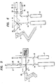
- Figs. 7 and 8 are explanatory diagrams outlining the arrangement of one example of a mechanism for identifying which of the two waveguides is being employed.
- In this example, two guide light sources are employed: a mirror waveguide guide
light source 2 and a fiber waveguide guide light source 2'. - A guide light beam from the guide
light source 2 is combined with the operating light beam by means ofmirrors - The mirror waveguide guide light beam is used as a guide light beam when the mirror waveguide is used. When the fiber waveguide is used, this guide light beam together with the operating light beam are applied to the fiber and serve as a target in adjusting the optical fiber.
- A
beam splitter 76 is provided ahead of the fiber waveguide guide light source 2', and adetector 77 for detecting the guide light beam is provided beside thebeam splitter 76. - An operating
light beam fiber 25 for transmitting infrared rays and a guidelight beam fiber 26 for transmitting visible rays form afiber waveguide 3. - An operating light
beam coupling lens 23 and a guide lightbeam coupling lens 24 are provided immediately before thefibers - The fiber waveguide guide light beam exits the guide
light beam fiber 26 and is then put together with the operating light beam by means ofmirrors - When the
fiber waveguide 3 is placed in front of the light sources and is used, almost all the laser beam from the fiber waveguide guide light source 2' enters the guidelight beam fiber 26, propagates therein and comes out of thefiber 26. No guide light beam is applied to thedetector 77. Thedetector 77 is made up of a suitable light receiving element such as a photo-diode or a photo-transistor. When the fiber waveguide is used, therefore, no guide light beam is applied to thedetector 77, and therefore the output of the latter is substantially zero. - Fig. 8 shows the arrangement when the mirror waveguide is employed.
- The mirror waveguide light beam is reflected by the
mirrors - In this case, no optical fiber is provided on the optical axis of the fiber waveguide guide light source 2', the instead a reflecting
plate 86 is provided. The guide light beam goes through thebeam splitter 76 to the reflectingplate 86, where it is reflected. The guide light beam thus reflected is further reflected by the beam splitter, as a result of which it enters thedetector 77. Therefore, thedetector 77 provides an output voltage. - When the fiber waveguide is used, the output of the detector is substantially zero (0). When the mirror waveguide is used, the
detector 77 provides a significant output other than zero. - Thus, the selected waveguide can be positively detected.
- When the fiber waveguide is used, light enters the detector 17, being reflected from the lens or the fiber end face; however, the amount of source light entering the detector is very small, not more than a few percent. When the mirror waveguide is used, the reflecting
plate 86 may be a mirror or a metal plate. in this case, the amount of reflected light can be readily increased to 90% or more. - The amount of light respecting applied to the detector is thus made to vary greatly. Therefore, the two conditions can be clearly distinguished from one another.
- The above-described arrangement may be modified such that the laser device is arranged so that when the mirror waveguide is used, no reflecting
plate 86, etc. is provided in the optical path of the fiber waveguide guide light beam, and on the other hand, when the fiber waveguide is used, light is reflected by the lens and the fiber end face, and the detector accordingly provides a small output. This method is effective when a relatively large amount of light is reflected from the fiber end face. - The laser device is designed so that, when the two different waveguides are used, different amounts of reflected guide light beam are detected, respectively, as described above. Thus, the selected waveguide can be positively identified.
- In the above-described example, a DC signal is subjected to comparison. Therefore, when external light enters the
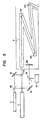
detector 77, the S/N ratio may be decreased. The effect of external light may however be eliminated by employing a method in which a chopper is provided in the optical path of the guide light beam in a manner such that it turns at a predetermined speed so that the guide light beam is subjected to amplitude-modulation at a certain frequency. - In the above-described example, two guide light sources are employed; however, the laser device may be modified so as to employ only one guide light source, as shown in Fig. 9.
- In Fig. 9, a
beam splitter 90 is provided ahead of the guidelight source 2, so as to split the guide light beam into two parts. The first part, or the light beam passed through thebeam splitter 90, serves as a guide light beam in the mirror waveguide. The second part, or the light beam reflected by thebeam splitter 90, is further reflected by amirror 91, so as to be used as a fiber waveguide guide light beam. - The remainder of the arrangement is similar to that of the first example shown in Figs. 7 and 8.
- As is apparent from the above description, a laser device in which a fiber waveguide and a mirror waveguide are selectively used to transmit the operating light beam and the guide light beam; and an automatic identifying mechanism identifies the selected waveguide, to provide a device of improved utility and effectiveness.
- The laser device according to the invention affords the following beneficial effects:
- (1) The laser device of the invention has two different waveguides which can be used selectively. Of the two waveguides, the best one can be selected according to the circumstances and the position and dimensions of the object to which the laser beam should be applied. Thus, the laser device can be used for a plurality of purposes.
- (2) As the power Pw of the operating light beam at the exit of the waveguide can be specified, the desired power can be readily obtained. Thus, operations can be carried out safely, positively and quickly.
- (3) When one of the two waveguides is selected, the laser output power Po is automatically controlled with the operating power Pw set to a desired value. Thus, the laser device according to the invention can be applied to a laser medical treatment device, a laser machining device, or the like.
- The transmission factor nm of the mirror waveguide and the transmission factor nf of the fiber waveguide change; however, the amounts of change are very small, not more than a few percent with age. Thus, the laser beam can be applied to an object with a specified operating power within a range of error of a few percent.
- (4) The completion of a change-over operation can be detected by the provision of a detecting section adapted to detect the states of a selecting mechanism, and therefore the laser device may be operated safely and positively.
- (5) The change-over operation may be detected optically. Therefore, it is unnecessary to provide an electrical circuit near the waveguides, and no trouble due to unsatisfactory insulation is caused.
Claims (10)
Applications Claiming Priority (6)
| Application Number | Priority Date | Filing Date | Title |
|---|---|---|---|
| JP71093/82 | 1982-04-27 | ||
| JP57071093A JPS58188173A (en) | 1982-04-27 | 1982-04-27 | Laser device |
| JP71095/82 | 1982-04-27 | ||
| JP57071095A JPS58188175A (en) | 1982-04-27 | 1982-04-27 | Laser device |
| JP57071094A JPS58188174A (en) | 1982-04-27 | 1982-04-27 | Laser device |
| JP71094/82 | 1982-04-27 |
Publications (3)
| Publication Number | Publication Date |
|---|---|
| EP0093005A2 EP0093005A2 (en) | 1983-11-02 |
| EP0093005A3 EP0093005A3 (en) | 1986-11-20 |
| EP0093005B1 true EP0093005B1 (en) | 1989-03-08 |
Family
ID=27300540
Family Applications (1)
| Application Number | Title | Priority Date | Filing Date |
|---|---|---|---|
| EP19830302327 Expired EP0093005B1 (en) | 1982-04-27 | 1983-04-25 | Laser device |
Country Status (2)
| Country | Link |
|---|---|
| EP (1) | EP0093005B1 (en) |
| DE (1) | DE3379322D1 (en) |
Cited By (1)
| Publication number | Priority date | Publication date | Assignee | Title |
|---|---|---|---|---|
| GB2513123A (en) * | 2013-04-15 | 2014-10-22 | Lumenis Ltd | Adaptor |
Families Citing this family (5)
| Publication number | Priority date | Publication date | Assignee | Title |
|---|---|---|---|---|
| US4739162A (en) * | 1987-02-04 | 1988-04-19 | General Electric Company | Laser beam injecting system |
| WO1989000779A1 (en) * | 1987-07-17 | 1989-01-26 | Kabushiki Kaisha Komatsu Seisakusho | Apparatus for controlling laser wavelength |
| US5364390A (en) * | 1988-05-19 | 1994-11-15 | Refractive Laser Research And Development, Inc. | Handpiece and related apparatus for laser surgery and dentistry |
| CN104688337B (en) * | 2015-02-03 | 2018-01-09 | 中国科学院苏州生物医学工程技术研究所 | A kind of laser therapeutic system of ablation of tissue |
| CN109499007A (en) * | 2018-12-19 | 2019-03-22 | 武汉奇致激光技术股份有限公司 | A kind of dot matrix Super pulse RF excited CO2 laser control system and control method |
Family Cites Families (4)
| Publication number | Priority date | Publication date | Assignee | Title |
|---|---|---|---|---|
| DE2809007A1 (en) * | 1978-03-02 | 1979-09-13 | Messerschmitt Boelkow Blohm | Live tissue cutting and coagulating instrument - has two different wavelength laser beams and pilot light(s) passed together through manipulator to emerge coaxially from it |
| US4316467A (en) * | 1980-06-23 | 1982-02-23 | Lorenzo P. Maun | Control for laser hemangioma treatment system |
| DE3169553D1 (en) * | 1980-09-22 | 1985-05-02 | Olympus Optical Co | A laser device for an endoscope |
| JPS58182886A (en) * | 1982-04-21 | 1983-10-25 | Nippon Sekigaisen Kogyo Kk | Laser irradiation device |
-
1983
- 1983-04-25 EP EP19830302327 patent/EP0093005B1/en not_active Expired
- 1983-04-25 DE DE8383302327T patent/DE3379322D1/en not_active Expired
Cited By (2)
| Publication number | Priority date | Publication date | Assignee | Title |
|---|---|---|---|---|
| GB2513123A (en) * | 2013-04-15 | 2014-10-22 | Lumenis Ltd | Adaptor |
| GB2513123B (en) * | 2013-04-15 | 2015-12-02 | Lumenis Ltd | Adaptor |
Also Published As
| Publication number | Publication date |
|---|---|
| EP0093005A3 (en) | 1986-11-20 |
| DE3379322D1 (en) | 1989-04-13 |
| EP0093005A2 (en) | 1983-11-02 |
Similar Documents
| Publication | Publication Date | Title |
|---|---|---|
| US5012087A (en) | Fiber optic safety system | |
| US4543477A (en) | Safety device for detecting trouble in optical transmission fibers | |
| US4702553A (en) | Fiber-optical sensor for detecting electric arc-discharges | |
| US4812641A (en) | High power optical fiber failure detection system | |
| US4476512A (en) | Monitor device for laser systems transmitting laser light through optical fibers | |
| EP0557719B1 (en) | Apparatus for and method of controlling the output of a laser source | |
| US5463710A (en) | Laser - optical fiber tuning and control system | |
| US4716288A (en) | Security device for detecting defects in transmitting fiber | |
| EP0093005B1 (en) | Laser device | |
| US5323269A (en) | System for transmitting and monitoring laser light and method for optical monitoring of a transmission path | |
| JPS57124586A (en) | Co2 laser working device | |
| JPS6351698B2 (en) | ||
| US4777341A (en) | Back reflection monitor and method | |
| CN110459945B (en) | Laser oscillator | |
| US4730885A (en) | Laser fiber connector | |
| JP4151530B2 (en) | Disaster prevention system for underground space | |
| US6910658B1 (en) | Underwater detection system | |
| JPH0812300B2 (en) | Light irradiation device | |
| JPS5979137A (en) | Detection for disconnection of optical fiber | |
| EP0113104B1 (en) | Device for detecting fractures in power transmission fibers | |
| JPH05277775A (en) | Laser beam machine | |
| US4742217A (en) | Projection alignment and focusing aid | |
| JP4151529B2 (en) | Device for measuring specific gas concentration in tunnel and exhaust method in tunnel | |
| US4544839A (en) | Laser beam monitoring system | |
| JPS58188173A (en) | Laser device |
Legal Events
| Date | Code | Title | Description |
|---|---|---|---|
| PUAI | Public reference made under article 153(3) epc to a published international application that has entered the european phase |
Free format text: ORIGINAL CODE: 0009012 |
|
| AK | Designated contracting states |
Designated state(s): DE FR GB SE |
|
| 17P | Request for examination filed |
Effective date: 19840430 |
|
| PUAL | Search report despatched |
Free format text: ORIGINAL CODE: 0009013 |
|
| AK | Designated contracting states |
Kind code of ref document: A3 Designated state(s): DE FR GB SE |
|
| 17Q | First examination report despatched |
Effective date: 19880502 |
|
| GRAA | (expected) grant |
Free format text: ORIGINAL CODE: 0009210 |
|
| AK | Designated contracting states |
Kind code of ref document: B1 Designated state(s): DE FR GB SE |
|
| REF | Corresponds to: |
Ref document number: 3379322 Country of ref document: DE Date of ref document: 19890413 |
|
| ET | Fr: translation filed | ||
| PLBE | No opposition filed within time limit |
Free format text: ORIGINAL CODE: 0009261 |
|
| STAA | Information on the status of an ep patent application or granted ep patent |
Free format text: STATUS: NO OPPOSITION FILED WITHIN TIME LIMIT |
|
| 26N | No opposition filed | ||
| PGFP | Annual fee paid to national office [announced via postgrant information from national office to epo] |
Ref country code: FR Payment date: 19920408 Year of fee payment: 10 |
|
| PGFP | Annual fee paid to national office [announced via postgrant information from national office to epo] |
Ref country code: GB Payment date: 19920415 Year of fee payment: 10 |
|
| PGFP | Annual fee paid to national office [announced via postgrant information from national office to epo] |
Ref country code: SE Payment date: 19920416 Year of fee payment: 10 |
|
| PGFP | Annual fee paid to national office [announced via postgrant information from national office to epo] |
Ref country code: DE Payment date: 19920521 Year of fee payment: 10 |
|
| PG25 | Lapsed in a contracting state [announced via postgrant information from national office to epo] |
Ref country code: GB Effective date: 19930425 |
|
| PG25 | Lapsed in a contracting state [announced via postgrant information from national office to epo] |
Ref country code: SE Effective date: 19930426 |
|
| GBPC | Gb: european patent ceased through non-payment of renewal fee |
Effective date: 19930425 |
|
| PG25 | Lapsed in a contracting state [announced via postgrant information from national office to epo] |
Ref country code: FR Effective date: 19931229 |
|
| PG25 | Lapsed in a contracting state [announced via postgrant information from national office to epo] |
Ref country code: DE Effective date: 19940101 |
|
| REG | Reference to a national code |
Ref country code: FR Ref legal event code: ST |
|
| EUG | Se: european patent has lapsed |
Ref document number: 83302327.8 Effective date: 19931110 |