EP0092032B1 - Dispositif pour transférer la chaleur d'un conduit de distribution à un consommateur - Google Patents
Dispositif pour transférer la chaleur d'un conduit de distribution à un consommateur Download PDFInfo
- Publication number
- EP0092032B1 EP0092032B1 EP83101367A EP83101367A EP0092032B1 EP 0092032 B1 EP0092032 B1 EP 0092032B1 EP 83101367 A EP83101367 A EP 83101367A EP 83101367 A EP83101367 A EP 83101367A EP 0092032 B1 EP0092032 B1 EP 0092032B1
- Authority
- EP
- European Patent Office
- Prior art keywords
- lines
- line
- longitudinal
- constructed
- opening
- Prior art date
- Legal status (The legal status is an assumption and is not a legal conclusion. Google has not performed a legal analysis and makes no representation as to the accuracy of the status listed.)
- Expired
Links
- 239000011159 matrix material Substances 0.000 claims abstract description 21
- 239000012530 fluid Substances 0.000 claims abstract description 8
- 238000005192 partition Methods 0.000 claims description 3
- 238000010438 heat treatment Methods 0.000 description 17
- 239000007788 liquid Substances 0.000 description 7
- 238000005266 casting Methods 0.000 description 4
- 238000004519 manufacturing process Methods 0.000 description 4
- 230000004888 barrier function Effects 0.000 description 3
- 238000000034 method Methods 0.000 description 3
- 238000005259 measurement Methods 0.000 description 2
- 210000000056 organ Anatomy 0.000 description 2
- 238000007789 sealing Methods 0.000 description 2
- XLYOFNOQVPJJNP-UHFFFAOYSA-N water Substances O XLYOFNOQVPJJNP-UHFFFAOYSA-N 0.000 description 2
- 229910001060 Gray iron Inorganic materials 0.000 description 1
- WYTGDNHDOZPMIW-RCBQFDQVSA-N alstonine Natural products C1=CC2=C3C=CC=CC3=NC2=C2N1C[C@H]1[C@H](C)OC=C(C(=O)OC)[C@H]1C2 WYTGDNHDOZPMIW-RCBQFDQVSA-N 0.000 description 1
- 230000000903 blocking effect Effects 0.000 description 1
- 238000009529 body temperature measurement Methods 0.000 description 1
- 239000003638 chemical reducing agent Substances 0.000 description 1
- 238000009413 insulation Methods 0.000 description 1
- 230000001105 regulatory effect Effects 0.000 description 1
- 238000000926 separation method Methods 0.000 description 1
Images


Classifications
-
- F—MECHANICAL ENGINEERING; LIGHTING; HEATING; WEAPONS; BLASTING
- F24—HEATING; RANGES; VENTILATING
- F24D—DOMESTIC- OR SPACE-HEATING SYSTEMS, e.g. CENTRAL HEATING SYSTEMS; DOMESTIC HOT-WATER SUPPLY SYSTEMS; ELEMENTS OR COMPONENTS THEREFOR
- F24D10/00—District heating systems
- F24D10/006—Direct domestic delivery stations
-
- F—MECHANICAL ENGINEERING; LIGHTING; HEATING; WEAPONS; BLASTING
- F24—HEATING; RANGES; VENTILATING
- F24D—DOMESTIC- OR SPACE-HEATING SYSTEMS, e.g. CENTRAL HEATING SYSTEMS; DOMESTIC HOT-WATER SUPPLY SYSTEMS; ELEMENTS OR COMPONENTS THEREFOR
- F24D3/00—Hot-water central heating systems
- F24D3/10—Feed-line arrangements, e.g. providing for heat-accumulator tanks, expansion tanks ; Hydraulic components of a central heating system
- F24D3/1058—Feed-line arrangements, e.g. providing for heat-accumulator tanks, expansion tanks ; Hydraulic components of a central heating system disposition of pipes and pipe connections
- F24D3/1066—Distributors for heating liquids
-
- Y—GENERAL TAGGING OF NEW TECHNOLOGICAL DEVELOPMENTS; GENERAL TAGGING OF CROSS-SECTIONAL TECHNOLOGIES SPANNING OVER SEVERAL SECTIONS OF THE IPC; TECHNICAL SUBJECTS COVERED BY FORMER USPC CROSS-REFERENCE ART COLLECTIONS [XRACs] AND DIGESTS
- Y02—TECHNOLOGIES OR APPLICATIONS FOR MITIGATION OR ADAPTATION AGAINST CLIMATE CHANGE
- Y02B—CLIMATE CHANGE MITIGATION TECHNOLOGIES RELATED TO BUILDINGS, e.g. HOUSING, HOUSE APPLIANCES OR RELATED END-USER APPLICATIONS
- Y02B30/00—Energy efficient heating, ventilation or air conditioning [HVAC]
- Y02B30/17—District heating
-
- Y—GENERAL TAGGING OF NEW TECHNOLOGICAL DEVELOPMENTS; GENERAL TAGGING OF CROSS-SECTIONAL TECHNOLOGIES SPANNING OVER SEVERAL SECTIONS OF THE IPC; TECHNICAL SUBJECTS COVERED BY FORMER USPC CROSS-REFERENCE ART COLLECTIONS [XRACs] AND DIGESTS
- Y02—TECHNOLOGIES OR APPLICATIONS FOR MITIGATION OR ADAPTATION AGAINST CLIMATE CHANGE
- Y02E—REDUCTION OF GREENHOUSE GAS [GHG] EMISSIONS, RELATED TO ENERGY GENERATION, TRANSMISSION OR DISTRIBUTION
- Y02E20/00—Combustion technologies with mitigation potential
- Y02E20/14—Combined heat and power generation [CHP]
-
- Y—GENERAL TAGGING OF NEW TECHNOLOGICAL DEVELOPMENTS; GENERAL TAGGING OF CROSS-SECTIONAL TECHNOLOGIES SPANNING OVER SEVERAL SECTIONS OF THE IPC; TECHNICAL SUBJECTS COVERED BY FORMER USPC CROSS-REFERENCE ART COLLECTIONS [XRACs] AND DIGESTS
- Y02—TECHNOLOGIES OR APPLICATIONS FOR MITIGATION OR ADAPTATION AGAINST CLIMATE CHANGE
- Y02P—CLIMATE CHANGE MITIGATION TECHNOLOGIES IN THE PRODUCTION OR PROCESSING OF GOODS
- Y02P80/00—Climate change mitigation technologies for sector-wide applications
- Y02P80/10—Efficient use of energy, e.g. using compressed air or pressurized fluid as energy carrier
- Y02P80/14—District level solutions, i.e. local energy networks
Definitions
- the invention relates to a device for transferring heat stored in a fluid from a supply line to a customer, with supply flow, supply return, customer supply run, return and optionally bypass and / or safety line.
- the invention has for its object to provide, while avoiding the aforementioned disadvantages, a compact, light-weight device of the generic type which is simple to manufacture and which can be variably adapted in the factory to suit a wide variety of requirements with regard to measurement and control processes.
- the stated object is achieved in that at least partially intersecting longitudinal and transverse casting block lines are provided; that the lines are connected to one another at least at some of their crossing points without intermediate branch pipe parts; that barrier walls are provided in the lines, which have a longitudinal section extending parallel to the direction of the line; and that the casting block is designed as a variable matrix, in which closable passages are formed in longitudinal sections of the barrier walls and in a neighboring outer wall with a passageway a closable opening which is at least as large in diameter as the passageway.
- the invention thus creates a device in the form of a hand plate system which, as a central transfer element, enables hot water from a district heating plant to be processed for the customer system by measuring and regulating pressures, temperatures and volume flows.
- the device according to the invention is created from a few individual parts and advantageously cast in a block, with all the necessary connecting lines and bypass lines, safety lines etc. then already being provided in the matrix-shaped arrangement and only having to be switched in a suitable manner.
- the device according to the invention thus represents a variable interface for connecting the district heating system and the consumer. It can also be designed in a much smaller size than was previously the case. Characterized in that separate connecting elements are omitted and these are also integrated in the matrix-shaped casting block part, considerable weight savings are possible with the same pressure resistance.
- a further significant advantage is that the device according to the invention can be adapted to a wide variety of different requirements by shutting off individual branches, etc., in particular by performing switching operations.
- a preferred embodiment of the device according to the invention is characterized in particular in that the main axes of the longitudinal and transverse lines lie in parallel planes with a limited distance. As a result, an optimum is achieved in terms of production.
- the device is to be made flat so that it can be accommodated in a convenient manner in a housing which can then also be insulated against heat loss.
- a closable passage is formed in the partition between a longitudinal and a transverse line.
- Cross and longitudinal lines can either cross without them communicate with each other by being separated by a completely closed bulkhead.
- the transverse and longitudinal lines can also be connected by providing an opening in the transverse or longitudinal wall, which can then, if necessary, be subsequently closed from the outside by means of a screw cap.
- the connection passage can also serve for a valve seat, whereby a control of the liquid flow from a cross line to a longitudinal line is possible at the crossing point.
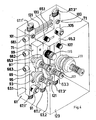
- the device according to the invention shown in FIG. 1 for transferring heat from a supply line to a consumer consists of a grid or a matrix 11 of lines.
- three longitudinal lines 13.1, 13.2 and 13.3 and as many connecting or transverse lines 15.1, 15.2 and 15.3 are provided, which, as can be seen, do not all lead completely over the lines running perpendicular to a line in question, but are in some cases shorter.
- each line 13, 15 need not be provided with connection options 17.
- the lines 13, 15 consist of square die-cast, the entire matrix 11 being made in one piece.
- Each line 13, 15 is provided with openings 21 at least on the side surface 19 visible in FIG.
- the openings generally have a screw thread, so that further components and elements such as switching components, controllers, valves etc. can be installed at the openings or, if such an element is not necessary, a sealing plug can be screwed in.
- the internal structure of the matrix 11 is designed in a corresponding manner, as can be seen in FIG.
- an interrupted longitudinal wall 23 is provided in its interior, through which the liquid path runs in a somewhat serpentine manner.
- the interruptions or openings 25 of the longitudinal wall 23 are aligned with an opening 21 in each case.
- the diameters of the openings 25 are at most as large as the diameter of the openings 21, but preferably smaller, so that through the opening 21 a specific one for the associated opening 25 Element can be introduced.
- the openings 25 preferably have a screw thread on the one hand, so that, for example, closures can also be used in them and / or on the other hand a conical valve seat. Preferred configuration.
- the breakthroughs 25 are explained further below.
- connection opening 25 'between the longitudinal line 13.3 and the transverse line 15.1 in FIG. 2 cannot be closed (see below for the opening 25: 4), so that in the event that no connection is established between the longitudinal line 13.3 and the transverse line 15.1 should proceed as follows:
- the openings 25.1 and 25.2 are closed from the openings 21.1 and 21.2 by means of screw plugs 27.1 and 27.2. This prevents the lines 13.3 and 15.1 from being connected, since the branch 29 of the line 13.3 is blocked off by the plugs 27.1 and 27.2.
- line 13.3 is interrupted per se. The interruption is therefore bridged from the opening 21.1 to an opening 21.2 by means of a bypass 31, so that the fluid can take the path shown in broken lines in FIG.
- the opening 21.3 is closed with a screw plug 33.1, while the associated opening 25.3 is not closed, so that here the fluid can pass through unhindered.
- the opening 25.4 is therefore also closed by means of a screw plug 27.4 which has been introduced into the line 13.3 through the opening 21.4.
- a sensor 35 for measuring a size of the fluid in the transverse line 15.2 is seated in the opening 21.4, for example a temperature meter.
- An actuator 37 is arranged in the opening 21.5 and the opening 25.5 21.5 is fixed and can regulate the flow of line 13.3 by means of its valve cone 39, which engages in the opening 25.5.
- the opening 25.6 is again completely open and the associated opening 21.6 is closed with a plug 33.6.
- the connection opening 25 "between the longitudinal line 13.3 and the transverse line 15.3 is open so that fluid can pass between the two lines. If the opening 25" had been assigned a corresponding opening, a control element or a shut-off device in the opening 25.7 to be ordered.
- the opening 21.7 adjoining the opening 25 is closed by a screw plug 33.7, while the associated opening 25.7 is open.
- liquid can flow between the connection 17.3 'and the connection 17.3" along the line shown in dashed lines in the line 13.3.
- Various switching components such as shut-off devices, control elements, measuring elements, such as temperature sensors, can be arranged in the openings 21 and the associated openings 25.
- the matrix 11 can be switched and set up in a variety of ways adapted to a wide variety of requirements by means of such components and elements in the openings and openings.
- FIG. 3 Another exemplary embodiment is shown in FIG. 3, in which the longitudinal lines, of which a longitudinal line 43.3 is represented and the transverse lines, of which a transverse line 45.1 and a transverse line 45.2 are represented, are not formed in one piece. Rather, the matrix 42 in FIG. 3 arises from square tubes corresponding to 45.1, 45.2 and 43.3. are welded to one another in a grid-like manner, with openings 55 ′ and 55 ′′ between transverse and longitudinal lines being provided in the connection areas 47, so that, if desired, liquid can flow between the transverse and longitudinal lines.
- the lines point in accordance with the configuration of the figure 2, also along its longitudinal direction extending bulkhead or interruption walls 53 or 53 'with openings 55.
- the outer wall 49 of the lines is provided with openings 51 which are each aligned with an associated opening 55 in the partition wall 53.
- the matrix 41 of FIG Figure 3 can be provided in the same way as the matrix of Figures 1 and 2 with the components and elements mentioned in the openings 51 and the openings 55.
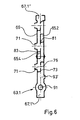
- the device according to the invention of FIG. 4 consists of a grid or a matrix 61 made of square tubes.
- the matrix 61 is made in one piece from pressure or gray cast iron.
- the matrix 61 has three longitudinal lines 63.1, 63.2 and 63.3 as well as four cross lines 65.1, 65.2, 65.3 and 65.4 (FIG. 5), the latter two being largely covered in FIG. 4 and 65.2 being visible only in a short piece. All lines 63, 65 have connections for connecting conventional pipes.
- the longitudinal line 63.1 has the connections 67.1 'and 67.1 ".
- the longitudinal lines 63.2 and 63.3 have corresponding connections 67.2' or 67.3 'and 67.3".
- the longitudinal line 63.2 thus has only one connection 67.2 '.
- the cross lines 65.3 and 65.4 each have a connection 68.2 and 68.3.
- the viewer facing, extending in the matrix plane surface 69 ( Figure 6) of the device according to the invention is provided in the manner already described with openings 71, all of which are closed with shut-off devices, regulators, actuators or measuring elements in the illustrated embodiment.
- the openings 71 are again aligned with openings 75 in longitudinal sections with a longitudinal electrode barrier wall 73, which are visible in particular in FIGS. 6 to 8.
- connection 67.1 ' serves as a flow inlet for the flow of the supply line, such as a district heating supply or the like.
- the connection 67.1' is the outlet of the device according to the invention for the flow of the consumer or consumer, such as a heating system of a house.
- connection 67.3 ' the return of the consumer comes back to the device according to the invention and is then delivered via connection 67.3 'to the return of the supply system.
- Flow 67.1 "and return 67.3" of the customer are connected to one another via the bypass line 65.1, so that liquid from the return can be mixed with the flow as required.
- the device according to the invention is used as a so-called central office and is then already part of the consumer or domestic circuit.
- the device according to the invention is made available by the district heating supplier as a so-called district heating transfer station, in which case no return admixture should be given in such stations , as this is not part of the obligations of the district heating supplier.
- the connection on the house side is the responsibility of the heat consumer.
- the "house circuit” will only begin after connections 67.1 "and 67.3" and have its own bypass. If such a separation is desired, two compact devices according to the invention of different or the same basic shape can also be connected in series, whereby the first serves as a district heating transfer station and the second as a house control center.
- Liquid is branched off from the supply flow line 63.1 via the cross lines 65.3, on the one hand to the longitudinal line 63.2 serving as a safety overflow bypass, from which on the other hand a boiler flow to the connection 68.3 is taken off via the cross line 65.4.
- the boiler return takes place via the connection 68.2 and the connected cross line 65.2 to the supply return in the longitudinal line 63.3.
- Boiler flow and boiler return, i.e. the cross lines 65.4 and 65.2 cross the longitudinal line 63.1 without the possibility of replacement. Continuous, sealing bulkheads 81, 83 are therefore provided here (FIG. 6).
- connection 68.1 leading out of the longitudinal line 63.1 above the boiler return connection 68.2 serves as a safety outlet and as such is provided with a safety valve (not shown).
- the safety overflow line 63.2 can be returned to the supply return, which could also be done by a further cross line, in contrast to the specific embodiment shown.
- the heating fluid supplied by the supply line 67.1 'thus flows via line 63.1 to the heating flow at outlet 67.1 "on the one hand, and via cross line 65.3 to the longitudinal line 63.2 serving as a safety overflow bypass, but also via cross line 65.4 to the boiler flow.
- the consumer or heating return takes place via the connection 67.3 "to the longitudinal line 63.3 and thus via the connection 67.3 'to the supply return.
- An admixture of the consumer return to the consumer flow is possible via the bypass cross lines 65.1.
- the boiler returns via the transverse line 65.2 crossing the longitudinal line 63.1 to the return longitudinal line 63.3 without a connection.
- a dirt trap 91 is first arranged, which prevents dirt from getting into the customer system from the supply system.
- a supply flow temperature sensor 93 (FIG. 4), for which, in the embodiment according to FIGS. 5 and 6, a connection opening 93 'is provided on the surface opposite surface 69.
- the temperature sensor 93 works in conjunction with the flow and heat meter (not shown).
- a safety fitting 95 which blocks the line 63.1 when the subsequent pressure reducer 97 fails.
- the next valve is a motor valve 99 that regulates the flow.
- a temperature sensor 101 for measuring the temperature of the consumer flow is provided above the motor valve 99.
- a temperature sensor 103 with a connection opening 103 '(FIG. 7) for the consumer return is initially provided in the return line 63.3 from top to bottom.
- Flow and return temperature sensors 101 and 103 determine, if necessary in connection with other parameters, the regulation of the flow temperature of the consumer, namely by admixing the return flow portion via the Qeru ein 65.1 to the consumer flow by means of the motor valve 99 Circulation to the consumer circuit provided a pump (not shown).
- a dirt trap 105 which prevents dirt from the consumer circuit from entering the supply system.
- Flow adjusters 107 and 109 combined with non-return elements are also provided in line 63.3, but also in line 65.1.
- a combined differential pressure and flow controller 111 is installed in the return line to regulate the total flow between the supply flow and return. This is then followed by a shut-off valve 113 (FIG. 7).
- a valve 115 for temperature control in the boiler is arranged in the second (bypass) longitudinal line 63.2 at the interface to the boiler flow, namely to the cross line 65.4, which is set via the temperature measurement in the boiler by means of a temperature sensor (not shown)
- a device according to the invention can be switched and used in a wide variety of ways due to its matrix shape, the individual organs and components mentioned with regard to FIGS. 5 to 8 being listed only by way of example.
- the matrix 61 itself can be reinforced and stabilized by cross struts 121.
- the arrangement is housed in a housing 123, which vorzugswei se is provided with insulation.
- the entire arrangement is fastened to a wall using fastening projections (not shown) which can be formed in one piece with the matrix 61.
Landscapes
- Engineering & Computer Science (AREA)
- Physics & Mathematics (AREA)
- Thermal Sciences (AREA)
- Chemical & Material Sciences (AREA)
- Combustion & Propulsion (AREA)
- Mechanical Engineering (AREA)
- General Engineering & Computer Science (AREA)
- Pipeline Systems (AREA)
- Steam Or Hot-Water Central Heating Systems (AREA)
- Heat-Exchange Devices With Radiators And Conduit Assemblies (AREA)
Claims (13)
Priority Applications (1)
| Application Number | Priority Date | Filing Date | Title |
|---|---|---|---|
| AT83101367T ATE19546T1 (de) | 1982-04-21 | 1983-02-12 | Vorrichtung zum uebergeben von waerme von einer versorgungsleitung zu einem abnehmer. |
Applications Claiming Priority (2)
| Application Number | Priority Date | Filing Date | Title |
|---|---|---|---|
| DE3214775 | 1982-04-21 | ||
| DE3214775A DE3214775C2 (de) | 1982-04-21 | 1982-04-21 | Vorrichtung zum Übergeben von wärmeführenden Fluid von einer Versorgungsleitung eines Fernheizkraftwerks zu einem Abnehmer |
Publications (3)
| Publication Number | Publication Date |
|---|---|
| EP0092032A2 EP0092032A2 (fr) | 1983-10-26 |
| EP0092032A3 EP0092032A3 (en) | 1984-03-28 |
| EP0092032B1 true EP0092032B1 (fr) | 1986-04-30 |
Family
ID=6161510
Family Applications (1)
| Application Number | Title | Priority Date | Filing Date |
|---|---|---|---|
| EP83101367A Expired EP0092032B1 (fr) | 1982-04-21 | 1983-02-12 | Dispositif pour transférer la chaleur d'un conduit de distribution à un consommateur |
Country Status (3)
| Country | Link |
|---|---|
| EP (1) | EP0092032B1 (fr) |
| AT (1) | ATE19546T1 (fr) |
| DE (2) | DE3214775C2 (fr) |
Families Citing this family (12)
| Publication number | Priority date | Publication date | Assignee | Title |
|---|---|---|---|---|
| DE3241536A1 (de) * | 1982-11-10 | 1984-05-10 | Grammer, Meinrad, Ing.(grad.), 7407 Rottenburg | Anschlussvorrichtung fuer heizungsanlagen |
| EP0222040A3 (fr) * | 1985-11-11 | 1988-03-30 | IWK Regler und Kompensatoren GmbH | Installation de la technique du chauffage |
| DE3814052A1 (de) * | 1987-06-12 | 1988-12-22 | Steag Fernwaerme | Fernwaerme-uebergabevorrichtung |
| EP1284394B1 (fr) | 1998-04-20 | 2007-07-11 | Sundsvall Energi AB | Procédé de régulation d'un echangeur de chaleur |
| DE19912821C2 (de) * | 1999-03-22 | 2002-09-26 | Kermi Gmbh | Ventilanordnung |
| GB2388422A (en) * | 2002-05-08 | 2003-11-12 | Heatrae Sadia Heating Ltd | Support platform for mounting control devices of a fluid system |
| GB0525157D0 (en) * | 2005-12-09 | 2006-01-18 | Ec Power As | Fluid distributor |
| SE532136C2 (sv) * | 2006-10-04 | 2009-10-27 | Tour & Andersson Ab | Anordning för ett energidistributionssystem |
| DE102009048585A1 (de) | 2009-10-07 | 2011-04-14 | Stiebel Eltron Gmbh & Co. Kg | Hydraulikmodul für ein Haustechnikgerät und Wärmepumpe mit einem Hydraulikmodul |
| DE102011005365A1 (de) * | 2011-03-10 | 2012-09-13 | Michael Hertneck | Flächenheizeinrichtung und Anschlussbox |
| NL2014236B1 (nl) * | 2015-02-05 | 2016-10-12 | J H Chardet Loodgietersbedrijf | Geïntegreerd tussenstuk voor een vloerverwarmingsinstallatie. |
| CN115523524A (zh) * | 2021-06-24 | 2022-12-27 | 丹佛斯有限公司 | 模块化供暖站 |
Family Cites Families (2)
| Publication number | Priority date | Publication date | Assignee | Title |
|---|---|---|---|---|
| FR1284727A (fr) * | 1961-02-03 | 1962-02-16 | Perfectionnements aux raccords de tuyau d'installation de chauffage central | |
| DE2014093C3 (de) * | 1970-03-18 | 1974-01-17 | Rietschel & Henneberg, 12000 Hamburg | Verteil- und Sammeleinrichtung für eine Heizanlage |
-
1982
- 1982-04-21 DE DE3214775A patent/DE3214775C2/de not_active Expired
-
1983
- 1983-02-12 AT AT83101367T patent/ATE19546T1/de not_active IP Right Cessation
- 1983-02-12 EP EP83101367A patent/EP0092032B1/fr not_active Expired
- 1983-02-12 DE DE8383101367T patent/DE3363240D1/de not_active Expired
Also Published As
| Publication number | Publication date |
|---|---|
| EP0092032A3 (en) | 1984-03-28 |
| DE3214775C2 (de) | 1986-09-25 |
| DE3214775A1 (de) | 1983-11-10 |
| EP0092032A2 (fr) | 1983-10-26 |
| ATE19546T1 (de) | 1986-05-15 |
| DE3363240D1 (en) | 1986-06-05 |
Similar Documents
| Publication | Publication Date | Title |
|---|---|---|
| EP0903543B1 (fr) | Distributeur d'un circuit rempli de fluide d'une installation de chauffage ou de réfrigération | |
| DE3043422C2 (fr) | ||
| EP0092032B1 (fr) | Dispositif pour transférer la chaleur d'un conduit de distribution à un consommateur | |
| DE3439585C2 (fr) | ||
| EP2855786B1 (fr) | Système de raccordement à l'eau doté d'un distributeur et collecteur d'eau combiné | |
| EP0109032B1 (fr) | Installation de chauffage à distance avec un dispositif de raccordement | |
| DE3203964C2 (de) | Abzweigeeinheit für eine Heizungs- oder Kühlanlage | |
| DE19637575B4 (de) | Verteilerstation für ein Heizungssystem | |
| DE3313352C2 (fr) | ||
| DE10244256A1 (de) | Heizanlage und/oder Kühlanlage mit mindestens einer Wärmequelle | |
| DE3419498A1 (de) | Vorrichtung zur verteilung von rohren in heizungsanlagen | |
| DE8909284U1 (de) | Gradsitzstrangventil | |
| EP0612963A2 (fr) | Groupe distributeur pour des installations de chauffage et/ou réfrigération fonctionnant par un agent caloporteur étant capable de circuler | |
| DE3425144A1 (de) | In der kaverne eines druckbehaelters angeordnete kernreaktoranlage | |
| EP0240860B1 (fr) | Chaudière de chauffage | |
| DE3743771C2 (fr) | ||
| DE4005745C2 (fr) | ||
| DE4228512C2 (de) | Verteileranordnung für Heizungsanlagen | |
| DE29519901U1 (de) | Fußbodenheizung mit Einzelraum-Temperaturregelung | |
| DE3502428C2 (fr) | ||
| DE9317935U1 (de) | Verteileraggregat für mit einem strömungsfähigen Wärmeträgermedium arbeitende Heiz- oder Kühlanlagen | |
| AT405097B (de) | Anschlussarmatur für den anschluss eines heizkörpers an ein zweirohr-verteilersystem einer heizungsanlage | |
| DE9306257U1 (de) | Wasserverteiler | |
| DE1925426U (de) | Luft- bzw. gasverteilungsstation. | |
| DE3045860A1 (de) | Vorrichtung fuer den parallelanschluss mehrerer fluessigkeits- oder gasdurchstroemter geraete an eine zulauf- und eine ruecklaufsammelleitung |
Legal Events
| Date | Code | Title | Description |
|---|---|---|---|
| PUAI | Public reference made under article 153(3) epc to a published international application that has entered the european phase |
Free format text: ORIGINAL CODE: 0009012 |
|
| AK | Designated contracting states |
Designated state(s): AT BE CH DE FR GB IT LI NL |
|
| PUAL | Search report despatched |
Free format text: ORIGINAL CODE: 0009013 |
|
| AK | Designated contracting states |
Designated state(s): AT BE CH DE FR GB IT LI NL |
|
| 17P | Request for examination filed |
Effective date: 19840913 |
|
| GRAA | (expected) grant |
Free format text: ORIGINAL CODE: 0009210 |
|
| AK | Designated contracting states |
Kind code of ref document: B1 Designated state(s): AT BE CH DE FR GB IT LI NL |
|
| PG25 | Lapsed in a contracting state [announced via postgrant information from national office to epo] |
Ref country code: BE Effective date: 19860430 |
|
| REF | Corresponds to: |
Ref document number: 19546 Country of ref document: AT Date of ref document: 19860515 Kind code of ref document: T |
|
| ET | Fr: translation filed | ||
| REF | Corresponds to: |
Ref document number: 3363240 Country of ref document: DE Date of ref document: 19860605 |
|
| RBV | Designated contracting states (corrected) |
Designated state(s): AT BE CH FR GB IT LI NL |
|
| ITF | It: translation for a ep patent filed |
Owner name: DR. ING. A. RACHELI & C. |
|
| PLBE | No opposition filed within time limit |
Free format text: ORIGINAL CODE: 0009261 |
|
| STAA | Information on the status of an ep patent application or granted ep patent |
Free format text: STATUS: NO OPPOSITION FILED WITHIN TIME LIMIT |
|
| 26N | No opposition filed | ||
| GBPC | Gb: european patent ceased through non-payment of renewal fee | ||
| PG25 | Lapsed in a contracting state [announced via postgrant information from national office to epo] |
Ref country code: GB Effective date: 19881122 |
|
| PGFP | Annual fee paid to national office [announced via postgrant information from national office to epo] |
Ref country code: FR Payment date: 19890131 Year of fee payment: 7 |
|
| ITTA | It: last paid annual fee | ||
| PGFP | Annual fee paid to national office [announced via postgrant information from national office to epo] |
Ref country code: NL Payment date: 19890228 Year of fee payment: 7 |
|
| PG25 | Lapsed in a contracting state [announced via postgrant information from national office to epo] |
Ref country code: NL Effective date: 19900901 |
|
| NLV4 | Nl: lapsed or anulled due to non-payment of the annual fee | ||
| PG25 | Lapsed in a contracting state [announced via postgrant information from national office to epo] |
Ref country code: FR Effective date: 19901031 |
|
| REG | Reference to a national code |
Ref country code: FR Ref legal event code: ST |
|
| PGFP | Annual fee paid to national office [announced via postgrant information from national office to epo] |
Ref country code: AT Payment date: 19910214 Year of fee payment: 9 |
|
| PGFP | Annual fee paid to national office [announced via postgrant information from national office to epo] |
Ref country code: CH Payment date: 19910422 Year of fee payment: 9 |
|
| PG25 | Lapsed in a contracting state [announced via postgrant information from national office to epo] |
Ref country code: AT Effective date: 19920212 |
|
| PG25 | Lapsed in a contracting state [announced via postgrant information from national office to epo] |
Ref country code: LI Effective date: 19920229 Ref country code: CH Effective date: 19920229 |
|
| REG | Reference to a national code |
Ref country code: CH Ref legal event code: PL |