EP0091156B1 - Appareil pour la réduction de la largeur d'une brame d'acier par laminage - Google Patents
Appareil pour la réduction de la largeur d'une brame d'acier par laminage Download PDFInfo
- Publication number
- EP0091156B1 EP0091156B1 EP83200418A EP83200418A EP0091156B1 EP 0091156 B1 EP0091156 B1 EP 0091156B1 EP 83200418 A EP83200418 A EP 83200418A EP 83200418 A EP83200418 A EP 83200418A EP 0091156 B1 EP0091156 B1 EP 0091156B1
- Authority
- EP
- European Patent Office
- Prior art keywords
- rolling
- edge
- slab
- elements
- rolling elements
- Prior art date
- Legal status (The legal status is an assumption and is not a legal conclusion. Google has not performed a legal analysis and makes no representation as to the accuracy of the status listed.)
- Expired
Links
- 238000005096 rolling process Methods 0.000 title claims abstract description 140
- 229910000831 Steel Inorganic materials 0.000 title claims description 8
- 239000010959 steel Substances 0.000 title claims description 8
- 230000009467 reduction Effects 0.000 description 8
- 238000007688 edging Methods 0.000 description 6
- 239000000463 material Substances 0.000 description 6
- 230000001788 irregular Effects 0.000 description 5
- 230000008901 benefit Effects 0.000 description 3
- 230000015572 biosynthetic process Effects 0.000 description 3
- 230000007246 mechanism Effects 0.000 description 3
- 238000009749 continuous casting Methods 0.000 description 2
- 230000001419 dependent effect Effects 0.000 description 2
- 230000000694 effects Effects 0.000 description 2
- 230000008719 thickening Effects 0.000 description 2
- 230000009471 action Effects 0.000 description 1
- 238000005098 hot rolling Methods 0.000 description 1
- 238000004519 manufacturing process Methods 0.000 description 1
- 238000000034 method Methods 0.000 description 1
Images


Classifications
-
- B—PERFORMING OPERATIONS; TRANSPORTING
- B21—MECHANICAL METAL-WORKING WITHOUT ESSENTIALLY REMOVING MATERIAL; PUNCHING METAL
- B21B—ROLLING OF METAL
- B21B1/00—Metal-rolling methods or mills for making semi-finished products of solid or profiled cross-section; Sequence of operations in milling trains; Layout of rolling-mill plant, e.g. grouping of stands; Succession of passes or of sectional pass alternations
- B21B1/02—Metal-rolling methods or mills for making semi-finished products of solid or profiled cross-section; Sequence of operations in milling trains; Layout of rolling-mill plant, e.g. grouping of stands; Succession of passes or of sectional pass alternations for rolling heavy work, e.g. ingots, slabs, blooms, or billets, in which the cross-sectional form is unimportant ; Rolling combined with forging or pressing
- B21B1/026—Rolling
-
- B—PERFORMING OPERATIONS; TRANSPORTING
- B21—MECHANICAL METAL-WORKING WITHOUT ESSENTIALLY REMOVING MATERIAL; PUNCHING METAL
- B21B—ROLLING OF METAL
- B21B13/00—Metal-rolling stands, i.e. an assembly composed of a stand frame, rolls, and accessories
- B21B13/06—Metal-rolling stands, i.e. an assembly composed of a stand frame, rolls, and accessories with axes of rolls arranged vertically, e.g. edgers
-
- B—PERFORMING OPERATIONS; TRANSPORTING
- B21—MECHANICAL METAL-WORKING WITHOUT ESSENTIALLY REMOVING MATERIAL; PUNCHING METAL
- B21B—ROLLING OF METAL
- B21B13/00—Metal-rolling stands, i.e. an assembly composed of a stand frame, rolls, and accessories
- B21B13/18—Metal-rolling stands, i.e. an assembly composed of a stand frame, rolls, and accessories for step-by-step or planetary rolling; pendulum mills
Definitions
- the invention relates to an apparatus for reducing the width of a steel slab by rolling, comprising edge-rolling elements, the rolling surfaces of which are moved in a rolling manner on the edges of the steel slab.
- width rolling Reducing the width of a steel slab by rolling (hereinafter called width rolling) is an important development in the field of the hot strip rolling of steel.
- width rolling is carried out directly after the continuous casting of the slab. In most cases however, it is best to carry out width rolling in the hot strip rolling mill.
- the known width rolling is carried out with edge rolls.
- the diameter of the edge rolls is up to approximately 800 mm. Only a small reduction in width, by a maximum of 40-60 mm can be obtained with these edge rolls. With a greater width reduction one experiences problems when feeding the slab into the edge rolls. For this reason, larger diameter edge rolls have been adopted, going up to 1200 mm diameter as shown in US 3,757 556. With a diameter of 1200 mm, the maximum width reduction per pass is 150 mm; at this width there is substantial dog-bone formation as will now be discussed.
- width rolling is the irregular deformation of the piece being rolled. Firstly the material is not spread evenly over the width during width rolling; but ends up thicker at the edges. In a cross-section at right angles to the direction of rolling, the piece being rolled exhibits a so-called dog-bone shape after rolling. This effect can be minimized by using the caliber rolls known from US 3,757,556, but even then the maximum width reduction is limited by the formation of a dog-bone to the maximum of 100 mm per pass, after which the resulting dog-bone can largely be rolled flat during the following thickness rolling pass. Also during thickness rolling, part of the width reduction obtained by width rolling is lost as a result of expansion of the piece being rolled. Secondly, the material is not distributed evenly in the longitudinal direction during width rolling.
- the elongation of the slab is not uniform in the middle and at the sides, as a result of which the original square ends of the head and tail of the slab exhibit a so-called fish-tail shape after width rolling.
- This effect is further amplified by thickness rolling, after width rolling, in which, during rolling flat of the dog-bone shape, irregular elongation of the slab also occurs.
- This deformation results in a loss of material as the deformed ends have to be cut off before final rolling in the hot strip rolling mill. As a result of this the slab output is smaller for width rolling.
- edge-rolling elements are circular-section cylindrical rolls, there are technical and economic drawbacks, especially if the rolls are very large, e.g. 5 m radius.
- One drawback is simply the space which they take up.
- the rolling elements it is not necessary for the rolling elements to be circular-section rolls.
- the contact surface between the slab and the rolling element is only a portion of the full circumference of the roll, and a rolling element need only provide an appropriately curved surface in the zone of rolling contact.
- the present invention provides apparatus for reducing the width of the steel slab by rolling having a pair of opposed edge rolling elements which each provide, at the zone of rolling contact with the slab, a curved surface which is a sector of angular length less than 180°. In this way, we can avoid the use of large rolls, while retaining the benefit of reduced deformation and greater output.
- the roll elements no longer need to be able to rotate through 360°. After a pass corresponding to the arc length of the sector the roll elements can be returned to roll the next slab or the next section of the slab.
- the angular length of the curved surface is no more than 90°.
- edge-rolling elements with a greater diameter it is preferable for there not to be a physical centre of rotation, as in full-circle cylindrical edging rolls, but for the edge-rolling elements to be designed such that measured in a direction at right angles to the rolling surface they are of a thickness which is smaller than the radius of curvature of the rolling surface.
- the rolling movement of the edge-rolling elements and the sides of the slab is here produced by an appropriate movement mechanism of the edge-rolling elements and/or slab.
- the geometric centre of the rolling surface of the edge-rolling elements can be moved in a direction parallel to and opposite to the direction of rolling.
- the apparatus also includes a number of back-up rolls, which form a path for the edge-rolling elements and which, during rolling, cooperate to support the side of the edge-rolling elements facing away from the slab.
- the edge-rolling elements are preferably designed with grooves, like caliber rolls, where the bottom of the groove forms the roll surface.
- the edge-rolling elements may also be flexible in the direction of rolling and during rolling have a curve dependent on the track formed by the back-up rolls.
- the edge-rolling elements are preferably made in the form of caterpillar or apron conveyors, which are closed to themselves.
- the irregular deformation of the length and thickness of the slab during width rolling is smaller the greater the radius of curvature of the edge-rolling elements.
- a radius of curvature which is only slightly greater than the conventional maximum radius of curvature of 0.6 m of known edging rolls gives an advantage. In the following embodiments will be discussed where the radius of curvature of the edge-rolling elements is much greater than for the known edging rolls.
- Edge-rolling elements with a much greater radius of curvature when they take the form of full circle cylindrical edging rolls, have technical and economic drawbacks such as a large space requirement, the need for a heavy foundation and the need for high driving power.
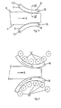
- edge-rolling elements it is possible, and sufficient for practical purposes to provide sector of angle a which is less than 360°; the length of the contact roll surface 3 being chosen in dependence on the length of slab 1 which is to be edge-rolled.
- the rolling movement of the edge-rolling elements is obtained by rotation in the direction of the arrows 11 about the centres of curvature 10.
- the edge-rolling elements do not need to be further rotated to complete 360° to roll a following slab, but can be returned to their starting positions by reverse rotation after each rolling action.
- the rolling movement can also be obtained by moving centres 10 in direction 12, parallel and opposite to the rolling direction 5.
- Figure 3 shows an embodiment where the edge-rolling elements 8 are so designed that they do not extend in the direction at right angles to the rolling surface 3 for the entire radius of curvature of the rolling surface.
- the edge-rolling elements 8 are arcuate in shape and each have a swivelling point 13 at each end. By means of a movement mechanism not shown, which is linked with swivelling points 13, the edge-rolling elements 8 are moved so as to roll the edges 4 of the slab with the two rolling surfaces 3.
- the length of the rolling surface of the edge-rolling elements can be selected such that with these edge-rolling elements a slab of maximum envisaged length can be rolled in one pass.
- the length selected can also be smaller, as shown in Figure 3, and the slab rolled in a number of passes with the edge-rolling elements.
- Figure 4 shows another embodiment of the apparatus with edge-rolling elements of a thickness of less than the radius of curvature of the rolling surface.
- the edge-rolling elements 8 are supported, guided and possibly driven by a number of back-up rolls 14, which form a track for the edge-rolling elements 8.
- the edge-rolling elements can be flexible in the rolling direction 5, with the curvature of the rolling surfaces during width rolling being dependent on the path formed by the back-up rolls 14.
- Figure 5 shows an embodiment in which the edge-rolling elements are flexible and form caterpillar or apron conveyors 15, which are closed loops.
- the edge-rolling elements 8 can have a caliber groove 16. This reduces the formation of a dog-bone in slab 1 still further.
- the bottom of the groove 16 forms the rolling surface 3 mentioned above.
- the test was carried out on a scale reduced by 10.
- the dimensions of the plasticine slab were 180 x 22.5 x 600 mm.
- the radius of curvature of the roll elements was 1000 mm.
- the width reduction was 15 mm.
Landscapes
- Engineering & Computer Science (AREA)
- Mechanical Engineering (AREA)
- Metal Rolling (AREA)
Claims (9)
Priority Applications (1)
| Application Number | Priority Date | Filing Date | Title |
|---|---|---|---|
| AT83200418T ATE14685T1 (de) | 1982-04-07 | 1983-03-25 | Geraet zur breitenverminderung einer stahlbramme durch walzen. |
Applications Claiming Priority (2)
| Application Number | Priority Date | Filing Date | Title |
|---|---|---|---|
| NL8201499A NL8201499A (nl) | 1982-04-07 | 1982-04-07 | Inrichting voor het door walsen in aanzienlijke mate reduceren van de breedte van een stalen plak. |
| NL8201499 | 1982-04-07 |
Publications (2)
| Publication Number | Publication Date |
|---|---|
| EP0091156A1 EP0091156A1 (fr) | 1983-10-12 |
| EP0091156B1 true EP0091156B1 (fr) | 1985-08-07 |
Family
ID=19839558
Family Applications (1)
| Application Number | Title | Priority Date | Filing Date |
|---|---|---|---|
| EP83200418A Expired EP0091156B1 (fr) | 1982-04-07 | 1983-03-25 | Appareil pour la réduction de la largeur d'une brame d'acier par laminage |
Country Status (5)
| Country | Link |
|---|---|
| EP (1) | EP0091156B1 (fr) |
| JP (1) | JPS58187202A (fr) |
| AT (1) | ATE14685T1 (fr) |
| DE (1) | DE3360508D1 (fr) |
| NL (1) | NL8201499A (fr) |
Families Citing this family (3)
| Publication number | Priority date | Publication date | Assignee | Title |
|---|---|---|---|---|
| JP2639594B2 (ja) * | 1989-12-23 | 1997-08-13 | 株式会社河合楽器製作所 | 電子機器 |
| JPH03200286A (ja) * | 1989-12-28 | 1991-09-02 | Kawai Musical Instr Mfg Co Ltd | 電子機器の操作装置 |
| NL9301269A (nl) * | 1993-07-20 | 1995-02-16 | Hoogovens Groep Bv | Inrichting voor het door kantwalsen uitvoeren van een grote breedtereductie op een metalen plak. |
Family Cites Families (2)
| Publication number | Priority date | Publication date | Assignee | Title |
|---|---|---|---|---|
| US3422656A (en) * | 1966-03-18 | 1969-01-21 | United States Steel Corp | Method of rolling slabs in planetary mill |
| JPS5942561B2 (ja) * | 1980-02-13 | 1984-10-16 | 新日本製鐵株式会社 | 熱間圧延方法 |
-
1982
- 1982-04-07 NL NL8201499A patent/NL8201499A/nl not_active Application Discontinuation
-
1983
- 1983-03-25 EP EP83200418A patent/EP0091156B1/fr not_active Expired
- 1983-03-25 AT AT83200418T patent/ATE14685T1/de not_active IP Right Cessation
- 1983-03-25 DE DE8383200418T patent/DE3360508D1/de not_active Expired
- 1983-04-06 JP JP58059380A patent/JPS58187202A/ja active Pending
Also Published As
| Publication number | Publication date |
|---|---|
| NL8201499A (nl) | 1983-11-01 |
| DE3360508D1 (en) | 1985-09-12 |
| ATE14685T1 (de) | 1985-08-15 |
| EP0091156A1 (fr) | 1983-10-12 |
| JPS58187202A (ja) | 1983-11-01 |
Similar Documents
| Publication | Publication Date | Title |
|---|---|---|
| SU1306468A3 (ru) | Клеть прокатного стана | |
| US3777532A (en) | Method of and apparatus for extending and reducing thickness of a metallic band | |
| US5953946A (en) | Apparatus for bend-straightening metal strip | |
| US4385512A (en) | Tandem rolling mill train for metal plate and sheet | |
| EP0091156B1 (fr) | Appareil pour la réduction de la largeur d'une brame d'acier par laminage | |
| EP0351785B1 (fr) | Méthode et appareillage pour provoquer des contraintes différentielles lors de la fabrication de bandes métalliques flexibles sans fin pour coulée continue en vue d'améliorer la performance des bandes utilisées dans les machines de coulée continue | |
| CA1257989A (fr) | Dispositif de mise en contrainte | |
| JPH0250812B2 (fr) | ||
| JPS5884614A (ja) | ロ−ラ・レベラ | |
| US4019282A (en) | Apparatus for descaling metal strips | |
| JP2882749B2 (ja) | コンクリート構造体を補強する補強部材及び該補強部材を製造する装置 | |
| US5397402A (en) | Silicon steel strip having mechanically refined magnetic domain wall spacings and method for producing the same | |
| CA1213762A (fr) | Methode et appareil pour controler la largeur et l'epaisseur d'un feuillard | |
| SU880522A1 (ru) | Непрерывный прокатный стан | |
| JPS6186006A (ja) | 厚板圧延方法及び装置 | |
| US5590559A (en) | Method and apparatus for domain refining electrical steels by local mechanical deformation with multiple scribing rolls | |
| US4483166A (en) | Device for helically coiling pressure vessel shells | |
| US4728083A (en) | Method and apparatus for scribing grain-oriented silicon steel strip | |
| JPH0760356A (ja) | H形鋼の矯正方法 | |
| JPH08276206A (ja) | 圧延機および圧延方法 | |
| JP2585608B2 (ja) | テンシヨンロ−ラレベラ | |
| US4202195A (en) | Skew rolling mill roller | |
| RU2160651C2 (ru) | Способ разливки ленты и устройство для его осуществления | |
| MX162850B (es) | Un laminador de cilindros oblicuos y un procedimiento mejorados para el laminado de barras,tubos metalicos y similares | |
| JPS60152303A (ja) | クロス圧延装置 |
Legal Events
| Date | Code | Title | Description |
|---|---|---|---|
| PUAI | Public reference made under article 153(3) epc to a published international application that has entered the european phase |
Free format text: ORIGINAL CODE: 0009012 |
|
| 17P | Request for examination filed |
Effective date: 19830325 |
|
| AK | Designated contracting states |
Designated state(s): AT BE DE FR GB IT LU SE |
|
| ITF | It: translation for a ep patent filed |
Owner name: JACOBACCI & PERANI S.P.A. |
|
| GRAA | (expected) grant |
Free format text: ORIGINAL CODE: 0009210 |
|
| AK | Designated contracting states |
Designated state(s): AT BE DE FR GB IT LU SE |
|
| REF | Corresponds to: |
Ref document number: 14685 Country of ref document: AT Date of ref document: 19850815 Kind code of ref document: T |
|
| REF | Corresponds to: |
Ref document number: 3360508 Country of ref document: DE Date of ref document: 19850912 |
|
| ET | Fr: translation filed | ||
| PLBE | No opposition filed within time limit |
Free format text: ORIGINAL CODE: 0009261 |
|
| STAA | Information on the status of an ep patent application or granted ep patent |
Free format text: STATUS: NO OPPOSITION FILED WITHIN TIME LIMIT |
|
| 26N | No opposition filed | ||
| PGFP | Annual fee paid to national office [announced via postgrant information from national office to epo] |
Ref country code: FR Payment date: 19930211 Year of fee payment: 11 Ref country code: AT Payment date: 19930211 Year of fee payment: 11 |
|
| PGFP | Annual fee paid to national office [announced via postgrant information from national office to epo] |
Ref country code: GB Payment date: 19930217 Year of fee payment: 11 |
|
| PGFP | Annual fee paid to national office [announced via postgrant information from national office to epo] |
Ref country code: SE Payment date: 19930219 Year of fee payment: 11 |
|
| PGFP | Annual fee paid to national office [announced via postgrant information from national office to epo] |
Ref country code: DE Payment date: 19930222 Year of fee payment: 11 |
|
| PGFP | Annual fee paid to national office [announced via postgrant information from national office to epo] |
Ref country code: BE Payment date: 19930223 Year of fee payment: 11 |
|
| PGFP | Annual fee paid to national office [announced via postgrant information from national office to epo] |
Ref country code: LU Payment date: 19930312 Year of fee payment: 11 |
|
| ITTA | It: last paid annual fee | ||
| EPTA | Lu: last paid annual fee | ||
| PG25 | Lapsed in a contracting state [announced via postgrant information from national office to epo] |
Ref country code: LU Free format text: LAPSE BECAUSE OF NON-PAYMENT OF DUE FEES Effective date: 19940325 Ref country code: GB Effective date: 19940325 Ref country code: AT Effective date: 19940325 |
|
| PG25 | Lapsed in a contracting state [announced via postgrant information from national office to epo] |
Ref country code: SE Free format text: LAPSE BECAUSE OF NON-PAYMENT OF DUE FEES Effective date: 19940326 |
|
| PG25 | Lapsed in a contracting state [announced via postgrant information from national office to epo] |
Ref country code: BE Effective date: 19940331 |
|
| BERE | Be: lapsed |
Owner name: HOOGOVENS GROEP B.V. Effective date: 19940331 |
|
| GBPC | Gb: european patent ceased through non-payment of renewal fee |
Effective date: 19940325 |
|
| PG25 | Lapsed in a contracting state [announced via postgrant information from national office to epo] |
Ref country code: FR Effective date: 19941130 |
|
| PG25 | Lapsed in a contracting state [announced via postgrant information from national office to epo] |
Ref country code: DE Effective date: 19941201 |
|
| REG | Reference to a national code |
Ref country code: FR Ref legal event code: ST |
|
| EUG | Se: european patent has lapsed |
Ref document number: 83200418.8 Effective date: 19941010 |