EP0090375A2 - Trommelvorrichtung mit rotierendem Magnetkopf - Google Patents
Trommelvorrichtung mit rotierendem Magnetkopf Download PDFInfo
- Publication number
- EP0090375A2 EP0090375A2 EP83102993A EP83102993A EP0090375A2 EP 0090375 A2 EP0090375 A2 EP 0090375A2 EP 83102993 A EP83102993 A EP 83102993A EP 83102993 A EP83102993 A EP 83102993A EP 0090375 A2 EP0090375 A2 EP 0090375A2
- Authority
- EP
- European Patent Office
- Prior art keywords
- drum
- rotary
- head
- magnetic head
- head drum
- Prior art date
- Legal status (The legal status is an assumption and is not a legal conclusion. Google has not performed a legal analysis and makes no representation as to the accuracy of the status listed.)
- Withdrawn
Links
Images


Classifications
-
- G—PHYSICS
- G11—INFORMATION STORAGE
- G11B—INFORMATION STORAGE BASED ON RELATIVE MOVEMENT BETWEEN RECORD CARRIER AND TRANSDUCER
- G11B5/00—Recording by magnetisation or demagnetisation of a record carrier; Reproducing by magnetic means; Record carriers therefor
- G11B5/48—Disposition or mounting of heads or head supports relative to record carriers ; arrangements of heads, e.g. for scanning the record carrier to increase the relative speed
- G11B5/52—Disposition or mounting of heads or head supports relative to record carriers ; arrangements of heads, e.g. for scanning the record carrier to increase the relative speed with simultaneous movement of head and record carrier, e.g. rotation of head
- G11B5/53—Disposition or mounting of heads on rotating support
-
- G—PHYSICS
- G11—INFORMATION STORAGE
- G11B—INFORMATION STORAGE BASED ON RELATIVE MOVEMENT BETWEEN RECORD CARRIER AND TRANSDUCER
- G11B15/00—Driving, starting or stopping record carriers of filamentary or web form; Driving both such record carriers and heads; Guiding such record carriers or containers therefor; Control thereof; Control of operating function
- G11B15/60—Guiding record carrier
- G11B15/61—Guiding record carrier on drum, e.g. drum containing rotating heads
Definitions
- This invention relates to magnetic recording and reproducing apparatus of the helical scan type, and more particularly it is concerned with a rotary magnetic head drum device for use with video tape recorders and the like of the helical scan type.
- One of the problems encountered in designing portable video tape recorders is how to obtain an overall compact size and a light weight in a portable video tape recorder.
- the head drum device plays an important role in reducing the size and weight of a video tape recorder to provide a recorder of a slim type, so that it is urgently required that the size of the head drum device be reduced and particularly the thickness thereof be decreased.
- Fig. 1 is a sectional view of the essential portions of a rotary magnetic head device, showing one example of the head drum device of the prior art.
- the rotary magnetic head device of the prior art shown in Fig. 1 will be outlined by referring to the figure.
- the head drum device comprises a stationary drum (lower drum) 2 secured to a chassis 6 by screws 7a and 7b, and a rotary drum (upper drum) 3 secured to an output shaft 4 of a motor 1 through a rotary disc 32.
- bearings 5 and 5 a magnet 8, a motor coil 9, a stator yoke 10, a stator transformer 21 and a rotor transformer 31 stacked in superposed relation in the indicated order.
- all the components should have their thicknesses reduced and the thickness of the stationary drum 2 should be reduced by decreasing the spacing between the two bearings 5 and 5, if it is desired to obtain a head drum device of the slim type by reducing its size and weight.
- the head drum device were constructed as aforesaid, it would be possible to obtain a compact size and a small thickness in a head drum device without causing deterioration of performance. To be specific, it would be possible to reduce the size and thickness to about 1/2 those of the corresponding device of the prior art.
- this invention has as its object the provision of a head drum device of a construction suitable for obtaining a compact size and a light weight in a head drum device, which is suitable for use with a magnetic recording and reproducing apparatus which tends to become more compact in size, smaller in thickness and lighter in weight.
- This invention has been developed based on the fact that in rotary magnetic head drum devices of a helical scan type, the head drum is located obliquely with respect to the tape and that they are inclined by an angle in the range between an angle substantially equal to the helical lead angle for the tape and an angle twice the helical lead angle.
- the outstanding characteristic of the invention is that one of the rotary drum and stationary drum that is located in an upper portion of the head drum device or the rotary drum, for example, is formed at an end portion (outer peripheral portion) of a surface opposite the head supporting surface thereof with a tapering surface or stepped surface commensurate with the inclination angle of the head drum or a combination of the tapering and stepped surfaces.
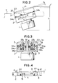
- Fig. 2 is a perspective view of a rotary magnetic head drum device of a helical scan type as mounted on a magnetic recording and reproducing apparatus (video tape recorder, for example), and
- Fig. 3 is a sectional view of the essential portions of the device.
- a head drum includes a motor 1, a stationary drum 2 formed with a tape guide section 22 and a rotary drum 3.
- the stationary drum 2 has mounted therein a stator transformer 21 and a rotor transformer 31 located in juxtaposed relation as shown in Fig. 3.
- the rotary drum 3 is secured by screws 33a and 33b to a rotary disc 32 supported by a rotary shaft 4.
- Magnetic heads 34a and 34b are mounted on head plates 35a and 35b secured to a bottom surface of the rotary drum 3 by screws 36a and 36b respectively.
- the rotary drum 3 is journaled by a bearing 5.
- the motor 1 mounts therein parts of the motor (rotating parts) including a rotor plate, a motor coil, a magnet, etc., in the same manner as previously described by referring to the head drum device, and bearings for journaling these rotating parts are also mounted in the motor 1.
- the head drum device constructed in accordance with an embodiment of the invention is shown in Figs. 2 and 3.
- the head drum including the stationary drum 2 and rotary drum 3 are located obliquely with respect to a magnetic tape T brought into contact with the drums 2 and 3 for a circumferential extent corresponding to a predetermined angle.
- the head drum is inclined by an angle 8 (VHS: 12°50') which is in the range between an angle which is substantially equal to a lead angle ⁇ ' (VHS: 5°57') of the tape edge guide section 22 on the stationary drum 2 and an angle substantially twice the lead angle or the angle 8' formed by a line l 22 extending along the tape edge guide section 22 and a line l 2 extending perpendicularly (left-wardly in Fig. 2) from a meeting point X of the line Z 22 and a line l 1 extending in a direction in which the head drum is divided into left and right half portions.
- the rotary drum 3 which is located above the stationary drum 2 has a tapering surface 371 formed on an outer peripheral portion 37 of its top surface.
- the tapering surface 371 extends obliquely upwardly from an upper end a of an outer circumferential surface D spaced apart a predetermined distance (dimension W of the rotary drum) from a head supporting surface C of the rotary drum 3, and an angle formed by a line l 371 extending along the tapering surface 371 on the outer peripheral portion 37 of the rotary drum 3 and a line l 3 extending along the top surface of the rotary drum 3 is equal to or substantially equal to the inclination angle 6 of the head drum described hereinabove.
- Fig. 5 shows another form of rotary drum according to the invention in a section view.
- the rotary drum 3 is formed with a stepped surface 372 at the outer peripheral portion 37 of its top surface which extend from the top surface to the outer circumferential surface D thereof.
- the rotary drum 3 shown in Fig. 5 is capable of achieving similar effect to the rotary drum 3 shown in Fig. 4.
- the tapering surface 371 of the rotary drum 3 shown in Fig. 4 and the stepped surface 372 thereof shown in Fig. 5 have been described as being formed by machining. However, the tapering surface 371 and stepped surface 372 may be formed integrally with the rotary drum 3 when the latter is cast in a mold, for example. What is important is not the manner in which the tapering surface 371 and stepped surface 372 are formed but that the final shape of the rotary drum 3 is as illustrated in the figures and described herein.
- Fig. 6 is a plan view of still another form of rotary drum according to the invention
- Fig. 7 is a fragmentary sectional view of the rotary drum taken along the line VII-VII in Fig. 6.
- the rotary drum 3 is formed at its outer peripheral portion 37 of its top surface with a stepped surface including a slope 373 and a planar portion 374 extending from the top surface to the outer circumferential surface D.
- the planar portion 374 has formed therein with threaded openings 42a and 42b for threadably receiving therein stop screws 41a and 41b for adjusting the height of the magnetic heads 34a and 34b, respectively, which are secured to the bottom surface of the rotary drum 3.
- the numerals 43a and 43b designate openings for adjusting the positions of the magnetic heads 34a and 34b. These openings are formed by machining performed from the top surface side of the rotary drum 3.
- the construction in which the planar portion 374 is included in the outer peripheral portion 37 of the top surface of the rotary drum 3 is advantageous for forming the openings 42a, 42b, 43a and 43b. It is required that the rotary drum 3 be embossed with its manufacturing number. This can be readily accomplished on the planar portion 374.
- a video tape recorder of the VHS system which is one type of rotary magnetic head drum device having the magnetic heads 34a and 34b attached to the rotary drum 3 and interposed between the rotary drum 3 and the stationary drum 2.
- the invention can also have application in a video tape recorder of a beta system which is the type of rotary magnetic head drum device that includes a magnetic head rotating member interposed between two drums or upper and lower stationary drums independently thereof and driven by an output shaft of a motor.
- the aforesaid tapering or stepped surface would be formed at an outer peripheral portion of a top surface of the upper stationary drum located above the lower stationary drum.
- the angle of inclination of the head drum device is substantially equal to the lead angle 8' of the tape edge guide portion.
- the tapering would have to be commensurate with this angle of inclination of the head drum device.
Applications Claiming Priority (2)
| Application Number | Priority Date | Filing Date | Title |
|---|---|---|---|
| JP44701/82U | 1982-03-31 | ||
| JP1982044701U JPS58148729U (ja) | 1982-03-31 | 1982-03-31 | 回転磁気ヘツドドラム |
Publications (2)
| Publication Number | Publication Date |
|---|---|
| EP0090375A2 true EP0090375A2 (de) | 1983-10-05 |
| EP0090375A3 EP0090375A3 (de) | 1984-09-05 |
Family
ID=12698717
Family Applications (1)
| Application Number | Title | Priority Date | Filing Date |
|---|---|---|---|
| EP83102993A Withdrawn EP0090375A3 (de) | 1982-03-31 | 1983-03-25 | Trommelvorrichtung mit rotierendem Magnetkopf |
Country Status (4)
| Country | Link |
|---|---|
| EP (1) | EP0090375A3 (de) |
| JP (1) | JPS58148729U (de) |
| KR (1) | KR880003721Y1 (de) |
| BR (1) | BR8301631A (de) |
Cited By (5)
| Publication number | Priority date | Publication date | Assignee | Title |
|---|---|---|---|---|
| EP0247442A2 (de) * | 1986-05-27 | 1987-12-02 | Hitachi, Ltd. | Trommel mit rotierenden magnetischen Köpfen für Aufzeichnung- und Wiedergabegerät |
| US4814917A (en) * | 1986-07-26 | 1989-03-21 | Sony Corporation | Rotary magnetic head device |
| US4891726A (en) * | 1986-12-30 | 1990-01-02 | Sony Corporation | Rotary magnetic head and guide drum assembly with reduce mounting height |
| US5438468A (en) * | 1991-07-18 | 1995-08-01 | Sony Corporation | Rotary head drum having reduced exterior dimensions |
| US5528438A (en) * | 1992-03-30 | 1996-06-18 | Sony Corporation | Drum assembly having a lower fixed drum and an upper rotary drum with a particularly shaped outer surface |
Citations (9)
| Publication number | Priority date | Publication date | Assignee | Title |
|---|---|---|---|---|
| US3319014A (en) * | 1961-11-29 | 1967-05-09 | Matsushita Electric Ind Co Ltd | Tape guide arrangement for use in magnetic video tape recording apparatus |
| DE1512359A1 (de) * | 1966-05-07 | 1969-06-26 | Philips Nv | Magnettongeraet |
| US3516146A (en) * | 1968-06-19 | 1970-06-23 | Westel Co | Method of assembling a helical scanning assembly |
| US3643038A (en) * | 1968-11-09 | 1972-02-15 | Sony Corp | Magnetic recording and/or reproducing system |
| US3679838A (en) * | 1970-02-19 | 1972-07-25 | Marlene D Graves | Video tape scanner with adjustably mounted transducers providing chordal adjustment |
| FR2150179A5 (de) * | 1971-08-18 | 1973-03-30 | Int Video Corp | |
| US3979772A (en) * | 1973-02-12 | 1976-09-07 | Victor Company Of Japan, Limited | Automatic tape loading type recording and/or reproducing apparatus |
| US4139873A (en) * | 1978-02-01 | 1979-02-13 | Arvin Industries, Inc. | Method and apparatus for video signal recording |
| EP0022651A1 (de) * | 1979-07-05 | 1981-01-21 | Arvin Industries, Inc. | Magnetbandaufnahmegerät mit Abtastung und Kassette |
-
1982
- 1982-03-31 JP JP1982044701U patent/JPS58148729U/ja active Pending
-
1983
- 1983-03-25 EP EP83102993A patent/EP0090375A3/de not_active Withdrawn
- 1983-03-26 KR KR2019830002702U patent/KR880003721Y1/ko not_active IP Right Cessation
- 1983-03-29 BR BR8301631A patent/BR8301631A/pt unknown
Patent Citations (9)
| Publication number | Priority date | Publication date | Assignee | Title |
|---|---|---|---|---|
| US3319014A (en) * | 1961-11-29 | 1967-05-09 | Matsushita Electric Ind Co Ltd | Tape guide arrangement for use in magnetic video tape recording apparatus |
| DE1512359A1 (de) * | 1966-05-07 | 1969-06-26 | Philips Nv | Magnettongeraet |
| US3516146A (en) * | 1968-06-19 | 1970-06-23 | Westel Co | Method of assembling a helical scanning assembly |
| US3643038A (en) * | 1968-11-09 | 1972-02-15 | Sony Corp | Magnetic recording and/or reproducing system |
| US3679838A (en) * | 1970-02-19 | 1972-07-25 | Marlene D Graves | Video tape scanner with adjustably mounted transducers providing chordal adjustment |
| FR2150179A5 (de) * | 1971-08-18 | 1973-03-30 | Int Video Corp | |
| US3979772A (en) * | 1973-02-12 | 1976-09-07 | Victor Company Of Japan, Limited | Automatic tape loading type recording and/or reproducing apparatus |
| US4139873A (en) * | 1978-02-01 | 1979-02-13 | Arvin Industries, Inc. | Method and apparatus for video signal recording |
| EP0022651A1 (de) * | 1979-07-05 | 1981-01-21 | Arvin Industries, Inc. | Magnetbandaufnahmegerät mit Abtastung und Kassette |
Cited By (6)
| Publication number | Priority date | Publication date | Assignee | Title |
|---|---|---|---|---|
| EP0247442A2 (de) * | 1986-05-27 | 1987-12-02 | Hitachi, Ltd. | Trommel mit rotierenden magnetischen Köpfen für Aufzeichnung- und Wiedergabegerät |
| EP0247442A3 (en) * | 1986-05-27 | 1989-02-22 | Hitachi, Ltd. | Rotating magnetic head device in magnetic recording and reproducing apparatus |
| US4814917A (en) * | 1986-07-26 | 1989-03-21 | Sony Corporation | Rotary magnetic head device |
| US4891726A (en) * | 1986-12-30 | 1990-01-02 | Sony Corporation | Rotary magnetic head and guide drum assembly with reduce mounting height |
| US5438468A (en) * | 1991-07-18 | 1995-08-01 | Sony Corporation | Rotary head drum having reduced exterior dimensions |
| US5528438A (en) * | 1992-03-30 | 1996-06-18 | Sony Corporation | Drum assembly having a lower fixed drum and an upper rotary drum with a particularly shaped outer surface |
Also Published As
| Publication number | Publication date |
|---|---|
| KR880003721Y1 (ko) | 1988-10-15 |
| KR840005840U (ko) | 1984-11-10 |
| EP0090375A3 (de) | 1984-09-05 |
| BR8301631A (pt) | 1983-12-13 |
| JPS58148729U (ja) | 1983-10-06 |
Similar Documents
| Publication | Publication Date | Title |
|---|---|---|
| CA1336787C (en) | In-spindle motor assembly for disk drive and method for fabricating the same | |
| US5119362A (en) | Disc player with a pickup feeding apparatus | |
| US4891726A (en) | Rotary magnetic head and guide drum assembly with reduce mounting height | |
| US5438468A (en) | Rotary head drum having reduced exterior dimensions | |
| EP0090375A2 (de) | Trommelvorrichtung mit rotierendem Magnetkopf | |
| US5363260A (en) | Magnetic disk apparatus and method for manufacturing the same | |
| US5305163A (en) | Stationary angularly aligned stationary spindle shaft | |
| JPS639288B2 (de) | ||
| US5414575A (en) | Magnetic disc drive device with hub and clamper assembly for reducing post-assembly machining | |
| JPH01105308A (ja) | 回転ヘッドドラム装置 | |
| US5369537A (en) | Disk driving device with improved disk mounting surface | |
| JPS6120724Y2 (de) | ||
| US5237471A (en) | Integrated driving system for signal-processing devices | |
| US5295033A (en) | Rotary drum device | |
| JP3033296B2 (ja) | 磁気記録再生装置 | |
| SU1583974A1 (ru) | Блок вращающихс головок дл наклонно-строчной записи-воспроизведени сигналов на магнитной ленте | |
| KR100228691B1 (ko) | 회전 헤드 드럼 장치 | |
| KR100186401B1 (ko) | 자기기록재생기용 드럼의 조립 방법 | |
| JPH02252114A (ja) | 回転ヘッドの位置調整装置 | |
| KR19980069615A (ko) | 헤드드럼조립체의 회전드럼 | |
| JPH0115929B2 (de) | ||
| KR850003250Y1 (ko) | 컴팩트 디스크(혹은 디지탈 오디오 디스크)플레이어 옵티컬 픽업 어셈블리(optical pick-up assembly)의 선형 이송장치 | |
| JP2545167B2 (ja) | ラップ加工装置 | |
| JPH05174305A (ja) | 回転磁気ヘッド装置 | |
| JPH0713120Y2 (ja) | 磁気ディスク装置 |
Legal Events
| Date | Code | Title | Description |
|---|---|---|---|
| PUAI | Public reference made under article 153(3) epc to a published international application that has entered the european phase |
Free format text: ORIGINAL CODE: 0009012 |
|
| AK | Designated contracting states |
Designated state(s): AT DE FR GB IT |
|
| PUAL | Search report despatched |
Free format text: ORIGINAL CODE: 0009013 |
|
| AK | Designated contracting states |
Designated state(s): AT DE FR GB IT |
|
| 17P | Request for examination filed |
Effective date: 19850211 |
|
| 17Q | First examination report despatched |
Effective date: 19860612 |
|
| STAA | Information on the status of an ep patent application or granted ep patent |
Free format text: STATUS: THE APPLICATION IS DEEMED TO BE WITHDRAWN |
|
| 18D | Application deemed to be withdrawn |
Effective date: 19870324 |
|
| RIN1 | Information on inventor provided before grant (corrected) |
Inventor name: YOSHIDA, NAOTO Inventor name: OKADA, SHINJI Inventor name: MORIYAMA, YASUJI Inventor name: KOCHI, MASANORI |